

oSIST prEN 17082:2026
(Main)Domestic and non-domestic gas-fired forced convection air heaters for space heating not exceeding a net heat input of 300 kW
General Information
- Abstract
This document specifies the requirements and test methods for the safety and efficiency of gas fired air heaters with or without a fan to assist the transportation of combustion air and/or flue gases.
This document also applies to warm air heaters having forced draught burners.
This document applies to Type A2, A3 appliances, with an input not exceeding 300 kW (net CV basis), intended for non-domestic use.
This document also applies to Type B11, B11AS, B11BS, B12, B12AS, B12BS, B13, B13AS, B13BS, B14, B14AS, B14BS, B22, B23, B41, B41AS, B41BS, B42, B42AS, B42BS, B43, B43AS, B43BS, B44, B44AS, B44BS, B52, B53, C11, C12, C13, C21, C31, C32, C33, C41, C52, C53, C62 and C63 appliances with an input not exceeding 300 kW (net CV basis), intended for domestic and non-domestic use.
The heated air can be delivered by means of ducting.
This document applies only to appliances using the gaseous fuels of the second and third families as defined in EN 437. For second family gases, this includes H₂NG blends containing up to 20 % hydrogen by volume, where the appliance is marked with the appropriate extended category (e.g. I2H, I2E, I2E(Y20)). This document does not apply to appliances intended to burn gases containing carbon monoxide or other toxic components.
This document does not apply to:
a) dual purpose air conditioning appliances (heating and cooling);
b) appliances where the air is heated by an intermediate fluid;
c) portable or transportable forced convection appliances;
d) appliances fitted with manual or automatic means of adjusting the combustion products evacuation by means of flue dampers;
e) appliances having multiple heating units with a single draught diverter;
f) appliances fitted with more than one flue outlet;
g) appliances fitted with gas boosters;
h) C21 and C41 appliances for 3rd family gases.
NOTE 1 Appliance Types (A, B and C) are classified in accordance with EN 1749.
NOTE 2 For C41 appliances, see all requirements and test methods that are valid for C21 appliances, unless otherwise stated.
- Status
- Not Published
- Public Enquiry End Date
- 01-Dec-2026
- Technical Committee
- PLN - Gas appliances for domestic use
- Current Stage
- 4020 - Public enquire (PE) (Adopted Project)
- Start Date
- 30-Sep-2026
- Due Date
- 17-Feb-2027

Relations
- Effective Date
- 01-Nov-2026
Frequently Asked Questions
oSIST prEN 17082:2026 is a draft published by the Slovenian Institute for Standardization (SIST). Its full title is "Domestic and non-domestic gas-fired forced convection air heaters for space heating not exceeding a net heat input of 300 kW". This standard covers: This document specifies the requirements and test methods for the safety and efficiency of gas fired air heaters with or without a fan to assist the transportation of combustion air and/or flue gases. This document also applies to warm air heaters having forced draught burners. This document applies to Type A2, A3 appliances, with an input not exceeding 300 kW (net CV basis), intended for non-domestic use. This document also applies to Type B11, B11AS, B11BS, B12, B12AS, B12BS, B13, B13AS, B13BS, B14, B14AS, B14BS, B22, B23, B41, B41AS, B41BS, B42, B42AS, B42BS, B43, B43AS, B43BS, B44, B44AS, B44BS, B52, B53, C11, C12, C13, C21, C31, C32, C33, C41, C52, C53, C62 and C63 appliances with an input not exceeding 300 kW (net CV basis), intended for domestic and non-domestic use. The heated air can be delivered by means of ducting. This document applies only to appliances using the gaseous fuels of the second and third families as defined in EN 437. For second family gases, this includes H₂NG blends containing up to 20 % hydrogen by volume, where the appliance is marked with the appropriate extended category (e.g. I2H, I2E, I2E(Y20)). This document does not apply to appliances intended to burn gases containing carbon monoxide or other toxic components. This document does not apply to: a) dual purpose air conditioning appliances (heating and cooling); b) appliances where the air is heated by an intermediate fluid; c) portable or transportable forced convection appliances; d) appliances fitted with manual or automatic means of adjusting the combustion products evacuation by means of flue dampers; e) appliances having multiple heating units with a single draught diverter; f) appliances fitted with more than one flue outlet; g) appliances fitted with gas boosters; h) C21 and C41 appliances for 3rd family gases. NOTE 1 Appliance Types (A, B and C) are classified in accordance with EN 1749. NOTE 2 For C41 appliances, see all requirements and test methods that are valid for C21 appliances, unless otherwise stated.
This document specifies the requirements and test methods for the safety and efficiency of gas fired air heaters with or without a fan to assist the transportation of combustion air and/or flue gases. This document also applies to warm air heaters having forced draught burners. This document applies to Type A2, A3 appliances, with an input not exceeding 300 kW (net CV basis), intended for non-domestic use. This document also applies to Type B11, B11AS, B11BS, B12, B12AS, B12BS, B13, B13AS, B13BS, B14, B14AS, B14BS, B22, B23, B41, B41AS, B41BS, B42, B42AS, B42BS, B43, B43AS, B43BS, B44, B44AS, B44BS, B52, B53, C11, C12, C13, C21, C31, C32, C33, C41, C52, C53, C62 and C63 appliances with an input not exceeding 300 kW (net CV basis), intended for domestic and non-domestic use. The heated air can be delivered by means of ducting. This document applies only to appliances using the gaseous fuels of the second and third families as defined in EN 437. For second family gases, this includes H₂NG blends containing up to 20 % hydrogen by volume, where the appliance is marked with the appropriate extended category (e.g. I2H, I2E, I2E(Y20)). This document does not apply to appliances intended to burn gases containing carbon monoxide or other toxic components. This document does not apply to: a) dual purpose air conditioning appliances (heating and cooling); b) appliances where the air is heated by an intermediate fluid; c) portable or transportable forced convection appliances; d) appliances fitted with manual or automatic means of adjusting the combustion products evacuation by means of flue dampers; e) appliances having multiple heating units with a single draught diverter; f) appliances fitted with more than one flue outlet; g) appliances fitted with gas boosters; h) C21 and C41 appliances for 3rd family gases. NOTE 1 Appliance Types (A, B and C) are classified in accordance with EN 1749. NOTE 2 For C41 appliances, see all requirements and test methods that are valid for C21 appliances, unless otherwise stated.
oSIST prEN 17082:2026 is classified under the following ICS (International Classification for Standards) categories: 97.100.20 - Gas heaters. The ICS classification helps identify the subject area and facilitates finding related standards.
oSIST prEN 17082:2026 has the following relationships with other standards: It is inter standard links to SIST EN 17082:2020. Understanding these relationships helps ensure you are using the most current and applicable version of the standard.
oSIST prEN 17082:2026 is associated with the following European legislation: EU Directives/Regulations: 2016/2281, 2016/426; Standardization Mandates: M/560, M/595. When a standard is cited in the Official Journal of the European Union, products manufactured in conformity with it benefit from a presumption of conformity with the essential requirements of the corresponding EU directive or regulation.
oSIST prEN 17082:2026 is available in PDF format for immediate download after purchase. The document can be added to your cart and obtained through the secure checkout process. Digital delivery ensures instant access to the complete standard document.
Standards Content (Sample)
SLOVENSKI STANDARD
01-november-2026
Plinski grelniki zraka s prisilno konvekcijo za gretje stanovanjskih in
nestanovanjskih prostorov z nazivno močjo do vključno 300 kW
Domestic and non-domestic gas-fired forced convection air heaters for space heating not
exceeding a net heat input of 300 kW
Häusliche und nicht-häusliche gasbefeuerte Warmlufterzeuger mit erzwungener
Konvektion zur Raumbeheizung, deren Nennwärmebelastung 300 kW nicht übersteigt
Générateurs d'air chaud à convection forcée utilisant les combustibles gazeux pour le
chauffage de locaux à usage domestique et non domestique, de débit calorifique
inférieur ou égal à 300 kW, sur pouvoir calorifique inférieur (PCI)
Ta slovenski standard je istoveten z: prEN 17082
ICS:
97.100.20 Plinski grelniki Gas heaters
2003-01.Slovenski inštitut za standardizacijo. Razmnoževanje celote ali delov tega standarda ni dovoljeno.
DRAFT
EUROPEAN STANDARD
NORME EUROPÉENNE
EUROPÄISCHE NORM
October 2026
ICS 97.100.20 Will supersede EN 17082:2019
English Version
Domestic and non-domestic gas-fired forced convection air
heaters for space heating not exceeding a net heat input of
300 kW
Générateurs d'air chaud à convection forcée utilisant Häusliche und nicht-häusliche gasbefeuerte
les combustibles gazeux pour le chauffage de locaux à Warmlufterzeuger mit erzwungener Konvektion zur
usage domestique et non domestique, de débit Raumbeheizung, deren Nennwärmebelastung 300 kW
calorifique inférieur ou égal à 300 kW, sur pouvoir nicht übersteigt
calorifique inférieur (PCI)
This draft European Standard is submitted to CEN members for enquiry. It has been drawn up by the Technical Committee
CEN/TC 180.
If this draft becomes a European Standard, CEN members are bound to comply with the CEN/CENELEC Internal Regulations
which stipulate the conditions for giving this European Standard the status of a national standard without any alteration.
This draft European Standard was established by CEN in three official versions (English, French, German). A version in any other
language made by translation under the responsibility of a CEN member into its own language and notified to the CEN-CENELEC
Management Centre has the same status as the official versions.
CEN members are the national standards bodies of Austria, Belgium, Bulgaria, Croatia, Cyprus, Czech Republic, Denmark, Estonia,
Finland, France, Germany, Greece, Hungary, Iceland, Ireland, Italy, Latvia, Lithuania, Luxembourg, Malta, Netherlands, Norway,
Poland, Portugal, Republic of North Macedonia, Romania, Serbia, Slovakia, Slovenia, Spain, Sweden, Switzerland, Türkiye and
United Kingdom.
Recipients of this draft are invited to submit, with their comments, notification of any relevant patent rights of which they are
aware and to provide supporting documentation.
Warning : This document is not a European Standard. It is distributed for review and comments. It is subject to change without
notice and shall not be referred to as a European Standard.
EUROPEAN COMMITTEE FOR STANDARDIZATION
COMITÉ EUROPÉEN DE NORMALISATION
EUROPÄISCHES KOMITEE FÜR NORMUNG
CEN-CENELEC Management Centre: Rue de la Science 23, B-1040 Brussels
© 2026 CEN All rights of exploitation in any form and by any means reserved Ref. No. prEN 17082:2026 E
worldwide for CEN national Members.
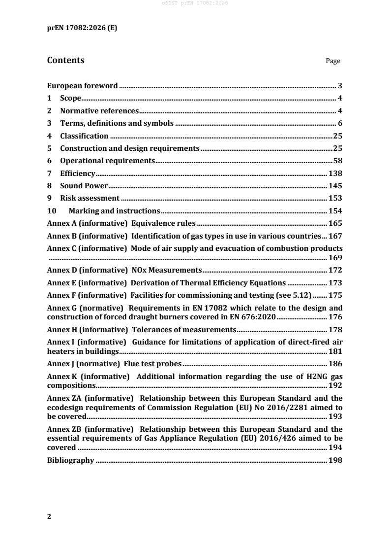
Contents Page
European foreword . 3
1 Scope. 4
2 Normative references . 4
3 Terms, definitions and symbols . 6
4 Classification . 25
5 Construction and design requirements . 25
6 Operational requirements . 58
7 Efficiency . 138
8 Sound Power . 145
9 Risk assessment . 153
10 Marking and instructions . 154
Annex A (informative) Equivalence rules . 165
Annex B (informative) Identification of gas types in use in various countries . 167
Annex C (informative) Mode of air supply and evacuation of combustion products
.......................................................................................................................................................... 169
Annex D (informative) NOx Measurements . 172
Annex E (informative) Derivation of Thermal Efficiency Equations . 173
Annex F (informative) Facilities for commissioning and testing (see 5.12) . 175
Annex G (normative) Requirements in EN 17082 which relate to the design and
construction of forced draught burners covered in EN 676:2020 . 176
Annex H (informative) Tolerances of measurements . 178
Annex I (informative) Guidance for limitations of application of direct-fired air
heaters in buildings . 181
Annex J (normative) Flue test probes . 186
Annex K (informative) Additional information regarding the use of H2NG gas
compositions . 192
Annex ZA (informative) Relationship between this European Standard and the
ecodesign requirements of Commission Regulation (EU) No 2016/2281 aimed to
be covered . 193
Annex ZB (informative) Relationship between this European Standard and the
essential requirements of Gas Appliance Regulation (EU) 2016/426 aimed to be
covered . 194
Bibliography . 198
European foreword
This document (prEN 17082:2026) has been prepared by Technical Committee CEN/TC 180
“Decentralized gas heating”, the secretariat of which is held by AFNOR
This document is currently submitted to the CEN Enquiry.
This document will supersede EN 17082:2019.
This document covers the safety and energy efficiency requirements of domestic and non-
domestic warm air heaters. Additional technical requirements have been made compared to the
superseded document to take account of the following:
— specific requirements on risk analysis due to differences in the Essential Requirements for
the Gas Appliance Regulation compared to those of the Gas Appliance Directive;
— additional requirements on appliance efficiency, including the need to calculate the seasonal
efficiency related to the requirements of the Eco-Design Regulation.
This document has been prepared under a standardization request addressed to CEN by the
European Commission. The Standing Committee of the EFTA States subsequently approves these
requests for its Member States.
For the relationship with EU Legislation, see informative Annexes ZA and ZB, which are integral
parts of this document.
1 Scope
This document specifies the requirements and test methods for the safety and efficiency of gas
fired air heaters with or without a fan to assist the transportation of combustion air and/or flue
gases.
This document also applies to warm air heaters having forced draught burners.
, A appliances, with an input not exceeding 300 kW (net CV
This document applies to Type A2 3
basis), intended for non-domestic use.
This document also applies to Type B , B , B , B , B , B , B , B , B , B , B , B ,
11 11AS 11BS 12 12AS 12BS 13 13AS 13BS 14 14AS 14BS
B , B , B , B , B , B , B , B , B , B , B , B , B , B , B , B , C , C , C , C ,
22 23 41 41AS 41BS 42 42AS 42BS 43 43AS 43BS 44 44AS 44BS 52 53 11 12 13 21
C , C , C , C , C , C , C and C appliances with an input not exceeding 300 kW (net CV basis),
31 32 33 41 52 53 62 63
intended for domestic and non-domestic use.
The heated air can be delivered by means of ducting.
This document applies only to appliances using the gaseous fuels of the second and third families
as defined in EN 437. For second family gases, this includes H NG blends containing up to 20 %
hydrogen by volume, where the appliance is marked with the appropriate extended category (e.g.
I2H, I2E, I2E(Y20)). This document does not apply to appliances intended to burn gases
containing carbon monoxide or other toxic components.
This document does not apply to:
a) dual purpose air conditioning appliances (heating and cooling);
b) appliances where the air is heated by an intermediate fluid;
c) portable or transportable forced convection appliances;
d) appliances fitted with manual or automatic means of adjusting the combustion products
evacuation by means of flue dampers;
e) appliances having multiple heating units with a single draught diverter;
f) appliances fitted with more than one flue outlet;
g) appliances fitted with gas boosters;
h) C and C appliances for 3rd family gases.
21 41
NOTE 1 Appliance Types (A, B and C) are classified in accordance with EN 1749.
NOTE 2 For C41 appliances, see all requirements and test methods that are valid for C21 appliances,
unless otherwise stated.
2 Normative references
The following documents are referred to in the text in such a way that some or all of their content
constitutes requirements of this document. For dated references, only the edition cited applies.
For undated references, the latest edition of the referenced document (including any
amendments) applies.
EN 88-1:2022+A1:2023, Safety and control devices for gas burners and gas burning appliances -
Part 1: Pressure regulators for inlet pressures up to and including 50 kPa
EN 125:2022+A1:2024, Flame supervision devices for gas burning appliances - Thermoelectric
flame supervision devices
EN 126:2025, Safety and control devices for burners and appliances burning gaseous fuels -
Multifunctional controls
EN 161:2022+A1:2025, Automatic shut-off valves for gas burners and gas appliances
EN 257:2022+A1:2023, Mechanical thermostats for gas-burning appliances
EN 298:2022, Automatic burner control systems for burners and appliances burning gaseous or
liquid fuels
EN 437:2021, Test gases - Test pressures - Appliance categories
EN 549:2019+A2:2024, Rubber materials for seals and diaphragms for gas appliances and gas
equipment
EN 676:2020, Forced draught burners for gaseous fuels
EN 1859:2009+A1:2013, Chimneys - Metal chimneys - Test methods
EN 10226-2:2005, Pipe threads where pressure tight joints are made on the threads - Part 2: Taper
external threads and taper internal threads - Dimensions, tolerances and designation
EN 12067-2:2022, Safety and control devices for burners and appliances burning gaseous or liquid
fuels - Control functions in electronic systems - Part 2: Fuel/air ratio control/supervision of the
electronic type
EN 50090-1:2011, Home and Building Electronic Systems (HBES) - Part 1: Standardization
structure
EN ISO 228-1:2003, Pipe threads where pressure-tight joints are not made on the threads - Part 1:
Dimensions, tolerances and designation (ISO 228-1:2000)
EN ISO 1182:2020, Reaction to fire tests for products - Non-combustibility test (ISO 1182:2020)
EN ISO 3166-1:2020, Codes for the representation of names of countries and their subdivisions -
Part 1: Country code (ISO 3166-1:2020)
EN ISO 3740:2019, Acoustics - Determination of sound power levels of noise sources - Guidelines for
the use of basic standards (ISO 3740:2019)
EN ISO 3741:2010, Acoustics - Determination of sound power levels and sound energy levels of noise
sources using sound pressure - Precision methods for reverberation test rooms (ISO 3741:2010)
EN ISO 3743-1:2010, Acoustics - Determination of sound power levels and sound energy levels of
noise sources using sound pressure - Engineering methods for small movable sources in reverberant
fields - Part 1: Comparison method for a hard-walled test room (ISO 3743-1:2010)
As impacted by EN 676:2020/AC:2022.
EN ISO 3743-2:2019, Acoustics - Determination of sound power levels of noise sources using sound
pressure - Engineering methods for small, movable sources in reverberant fields - Part 2: Methods
for special reverberation test rooms (ISO 3743-2:2018)
EN ISO 3744:2026, Acoustics - Determination of sound power levels of noise sources using sound
pressure - Engineering methods for an essentially free field over a reflecting plane (ISO 3744:2025,
including corrected version 2026-01)
EN IEC 60335-1:2023, Household and similar electrical appliances - Safety - Part 1: General
requirements (IEC 60335-1:2020)
EN IEC 60335-2-102:2024, Household and similar electrical appliances - Safety - Part 2-102:
Particular requirements for gas, oil and solid-fuel burning appliances having electrical connections
(IEC 60335-2-102:2017)
EN 60529:1991, Degrees of protection provided by enclosures (IP Code) (IEC 60529:1989)
EN 60584-1:2013, Thermocouples - Part 1: EMF specifications and tolerances (IEC 60584-1:2013)
EN IEC 60730-1:2024, Automatic electrical controls - Part 1: General requirements (IEC 60730-
1:2022)
EN IEC 60730-2-9:2026, Automatic electrical controls - Part 2-9: Particular requirements for
temperature sensing controls (IEC 60730-2-9:2026)
EN IEC 61558-2-6:2025, Safety of transformers, reactors, power supply units and combinations
thereof - Part 2-6: Particular requirements and tests for safety isolating transformers and power
supply units incorporating safety isolating transformers for general applications (IEC 61558-2-
6:2021)
EN IEC 61558-2-16:2025, Safety of transformers, reactors, power supply units and combinations
thereof - Part 2-16: Particular requirements and tests for switch mode power supply units and
transformers for switch mode power supply units for general applications (IEC 61558-2-16:2021)
ISO 7005-1:2011, Pipe flanges - Part 1: Steel flanges for industrial and general service piping
systems
ISO 7005-2:1988, Metallic flanges - Part 2: Cast iron flanges
ISO 7005-3:1988, Metallic flanges - Part 3: Copper alloy and composite flanges
3 Terms, definitions and symbols
3.1 Terms and definitions
For the purposes of this document, the following terms and definitions apply.
As impacted by EN IEC 60335-1:2023/A11:2023.
As impacted by EN IEC 60335-2-102:2024/A11:2024.
As impacted by EN 60529:1991/corrigendum May 1993, EN 60529:1991/A1:2000; EN 60529:1991/A2:2013;
EN 60529:1991/AC:2016-12, and EN 60529:1991/A2:2013/AC:2019-02.
As impacted by EN IEC 60730-1:2024/A11:2024.
ISO and IEC maintain terminological databases for use in standardization at the following
addresses:
— IEC Electropedia: available at https://www.electropedia.org/
— ISO Online browsing platform: available at https://www.iso.org/obp
3.1.1 Appliance and its constituent components
3.1.1.1
air heater
appliance designed for the heating by means of warm air and possibly ventilation of a building
3.1.1.2
forced convection air heater
appliance designed to provide space heating from a central source by distributing heated air, by
means of an air moving device, either through ducting or directly into the heated space
3.1.1.3
direct fired forced convection air heater
forced convection air heater in which the products of combustion mix with the heated air being
supplied to the space
3.1.1.4
high temperature direct fired forced convection air heater
direct fired forced convection air heater designed to operate with an air temperature rise through
the appliance greater than 60 K
3.1.1.5
low temperature direct fired forced convection air heater
direct fired forced convection air heater designed to operate with a maximum air temperature
rise through the appliance of 60 K or less
3.1.1.6
appliance with facility for downstream re circulation of air
appliance in which a proportion of the heated air can be returned to the appliance at a point
downstream of the burner and re distributed
3.1.1.7
appliance with facility for upstream re circulation of air
appliance in which a proportion of the heated air can be returned to the appliance at a point
upstream of the burner and re distributed
3.1.1.8
profile plates
fixed or adjustable plates fitted for the purpose of setting the air flow velocity across the burner
3.1.1.9
gas inlet connection
part of the appliance intended to be connected to the gas supply
3.1.1.10
mechanical joint
mechanical means of ensuring the soundness of an assembly of several (generally metallic) parts
without the use of liquids (e.g. pastes and tapes)
EXAMPLES Metal to metal joints; conical joints; toroidal sealing rings (“O” rings); flat joints.
3.1.1.11
gas circuit
part of the appliance/burner that conveys or contains the gas between the appliance/burner gas
inlet connection and the burner(s)
3.1.1.12
restrictor
device with an orifice, which is placed in the gas circuit so as to create a pressure drop and thus
reduce the gas pressure at the burner to a predetermined value for a given supply pressure and
rate
3.1.1.13
gas rate adjuster
component allowing the gas rate of the burner to be set to a predetermined value according to
the supply conditions
Note 1 to entry: Adjustment may be progressive (screw adjuster) or in discrete steps (by changing
restrictors).
Note 2 to entry: The adjusting screw of an adjustable regulator is regarded as a gas rate adjuster.
Note 3 to entry: The action of adjusting this device is called “adjusting the gas rate”.
Note 4 to entry: A factory sealed gas rate adjuster is considered to be non-existent.
3.1.1.14
setting an adjuster
immobilizing of an adjuster after the gas rate has been adjusted
Note 1 to entry: By means such as a screw.
3.1.1.15
sealing an adjuster
arrangement made to make evident any attempt to change an adjustment, or the putting of an
adjuster or a control, out of service
3.1.1.16
injector
component that admits the gas into a burner
3.1.1.17
main burner
burner that is intended to assure the thermal function of the appliance
3.1.1.18
forced draught burner
burner in which the combustion air is introduced by means of a fan
3.1.1.19
ignition device
means used to ignite the gas at the ignition burner or at the main burner
Note 1 to entry: This device can operate intermittently or permanently.
EXAMPLE Flame, electrical ignition device.
3.1.1.20
ignition burner
burner whose flame is intended to ignite another burner
3.1.1.21
permanent ignition burner
ignition burner that operates continuously throughout the whole period that the appliance is in
use
3.1.1.22
intermittent ignition burner
ignition burner that is ignited before and extinguished at the same time as the main burner
3.1.1.23
alternating ignition burner
ignition burner that is extinguished as soon as ignition of the main burner is effected, and that re-
ignites at the main burner flame just before the latter goes out
3.1.1.24
interrupted ignition burner
ignition burner that operates only during the ignition sequence
3.1.1.25
aeration adjuster
device enabling the combustion air flow rate to be set at the desired value according to the supply
conditions
Note 1 to entry: The action of adjusting this device is called “adjusting the aeration”.
3.1.1.26
combustion circuit
circuit from the air inlet to the combustion products outlet of the appliance
Note 1 to entry: This will include the combustion chamber and heat exchanger and depending on the type
includes the air supply duct, the combustion products evacuation duct, the fitting piece, the connection to
the terminal, the inlet terminal, the outlet terminal.
3.1.1.27
air supply duct
means of transporting combustion air to the burner
3.1.1.28
combustion chamber
enclosure inside which combustion of the air-gas mixture takes place
3.1.1.29
flue outlet
part of a Type B appliance that connects with a flue to evacuate the products of combustion
3.1.1.30
draught diverter
device placed in the combustion circuit to reduce the influence of flue-pull and that of down-
draught on the burner performance and combustion
3.1.1.31
flue damper
manual or automatic device placed in the POCED intended to restrict or fully close off the
passageways for the evacuation of products of combustion when the appliance is not in use
3.1.1.32
flue terminal
device fitted at the end of the duct system which enables the discharge of flue gases and may, at
the same time, allow entry of combustion air
3.1.1.33
C flue terminal
terminal which is specially approved for Type C appliances
3.1.1.34
terminal guard
device that protects the terminal from mechanical damage from outside influences
3.1.1.35
flue adaptor box
device that adapts the appliance for connection to different duct systems
EXAMPLE An adaptor box to change from concentric to separate ducts.
3.1.1.36
POCED
combustion products evacuation duct intended for use only with a specific appliance or system
Note 1 to entry: The duct may be supplied with the appliance or identified in the installation instructions
as the matching component to be used with that appliance or system
3.1.1.37
fully premixed burner
pre-aerated burner system in which gas is mixed in a pre-determined and adjustable ratio with
all of the air necessary for combustion
3.1.1.38
gas/air ratio control
device that automatically adapts the combustion air rate to the gas rate and vice versa
3.1.2 Adjustment, control and safety devices
3.1.2.1
range rating device
component on the appliance intended to be used by the installer to adjust the heat input of the
appliance, within a range of heat inputs stated in the installation instructions, to suit the actual
heat requirements of the installation
Note 1 to entry: This adjustment may be progressive (e.g. by use of a screw adjuster) or in discrete steps
(e.g. by changing restrictors).
3.1.2.2
automatic burner control system
system comprising a programming unit and all the elements of a flame detector device
Note 1 to entry: The various functions of an automatic burner control system may be in one or more
housings.
[SOURCE: EN 298:2022]
3.1.2.3
programming unit
unit that executes a program in response to signals from control and safety devices, provides
control commands, manages the start-up sequence, supervises burner operation, and initiates
controlled or safety shut-down including lock-out, if necessary
Note 1 to entry: The programming unit follows a predetermined sequence of actions and always operates
in conjunction with a flame detector device.
[SOURCE: EN 298:2022, Modified]
3.1.2.4
flame detector device
device that produces an output signal corresponding to the detection of a flame by a flame sensor
Note 1 to entry: A flame detector device can consist of a flame sensor, an amplifier and a relay for signal
transmission. These parts, with the possible exception of the actual flame sensor, may be assembled in a
single housing for use in conjunction with a programming unit.
[SOURCE: EN 298:2022]
3.1.2.5
flame signal
signal given by the flame detector device when the flame sensor senses a flame
[SOURCE: EN 298:2022, modified]
3.1.2.6
pressure regulator
device which maintains the outlet pressure constant independent of the variations in inlet
pressure and/or flow rate within defined limits
3.1.2.7
adjustable pressure regulator
regulator provided with means for changing the outlet pressure setting
3.1.2.8
volume regulator
device which maintains the gas rate constant within a given tolerance, independent of the
upstream pressure
3.1.2.9
flame supervision device
device that, in response to a signal from the flame detector, keeps the gas supply open and shuts
it off in the absence of the supervised flame
3.1.2.10
automatic shut-off valve
valve designed to open when energized and to close automatically when de energized
3.1.2.11
control thermostat
room temperature control thermostat
device controlling the operation of the appliance (by on/off, high/low or modulating control) and
enabling the room temperature to be kept automatically, within a given tolerance, at a
predetermined value
3.1.2.12
overheat cut-off device
temperature sensing control device, integral to the appliance, intended to monitor the
performance of the appliance and to cause safety shutdown followed by a non-volatile lockout if
abnormally high air temperatures are detected, and which has no provision for setting by the user
3.1.2.13
temperature limit device
temperature sensing control device, integral to the appliance, used in conjunction with an
overheat cut-off device to cause shut-down of the main burner in the event of an overheat
condition (e.g. resulting from reduced air flow)
Note 1 to entry: The temperature limit device can be of the automatic or the manual reset type.
3.1.2.14
fan control
fan delay control
control that starts and/or stops the air delivery fan when the temperature of the delivered air
reaches certain predetermined values
3.1.2.15
temperature sensing element
temperature sensor
component that detects the temperature of the environment to be supervised or controlled
Note 1 to entry: A Type 2K sensor has the definition given in EN IEC 60730-1:2024.
3.1.2.16
combustion products discharge safety system
system that automatically shuts off the gas supply to the main burner, and perhaps to the ignition
burner, when spillage of combustion products from the draught diverter is detected
3.1.2.17
atmosphere sensing device
device intended to shut off the gas supply to the burner before vitiation of the atmosphere of the
room in which it is installed, by combustion products from the heating appliance, reaches a
predetermined threshold value
3.1.2.18
modulating control
automatic control by which the heat input of the appliance can be varied in a continuous manner
between the nominal heat input and a minimum heat input value
3.1.2.19
high/low control
automatic control which permits an appliance to operate either at the nominal heat input or at a
fixed predetermined reduced heat input
3.1.2.20
vent valve
normally open automatic valve fitted between two automatic shut off valves and intended to vent
any small leakages of gas
3.1.2.21
air flow proving device
device which monitors and proves the existence of an adequate flow of air for combustion and,
where appropriate, for dilution
3.1.2.22
closed position indicator switch
switch fitted to an automatic shut-off valve which indicates when the closure member is in the
closed position
3.1.2.23
proof of closure switch
switch fitted to an automatic shut-off valve with mechanical overtravel which indicates when the
closure member is in the closed position
3.1.2.24
valve proving system
system to check the effective closure of the start gas or main gas safety shut off valves, and which
is capable of detecting small gas leakage rates (e.g. by means of a pressure or vacuum proving
system)
3.1.3 Operation of the appliance
3.1.3.1
volume flow rate
volume of gas consumed by the appliance in unit time during continuous operation
Note 1 to entry: The volume flow rate is expressed in cubic metres per hour (m /h), litres per minute
3 3
(l/min), cubic decimetres per hour (dm /h) or cubic decimetres per second (dm /s).
[SOURCE: EN 437:2021]
3.1.3.2
mass flow rate
mass of gas consumed by the appliance in unit time during continuous operation
Note 1 to entry: The mass flow rate is expressed in kilograms per hour (kg/h) or grams per hour (g/h).
[SOURCE: EN 437:2021]
3.1.3.3
heat input
quantity of energy used in unit time corresponding to the volumetric or mass flow rates, the
calorific value used being the net or gross calorific value
Note 1 to entry: The heat input is expressed in kilowatts (kW).
[SOURCE: EN 437:2021]
3.1.3.4
nominal heat input
value of the heat input declared by the installation instructions
Note 1 to entry: The nominal heat input is expressed in kilowatts (kW).
[SOURCE: EN 437:2021, modified]
3.1.3.5
flame stability
characteristic of flames which remain on the flame ports or in the flame reception zone intended
by the construction
3.1.3.6
flame lift
total or partial lifting of the base of the flame away from the burner port or the flame reception
zone provided by the design
Note 1 to entry: Flame lift may cause the flame to blow out (i.e. extinction of the air-gas mixture).
3.1.3.7
light-back
entry of a flame into the body of the burner
3.1.3.8
light-back at the injector
ignition of the gas at the injector, either as a result of light-back into the burner or by the
propagation of a flame outside the burner
3.1.3.9
sooting
phenomenon appearing during incomplete combustion and characterized by deposits of soot on
the surfaces or parts in contact with the combustion products or with the flame
3.1.3.10
yellow tipping
yellowing of the tip of the blue cone of an aerated flame
3.1.3.11
first safety time
interval between the ignition burner gas valve, the start gas valve or main gas valve, as applicable,
being energized and the ignition burner gas valve, start gas valve or main gas valve, as applicable,
being de-energized if the flame detector signals the absence of a flame at the end of this interval
Note 1 to entry: Where there is no second safety time, this is called the safety time.
3.1.3.12
second safety time
interval between the main gas valve being energized and the main gas valve being de-energized
if the flame detector signals the absence of a flame, this being where there is a first safety time to
either an ignition burner or start gas flame only
3.1.3.13
waiting time
time between safety shut down any (re)start attempt
3.1.3.14
start gas
gas that is supplied at the start gas rate to establish the start gas flame
3.1.3.15
start gas rate
restricted gas flow rate admitted either to a separate ignition burner or to the main burner during
the first safety time
3.1.3.16
start gas flame
flame established at the start gas rate either at the main burner or at a separate ignition burner
3.1.3.17
running condition of the system
running condition in which the burner is in normal operation under the supervision of the
programming unit and its flame detector device
3.1.3.18
controlled shut-down
process by which the power to the gas shut off valve(s) is removed immediately, e.g. as a result of
the action of a controlling function
[SOURCE: EN 298:2022]
3.1.3.19
safety shut-down
automatic closure of the fuel-supply system, initiated immediately following the response of a
protection device or a fault in the automatic burner control system, which puts the burner out of
operation
Note 1 to entry: The resulting state of the system is defined by de-energised terminals for the automatic
gas shut-off valves and the ignition device.
[SOURCE: EN 298:2022, modified]
3.1.3.20
non-volatile lock-out
lockout condition which can only be reset by manual means and not automatically
[SOURCE: EN 298:2022]
3.1.3.21
volatile lock-out
safety shut down condition of the system, such that a restart can only be accomplished by either
the manual reset of the system or an interruption of the electrical supply and its subsequent
restoration
[SOURCE: EN 298:2022, modified]
3.1.3.22
spark restoration
process by which, after disappearance of the flame signal, the ignition device is energized again
without the gas supply having been totally interrupted
Note 1 to entry: This process ends with the restoration of the running condition or, if there is no flame
signal at the end of the safety time, with non-volatile lock out.
[SOURCE: EN 298:2022, modified]
3.1.3.23
automatic recycling
process by which, after a safety shut-down, loss of flame during the running condition or
accidental interruption of the operation of the appliance, the gas supply is interrupted and a full
start-up sequence is automatically repeated
Note 1 to entry: This process ends with the restoration of the running condition or, if there is no flame
signal at the end of the safety time, or if the cause of the accidental interruption has not disappeared, with
volatile or non-volatile lock-out.
3.1.3.24
ignition opening time
time interval between ignition of the supervised flame and the moment when the valve is held
open
3.1.3.25
extinction safety time
time which elapses between the extinction of the supervised flame and when the burner control
system initiates shut-down to the main burner and/or to the ignition burner
3.1.3.26
ignition interlock
part which prevents the operation of the igniter as long as the main gas way is open
3.1.3.27
re-start interlock
mechanism which prevents the re-opening of the gas way to the main burner or the main burner
and the ignition burner until the armature plate has separated from the magnetic element
3.1.3.28
no air condition
condition of the air proving device in which the device is checked for correct operation at zero air
flow
3.1.3.29
proved air flow
minimum air flow at which the air proving device indicates the presence of air flow
3.1.3.30
safe-start check
check provided by a protective circuit on star- up leading to safety shut down or non-volatile
lockout if a fault condition is present
3.1.3.31
purge
mechanical introduction of air into the combustion circuit in order to displace any fuel/air
mixture which could remain there
Note 1 to entry: A distinction is made between:
a) pre-purge - the purge that takes place between the start command and the ignition device being
energized.
b) post-purge - the purge that is carried out after burner shut-down.
3.1.4 Gases
3.1.4.1
test gas
gas intended for the verification of the operational characteristics of appliances using
combustible gases
Note 1 to entry: Test gases comprise the reference and the limit gases.
[SOURCE: EN 437:2021, modified]
3.1.4.2
reference gas
test gas with which appliances operate under nominal conditions when they are supplied at the
corresponding normal pressure
[SOURCE: EN 437:2021]
3.1.4.3
limit gas
test gas representative of the extreme variations in the characteristics of the gases for which
appliances have been designed
[SOURCE: EN 437:2021]
3.1.4.4
gas pressure
static pressure, relative to the atmospheric pressure, measured at right angles to the direction of
flow of the gas
Note 1 to entry: Test pressures are expressed in millibars (mbar) or bars (bar).
3.1.4.5
test pressure
gas pressure used to verify the operational characteristics of appliances using combustible gases
Note 1 to entry: Test pressures consist of normal and limit pressures.
Note 2 to entry: Test pressures are expressed in millibars (mbar). 1 mbar = 10 Pa.
[SOURCE: EN 437:2021]
3.1.4.6
normal pressure
pressure under which the appliances operate in nominal conditions when they are supplied with
the corresponding reference gas
[SOURCE: EN 437:2021]
3.1.4.7
limit pressure
pressure representative of the extreme variations in the appliance supply conditions
Note 1 to entry: Limit pressures consist of the maximum limit pressure p and the minimum limit
max
pressure p .
min
[SOURCE: EN 437:2021, modified]
3.1.4.8
pressure couple
combination of two distinct gas distribution pressures applied by reason of the significant
difference existing between the Wobbe indices within a single family or group in which:
— the higher pressure corresponds only to gases of low Wobbe index;
— the lower pressure corresponds to gases of high Wobbe index.
[SOURCE: EN 437:2021]
3.1.4.9
relative density
ratio of the masses of equal volumes of dry gas and dry air under the same conditions of
temperature and pressure
3.1.4.10
calorific value
quantity of heat produced by the complete combustion, at a constant pressure equal to
1 013,25 mbar, of a unit volume or mass of gas, the constituents of the combustible mixture being
taken at reference conditions and the products of combustion being brought back to the same
conditions
Note 1 to entry: A distinction is made between:
— the gross calorific value H in which the water produced by combustion is assumed to be condensed;
s
— the net calorific value Hi in which the water produced by combustion is assumed to be in the vapour
state.
Note 2 to entry: The calorific value is expressed either in megajoules per cubic metre of dry gas at the
reference conditions (MJ/m ) or in megajoules per kilogram of dry gas (MJ/kg).
[SOURCE: EN 437:2021]
3.1.4.11
Wobbe index
ratio of the calorific value of a gas per unit volume and the square root of its relative density under
the same reference conditions
Note 1 to entry: The Wobbe index is said to be gross or net according to whether the calorific value used is
the gross or net calorific value.
Note 2 to entry: The Wobbe index is expressed either in megajoules per cubic metre of dry gas at the
reference conditions (MJ/m ) or in megajoules per kilogram of dry gas (MJ/kg).
[SOURCE: EN 437:2021, modified]
3.1.4.12
appliance category
means of identifying the gas families and/ or gas groups for which a gas appliance is designed to
operate safely and to the desired performance level
[SOURCE: EN 437:2021, modified]
3.1.4.13
appliance category extension Y [9]
appliance category extension for H2NG appliances identifying the maximum hydrogen content of
the H2NG gas, expressed as the molar percentage of the hydrogen content of the gas
Note 1 to entry: If the maximum hydrogen percentage of the H2NG is 20 %, this is indicated with an
extension “Y20”.
Note 2 to entry: An I2E appliance category boiler that is suitable to burn H2NG gases containing up to
20 mol% H2 has the extended appliance category I2EY20.
Note 3 to entry: At near-atmospheric pressures, volume percentage is numerically equal to molar
percentage.
3.1.4.14
H2NG appliance [9]
appliance intended to burn second family gases containing relevant amount of hydrogen
Note 1 to entry: Gas containing less than 0,5 % hydrogen is not considered to contain a relevant amount of
hydrogen.
3.1.5 Conditions of operation and measurement
3.1.5.1
reference conditions
conditions that are
— for calorific values, temperature: 15 °C, pressure 1 013,25 mbar;
— for gas and air volumes dry, brought to 15 °C and to an absolute pressure of 1 013,25 mbar
3.1.5.2
cold condition
condition of the appliance required for some tests and obtained by allowing the unlit appliance
to attain thermal equilibrium at room temperature
3.1.5.3
hot condition
condition of the installation required for some tests and obtained by heating to thermal
equilibrium at nominal heat input specified in the installation instructions, any thermostat
remaining fully open
3.1.5.4
thermal equilibrium
operating state of the system corresponding to a particular setting of the input in which the
measured value of the flue gas temperature does not change by more than ± 2 % (in °C) over a
period of 10 min
3.1.5.5
maximum allowable pressure drop
maximum pressure drop in the flue system, as a result of the total resistance to flow, that is
allowed for safe operation of the appliance and that is stated in the installation instructions in
millibars
3.1.5.6
equivalent length
length in case of a straight flue system with the same diameter as the appliance outlet, that results
in the same pressure drop as a flue system including components such as bends, restrictions,
terminal, etc
Note 1 to entry: The equivalent length is expressed in metres (m).
3.1.5.7
equivalent resistance
resistance to flow (in mbar) measured at the outlet of the appliance, which is equivalent to that
of the actual flue
3.1.6 Condensing appliances
3.1.6.1
condensing air heater
air heater in which, under normal operating conditions, the water vapour in the combustion
products is totally or partially condensed in order to make use of the latent heat in this water
vapour for heating purposes
3.1.6.2
condensate
liquid formed from the combustion products during the condensation process
3.1.6.3
condensate collecting device
part of the appliance designed to collect the condensate in order that it can be drained
3.2 Symbols
The symbols shown in Table 1 are used in this document.
Table 1 — Main symbols and abbreviations
Symbol Dimension Explanation
A m area of duct opening into room for sound measurement
d
A V/V excess air
e
A V/V stoichiometric air requirement for fuel
s
AF m /h air flow at minimum load
min
AF m /h air flow at nominal load
nom
B dB duct bend correction factor for sound measurement
c m/s speed of sound in air
o
C MJ/(m .K) mean specific heat of dry products of combustion
−6
C X10 or % limiting concentration of oxides of carbon or nitrogen
L
−6
C X10 or % measured concentration of oxides of carbon or nitrogen
m
d relative density of wet gas relative to dry air
h
d relative density of reference gas to dry air
r
D mm nominal diameter of appliance outlet
el kW electrical power consumption
el kW electrical power consumption at nominal heat input
max
el kW electrical power consumption minimum heat input
min
...