


ASTM E607-90(1996)
(Test Method)Standard Test Method for Optical Emission Spectrometric Analysis of Aluminum and Aluminum Alloys by the Point-to-Plane Technique, Nitrogen Atmosphere
Standard Test Method for Optical Emission Spectrometric Analysis of Aluminum and Aluminum Alloys by the Point-to-Plane Technique, Nitrogen Atmosphere
SCOPE
1.1 This test method covers the spectrochemical analysis of aluminum and aluminum alloys for the following elements in the concentration ranges indicated: Element Concentration Range, % Silicon 0.001 to 23.0 Copper 0.001 to 20.0 Magnesium 0.001 to 11.0 Zinc 0.001 to 10.0 Tin 0.001 to 7.5 Nickel 0.001 to 4.0 Iron 0.001 to 3.0 Lithium 0.0001 to 3.0 Cobalt 0.001 to 2.0 Manganese 0.001 to 2.0 Chromium 0.001 to 1.0 Silver 0.001 to 1.0 Zirconium 0.001 to 1.0 Lead 0.002 to 0.7 Bismuth 0.001 to 0.7 Cadmium 0.001 to 0.5 Titanium 0.001 to 0.5 Beryllium 0.0001 to 0.5 Vanadium 0.001 to 0.15 Calcium 0.001 to 0.05 Gallium 0.001 to 0.05 Boron 0.0001 to 0.05 Sodium 0.0001 to 0.05
1.2 The test method is applicable primarily to the control analysis of chill-cast samples. Other forms may be analyzed, provided that ( ) they are sufficiently massive to prevent undue heating; ( ) they permit machining flat surfaces having a minimum dimension of approximately 30 by 30 mm (1.2 in. by 1.2 in.); and ( ) reference materials of similar metallurgical condition and chemical composition are available.
1.3 This standard does not purport to address, if any, all of the safety problems associated with its use. It is the responsibility of the user of this standard to establish appropriate safety and health practices and determine the applicability of regulatory limitations prior to use.
General Information
Relations

Standards Content (Sample)
NOTICE: This standard has either been superseded and replaced by a new version or withdrawn.
Please contact ASTM International (www.astm.org) for the latest information.
Designation:E607–90(Reapproved 1996)
Standard Test Method for
Optical Emission Spectrometric Analysis of Aluminum and
Aluminum Alloys by the Point-to-Plane Technique, Nitrogen
Atmosphere
This standard is issued under the fixed designation E 607; the number immediately following the designation indicates the year of
original adoption or, in the case of revision, the year of last revision. A number in parentheses indicates the year of last reapproval. A
superscript epsilon (´) indicates an editorial change since the last revision or reapproval.
1. Scope 2. Referenced Documents
1.1 This test method covers the spectrochemical analysis of 2.1 ASTM Standards:
aluminum and aluminum alloys for the following elements in E 130 Practice for Designation of Shapes and Sizes of
the concentration ranges indicated: Graphite Electrodes
E 135 Terminology Relating to Analytical Chemistry for
Element Concentration Range, %
Silicon 0.001 to 23.0
Metals, Ores, and Related Materials
Copper 0.001 to 20.0
E 158 Practice for Fundamental Calculations to Convert
Magnesium 0.001 to 11.0
Intensities into Concentrations in Optical Emission Spec-
Zinc 0.001 to 10.0
Tin 0.001 to 7.5
trochemical Analysis
Nickel 0.001 to 4.0
E 172 Practice for Describing and Specifying the Excitation
Iron 0.001 to 3.0
Lithium 0.0001 to 3.0 Source in Emission Spectrochemical Analysis
Cobalt 0.001 to 2.0
E 227 Test Method for Optical Emission Spectrometric
Manganese 0.001 to 2.0
Analysis of Aluminum and Aluminum Alloys by the
Chromium 0.001 to 1.0
Point-to-Plane Technique
Silver 0.001 to 1.0
Zirconium 0.001 to 1.0
E 305 Practice for Establishing and Controlling Spectro-
Lead 0.002 to 0.7
chemical Analytical Curves
Bismuth 0.001 to 0.7
Cadmium 0.001 to 0.5 E 406 Practice for Using Controlled Atmospheres in Spec-
Titanium 0.001 to 0.5
trochemical Analysis
Beryllium 0.0001 to 0.5
E 716 Practices for Sampling Aluminum and Aluminum
Vanadium 0.001 to 0.15
Calcium 0.001 to 0.05 Alloys for Spectrochemical Analysis
Gallium 0.001 to 0.05
E 876 Practice for Use of Statistics in the Evaluation of
Boron 0.0001 to 0.05
Spectrometric Data
Sodium 0.0001 to 0.05
1.2 The test method is applicable primarily to the control
3. Terminology
analysis of chill-cast samples. Other forms may be analyzed,
3.1 Definitions—Refer to Terminology E 135E 135.
provided that (1) they are sufficiently massive to prevent undue
heating; (2) they permit machining flat surfaces having a 4. Summary of Test Method
minimum dimension of approximately 30 by 30 mm (1.2 in. by
4.1 Aself-initiating oscillatory capacitor discharge in nitro-
1.2 in.); and (3) reference materials of similar metallurgical
gen gas is produced between a prepared flat surface of the
condition and chemical composition are available.
specimen and the tip of a shaped graphite electrode. The
1.3 This standard does not purport to address all of the
radiant energies of selected analytical lines and an internal
safety concerns, if any, associated with its use. It is the
standard line are measured by photomultipliers. The output
responsibility of the user of this standard to establish appro-
current of each tube during the exposure period is accumulated
priate safety and health practices and determine the applica-
and stored as a charge on an associated capacitor.At the end of
bility of regulatory limitations prior to use.
the exposure period, the capacitor potentials corresponding to
the analytical lines relative to the potential for the internal
1 standard line are automatically measured and recorded. The
This test method is under the jurisdiction of ASTM Committee E-1 on
Analytical Chemistry for Metals, Ores, and Related Materials and is the direct
responsibility of Subcommittee E01.04 on Aluminum and Magnesium.
Current edition approved Jan. 26, 1990. Published March 1990. Originally Annual Book of ASTM Standards, Vol 03.05.
published as E 607 – 77. Last previous edition E 607 – 80. Annual Book of ASTM Standards, Vol 03.06.
Copyright © ASTM International, 100 Barr Harbor Drive, PO Box C700, West Conshohocken, PA 19428-2959, United States.
NOTICE: This standard has either been superseded and replaced by a new version or withdrawn.
Please contact ASTM International (www.astm.org) for the latest information.
E607–90 (1996)
recording system may be calibrated in terms of relative radiant 6.4.1 Excitation Stand, Petrey Stand, or other suitable
energies or in percent concentration. Refer to Test Method stand for mounting in optical alignment a flat surface of the
E 227E 227 for the analysis of aluminum and its alloys using specimen in opposition to a graphite counter electrode. A
an air atmosphere. water-cooled aluminum upper support shall be equipped with a
FIG. 1 Type AAtmosphere Controller—Cross Section
5. Significance and Use clamp to hold the specimen in a slightly inclined position, so
arranged that an extension of the plane of the machined
5.1 This test method is suitable for manufacturing control,
specimen surface passes through the top of the condensing
for material or product acceptance, and for research and
lens, and the center of the spark column is on the optical axis.
development. Its use over several years has shown precision
A gage shall be provided to position the lower electrode so as
and accuracy that are well within expected levels.
to produce a 3.0-mm gap. Specimen positioning pins shall be
5.2 It is assumed that all who use this test method will be
provided to control the location of the specimen on the stand.
trained analysts capable of performing laboratory procedures
Position the pins so that the center of the spark on a 64-mm
skillfully and safely, and that the work will be performed in a
(2.50 in.) diameter specimen will be 8 mm (0.32 in.) from the
properly equipped laboratory.
edge. The pins may be removed for analyzing odd shaped
specimens.
6. Apparatus
6.4.2 Atmosphere Controller,designedtoprovideagasflow
6.1 Specimen Preparation Equipment:
which envelopes the counter electrode, analytical gap, and the
6.1.1 Sample Molds—Refer to Practices E 716E 716.
excitedareaofthespecimen.Thetypeofatmospherecontroller
6.1.2 Lathe—Refer to Practices E 716E 716.
that may be used with this method is not limited to those
6.2 Electrode Cutter, to shape the end of a 6.15-mm
illustrated in Figs. 1-4. Other types may be used, provided the
(0.242-in.) diameter graphite rod to the configuration of the
burn characteristics are similar to those described in 10.4 and
Type C-5a electrode as described in Practice E 130E 130. that precision is equivalent to that shown in Table 1. The two
6.3 Excitation Source, providing a self-initiating oscillatory
capacitor discharge with the parameters described in 10.2 or
Churchill, J. R., “Techniques of Quantitative Spectrochemical Analysis,’’
equivalent.
Industrial and Engineering Chemistry, Analytical Edition, IENAA, Vol 16, 1944,
6.4 Excitation Stand and Atmosphere Controller: pp. 653–670.
NOTICE: This standard has either been superseded and replaced by a new version or withdrawn.
Please contact ASTM International (www.astm.org) for the latest information.
E607–90 (1996)
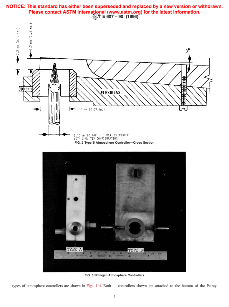
FIG. 2 Type B Atmosphere Controller—Cross Section
FIG. 3 Nitrogen Atmosphere Controllers
types of atmosphere controllers are shown in Figs. 1-4. Both controllers shown are attached to the bottom of the Petrey
NOTICE: This standard has either been superseded and replaced by a new version or withdrawn.
Please contact ASTM International (www.astm.org) for the latest information.
E607–90 (1996)
FIG. 4 Direct-Reading Chart
TABLE 1 Precision Data
chamber body and up into the analytical gap. The Type B
Relative Standard atmosphere controller employs two gas jets aimed directly at
Element Concentration, %
A,B
Deviation
the electrode. The gas flow is not restricted at either end of the
Silicon 1.2 1.0
chamber.
12.1 1.4
6.4.3 Gas Flow System—PracticeE 406E 406providesgen-
18.3 1.9
Copper 0.5 1.4 eralrecommendationsconcerningtheintroductionofgasesand
4.5 1.2
the variables involved in handling gases.
Magnesium 1.2 1.3
6.4.3.1 A typical gas flow system would include a 6400-L
2.7 1.4
Zinc 0.02 5.3
(226 ft ) capacity nitrogen tank, a two-stage regulator with
5.0 1.5
pressure gages, flow metering valves, flow indicators (0 to 720
Iron 0.1 1.0
L/h),asolenoid-orlever-type-operatedcut-offvalve,andvinyl
0.8 1.4
Manganese 0.005 1.2
tubing for transferring the gas from the regulatingsystem to the
1.2 1.0
atmosphere controller. The solenoid valve is used as part of an
Sodium 0.0002 6.3
automatic control system which allows for controlling the gas
A
Relative standard deviation, RSD, %, is calculated as follows:
purge time, extinguishing the fatigue lamp, starting the source
¯
RSD,% 5 ~100/ X!=(d /~n 2 1!
unit, and stopping the gas flow at the end of the exposure time.
where:
Refer to Practice E 406E 406.
¯
X = average concentration, %.
6.5 Spectrometer, having characteristics equivalent to those
d = difference between individual results and their average, and
n = number of individual results. listed in Table 2.
B
6.6 Measuring System, consisting of photomultipliers with
These precisions are for single day-operator-machine analysis.
individual dynode voltage adjustment, capacitors on which the
5 output of each photomultiplier is stored, an amplifier and
stand. The TypeAcontroller employs two gas jets which give
recording system suitable for registering a function of the
a tangential flow of the gas and consists of a cap to restrict the
capacitor voltages, and the necessary switching arrangements
flow of gas to the excitation region.The gas passes through the
to provide the desired sequence of operation. There may be
provision for switching pairs of zero and gain controls into the
Available through Angstrom, Inc., Belleville, MI. amplifier circuit.
NOTICE: This standard has either been superseded and replaced by a new version or withdrawn.
Please contact ASTM International (www.astm.org) for the latest information.
E607–90 (1996)
TABLE 2 Spectrometer Characteristics
8.3 Standardants—Aluminum materials of high uniformity
A B A
Type A Type B Type C that contain appropriate amounts of various elements. Their
exact chemical composition and metallurgical structure need
Focal length, m 1.5 1.5 2.0
Concave grating, 1000 1000 1000
not be known, but they must respond in a consistent manner to
grooves/mm, nominal
permit correcting for drift. It is appropriate to use the high-
Reciprocal linear dispersion 6.95 6.95 5.2
˚ purity aluminum as a “low’’ standardant.
A/mm
Primary slit width, µm 50 50 50
8.4 Verifiers—Aluminum materials used to determine if an
Secondary slit width, µm 150 150 150
instrument requires restandardization. They may also be used
Focal length, condensing 20 13 23
as standardants.
lens, cm, approx.
˚
Wavelength coverage, A 2000 to 8000 2100 to 6800 1966 to 8750
Maximum number of 35 40 68 9. Preparation of Samples
photomultiplier
9.1 Chill-Cast Disks—Refer to Practices E 716E 716.
A
A 1.5-m Production Control Quantometer (Type A), a 1.5-m Industrial Re-
searchQuantometer(TypeB),ora2-mProductionControlQuantometer(TypeC),
10. Preparation of Apparatus
manufactured byApplied Research Laboratories, Sunland, Calif., has been found
suitable for this purpose.
NOTE 1—The instructions given herein apply to most spectrometers.
However, some settings and adjustments may need to be varied and,
depending on the particular equipment, additional preparation of the
equipment may be required. For a description and further details of
6.6.1 The voltage adjustment for each photomultiplier shall
operation of a particular spectrometer, refer to the manufacturer’s hand-
control its output. The rheostat used for this purpose may be
book.
referred to as the attenuator.
10.1 Program the spectrometer to accommodate the internal
6.6.2 More than one readout channel may be needed for
standard line and analytical lines listed in Table 3 (Note 2).
each photomultiplier if the readout is controlled with gain and
Connect the photomultipliers, capacitors, and related measur-
zero controls. This permits defining more than one concentra-
ing system.
tion range for an element.
6.6.3 For an instrument using a fixed integration time, as is
NOTE 2—The lines listed have proven satisfactory for the elements and
typical in a computer readout, the ratio of the radiant energy of
concentration ranges described in the Scope. Other internal standard and
analytical lines may be used, provided it is shown that the results obtained
the analytical line to that of the internal standard will be
are comparable.
calculated from the voltages developed on the integrators. For
an instrument in which integration is controlled by the internal 10.1.1 Position or test the position of the spectrometer exit
standard, the reading displayed for each channel will be, in
slits, secondary mirrors, and photomultipliers to ensure that the
effect, a relative ratio of radiant energy. In a special application peak radiation passes through each slit and is focused on the
with a strip-chart recorder, the chart paper may be graduated in
photomultipliers. This shall be done initially and as often as
units of concentration. necessary thereafter to maintain proper alignment.
NOTE 3—The manner and frequency of positioning or checking the
7. Materials
positionoftheexitslitsandmirrorswilldependonfactorssuchasthetype
7.1 Counter Electrodes,ahigh-puritygraphiterod,6.15mm
of spectrometer, the variety of analytical problems, and the frequency of
use. Each laboratory should establish a suitable check procedure.
(0.242 in.) in diameter.
7.2 Nitrogen Gas—The gas should have a minimum purity
10.2 Electrical Parameters—The parameters for a typical
of 99.996 %. The cylinder should be replaced when the
source are listed here. For more information, refer to Practice
pressure reaches 689 kPa (100 psi).
E 172E 172.
High-Voltage Spark:
8. Reference Materials
Capacitance, µF 0.007
Inductance, µH 360
8.1 Calibrants—Analyzed aluminum materials that are ho-
Resistance in series with gap, V residual
mogeneous and free from voids or porosity. If not of similar
Peak potential, output, V 20,000
Primary potential, V 240 to 260
metallurgical condition to the samples being analyzed, they
Radio-frequency current, A (Note 4)9.0 6 0.1
may be used if it has been established that their responses are
Discharges/s 240
consistent with the specimens being analyzed. Calibrants are
NOTE 4—At maximum intervals of 4 h, excite the high-purity standar-
available in a variety of compositions. Some have nominal
dant and set the radio-frequency current by adjusting t
...
Questions, Comments and Discussion
Ask us and Technical Secretary will try to provide an answer. You can facilitate discussion about the standard in here.