

ASTM D8328-24
(Test Method)Standard Test Method for Dynamic Testing of Powders Using the Freeman Technology FT4 Powder Rheometer
General Information
- Abstract
SIGNIFICANCE AND USE
5.1 The test can be used to evaluate the following:
5.1.1 Classification or comparison of powders—There are several parameters that can be used to classify powders relative to each other: AEv, ARv, BFE, CBD, CE, CI, FRI, NAS, PDv, SE and SI.
5.1.2 Sensitivity analysis—Dynamic tests can be used to evaluate the relative effects of a range of powder properties or environmental parameters, or both, such as (but not limited to) humidity, particle size and size distribution, particle shape and shape distribution, moisture content and temperature.
5.2 Quality control—The test can, in some circumstances, be used to assess the flow properties of a feedstock, intermediate or product against pre-determined acceptance criteria.
5.3 Process design and operation—The determined parameters can be used to quantify powder behavior in numerous processing environments. The determined parameters may also be used to quantify the effect of changing process parameters on powder flowability, including (but not limited to) shear rate during mixing, water addition during granulation and temperature during drying.
Note 1: The quality of the result produced by this test method is dependent on the competence of the personnel performing it, and the suitability of the equipment and facilities used. Agencies that meet the criteria of Practice D3740 are generally considered capable of competent and objective testing/sampling/inspection/etc. Users of this test method are cautioned that compliance with Practice D3740 does not in itself assure reliable results. Reliable results depend on many factors; Practice D3740 provides a means of evaluating some of those factors. Additional guidance on sampling of powders is given in Reference (1).
Practice D3740 was developed for agencies engaged in the testing and/or inspection of soil and rock. As such it is not totally applicable to agencies performing this test method. However, users of this test method should recognize that the framework ...
SCOPE
1.1 This method covers the apparatus and procedures for quantifying the dynamic flow properties of a fixed volume of powder or other bulk solid as a function of its resistance to being moved by a specially designed blade within a cylindrical test vessel, where the test specimen has an unconstrained upper surface. This allows for the resistance to motion to be assessed as ‘work done’ or energy measurement.
1.2 The parameters generated during this test are most commonly used to assist with the design and operation of powder processing and transport operations. They can also provide relative classification or comparison of the flow behavior of different powders, or different batches of the same powder, that are subjected to similar stress and flow regimes within their processing equipment.
1.3 The 50 mm apparatus described in this standard is suitable for measuring the properties of powders and other bulk solids with a maximum particle size of 6 mm. It is practicable to test powders which have a small proportion of particles between 6-10 mm, but it is recommended they represent no more than 5 % of the total mass with a normal (Gaussian) size distribution.
1.4 All observed and calculated values shall conform to the guidelines for significant digits and rounding established in Practice D6026.
1.4.1 The procedures used to specify how data are collected/recorded or calculated, in this standard, are regarded as the industry standard. In addition, they are representative of the significant digits that generally should be retained. The procedures used do not consider material variation, purpose for obtaining the data, special purpose studies, or any considerations for the user’s objectives; and it is common practice to increase or decrease significant digits of reported data to be commensurate with these considerations. It is beyond the scope of this standard to consider significant digits used in analysis methods for ...
- Status
- Published
- Publication Date
- 14-Mar-2024
- Technical Committee
- D18 - Soil and Rock
- Drafting Committee
- D18.24 - Characterization and Handling of Powders and Bulk Solids
Overview
ASTM D8328-24: Standard Test Method for Dynamic Testing of Powders Using the Freeman Technology FT4 Powder Rheometer provides a comprehensive laboratory procedure for quantifying the dynamic flow properties of powders and other bulk solids. The standard guides users in measuring powder resistance to motion under defined conditions using the FT4 Powder Rheometer, a specialized device that assesses how powders respond to being moved by a blade in a cylindrical container. These insights are valuable for classifying powders, evaluating the impact of environmental or material variations, and supporting powder processing design, operation, and quality control.
The method is suitable for powders and granular materials with a maximum particle size of 6 mm (with limited presence of particles up to 10 mm). The generated results create a foundation for optimizing powder handling, transport, and storage in various industries.
Key Topics
- Powder Classification and Comparison: The method allows for classifying and comparing powders using key parameters such as Basic Flowability Energy (BFE), Conditioned Bulk Density (CBD), Consolidated Energy (CE), Consolidation Index (CI), Flow Rate Index (FRI), Specific Energy (SE), Stability Index (SI), Aerated Energy (AEv), Aeration Ratio (ARv), Normalized Aeration Sensitivity (NAS), Pressure Drop (PDv).
- Sensitivity Analysis: Dynamic testing can reveal how variables like humidity, particle size and distribution, particle shape, moisture content, and temperature influence powder flow properties.
- Quality Control: The procedure can be integrated into quality assurance programs to assess the flow characteristics of raw materials, intermediates, or finished products, ensuring they meet predetermined acceptance criteria.
- Process Design Support: Data from dynamic testing help process engineers quantify powder behavior under varying shear rates, granulation conditions, and drying temperatures, among other process variables.
- Standardized Reporting: The standard prescribes the use of SI units and significant digits consistent with best industry practices, ensuring results are reliable and comparable.
Applications
Industrial Relevance:
This ASTM dynamic testing method is essential for industries such as pharmaceuticals, food processing, chemicals, and materials manufacturing, where powder flow behavior influences processing efficiency, product quality, and equipment design. Key applications include:
- Formulation Development: Selecting powders with optimal flow characteristics to support efficient blending, granulation, or tableting operations.
- Material Handling: Designing hoppers, silos, and conveyors based on reliable powder flow data to minimize blockages and segregation.
- Quality Assurance: Implementing routine assessments of incoming materials or final products to maintain process consistency and compliance with product specifications.
- Troubleshooting: Investigating issues related to poor flow, caking, or inconsistent processing outcomes by systematically evaluating changes in flow properties.
- Process Optimization: Adjusting process conditions based on test data to improve throughput, reduce downtime, and enhance product performance.
Related Standards
For users of ASTM D8328-24, familiarity with the following referenced standards and guidelines is beneficial:
- ASTM D653: Terminology Relating to Soil, Rock, and Contained Fluids
- ASTM D2216: Test Methods for Laboratory Determination of Water (Moisture) Content of Soil and Rock by Mass
- ASTM D3740: Practice for Minimum Requirements for Agencies Engaged in Testing and/or Inspection of Soil and Rock as Used in Engineering Design and Construction
- ASTM D6026: Practice for Using Significant Digits and Data Records in Geotechnical Data
These documents underpin accurate, repeatable powder flow analysis and support consistent implementation of dynamic powder rheometry in the laboratory.
Keywords: dynamic powder testing, FT4 Powder Rheometer, ASTM D8328-24, powder flow properties, powder classification, process design, quality control, bulk solids rheology, industrial powder processing, powder characterization.
Frequently Asked Questions
ASTM D8328-24 is a standard published by ASTM International. Its full title is "Standard Test Method for Dynamic Testing of Powders Using the Freeman Technology FT4 Powder Rheometer". This standard covers: SIGNIFICANCE AND USE 5.1 The test can be used to evaluate the following: 5.1.1 Classification or comparison of powders—There are several parameters that can be used to classify powders relative to each other: AEv, ARv, BFE, CBD, CE, CI, FRI, NAS, PDv, SE and SI. 5.1.2 Sensitivity analysis—Dynamic tests can be used to evaluate the relative effects of a range of powder properties or environmental parameters, or both, such as (but not limited to) humidity, particle size and size distribution, particle shape and shape distribution, moisture content and temperature. 5.2 Quality control—The test can, in some circumstances, be used to assess the flow properties of a feedstock, intermediate or product against pre-determined acceptance criteria. 5.3 Process design and operation—The determined parameters can be used to quantify powder behavior in numerous processing environments. The determined parameters may also be used to quantify the effect of changing process parameters on powder flowability, including (but not limited to) shear rate during mixing, water addition during granulation and temperature during drying. Note 1: The quality of the result produced by this test method is dependent on the competence of the personnel performing it, and the suitability of the equipment and facilities used. Agencies that meet the criteria of Practice D3740 are generally considered capable of competent and objective testing/sampling/inspection/etc. Users of this test method are cautioned that compliance with Practice D3740 does not in itself assure reliable results. Reliable results depend on many factors; Practice D3740 provides a means of evaluating some of those factors. Additional guidance on sampling of powders is given in Reference (1). Practice D3740 was developed for agencies engaged in the testing and/or inspection of soil and rock. As such it is not totally applicable to agencies performing this test method. However, users of this test method should recognize that the framework ... SCOPE 1.1 This method covers the apparatus and procedures for quantifying the dynamic flow properties of a fixed volume of powder or other bulk solid as a function of its resistance to being moved by a specially designed blade within a cylindrical test vessel, where the test specimen has an unconstrained upper surface. This allows for the resistance to motion to be assessed as ‘work done’ or energy measurement. 1.2 The parameters generated during this test are most commonly used to assist with the design and operation of powder processing and transport operations. They can also provide relative classification or comparison of the flow behavior of different powders, or different batches of the same powder, that are subjected to similar stress and flow regimes within their processing equipment. 1.3 The 50 mm apparatus described in this standard is suitable for measuring the properties of powders and other bulk solids with a maximum particle size of 6 mm. It is practicable to test powders which have a small proportion of particles between 6-10 mm, but it is recommended they represent no more than 5 % of the total mass with a normal (Gaussian) size distribution. 1.4 All observed and calculated values shall conform to the guidelines for significant digits and rounding established in Practice D6026. 1.4.1 The procedures used to specify how data are collected/recorded or calculated, in this standard, are regarded as the industry standard. In addition, they are representative of the significant digits that generally should be retained. The procedures used do not consider material variation, purpose for obtaining the data, special purpose studies, or any considerations for the user’s objectives; and it is common practice to increase or decrease significant digits of reported data to be commensurate with these considerations. It is beyond the scope of this standard to consider significant digits used in analysis methods for ...
SIGNIFICANCE AND USE 5.1 The test can be used to evaluate the following: 5.1.1 Classification or comparison of powders—There are several parameters that can be used to classify powders relative to each other: AEv, ARv, BFE, CBD, CE, CI, FRI, NAS, PDv, SE and SI. 5.1.2 Sensitivity analysis—Dynamic tests can be used to evaluate the relative effects of a range of powder properties or environmental parameters, or both, such as (but not limited to) humidity, particle size and size distribution, particle shape and shape distribution, moisture content and temperature. 5.2 Quality control—The test can, in some circumstances, be used to assess the flow properties of a feedstock, intermediate or product against pre-determined acceptance criteria. 5.3 Process design and operation—The determined parameters can be used to quantify powder behavior in numerous processing environments. The determined parameters may also be used to quantify the effect of changing process parameters on powder flowability, including (but not limited to) shear rate during mixing, water addition during granulation and temperature during drying. Note 1: The quality of the result produced by this test method is dependent on the competence of the personnel performing it, and the suitability of the equipment and facilities used. Agencies that meet the criteria of Practice D3740 are generally considered capable of competent and objective testing/sampling/inspection/etc. Users of this test method are cautioned that compliance with Practice D3740 does not in itself assure reliable results. Reliable results depend on many factors; Practice D3740 provides a means of evaluating some of those factors. Additional guidance on sampling of powders is given in Reference (1). Practice D3740 was developed for agencies engaged in the testing and/or inspection of soil and rock. As such it is not totally applicable to agencies performing this test method. However, users of this test method should recognize that the framework ... SCOPE 1.1 This method covers the apparatus and procedures for quantifying the dynamic flow properties of a fixed volume of powder or other bulk solid as a function of its resistance to being moved by a specially designed blade within a cylindrical test vessel, where the test specimen has an unconstrained upper surface. This allows for the resistance to motion to be assessed as ‘work done’ or energy measurement. 1.2 The parameters generated during this test are most commonly used to assist with the design and operation of powder processing and transport operations. They can also provide relative classification or comparison of the flow behavior of different powders, or different batches of the same powder, that are subjected to similar stress and flow regimes within their processing equipment. 1.3 The 50 mm apparatus described in this standard is suitable for measuring the properties of powders and other bulk solids with a maximum particle size of 6 mm. It is practicable to test powders which have a small proportion of particles between 6-10 mm, but it is recommended they represent no more than 5 % of the total mass with a normal (Gaussian) size distribution. 1.4 All observed and calculated values shall conform to the guidelines for significant digits and rounding established in Practice D6026. 1.4.1 The procedures used to specify how data are collected/recorded or calculated, in this standard, are regarded as the industry standard. In addition, they are representative of the significant digits that generally should be retained. The procedures used do not consider material variation, purpose for obtaining the data, special purpose studies, or any considerations for the user’s objectives; and it is common practice to increase or decrease significant digits of reported data to be commensurate with these considerations. It is beyond the scope of this standard to consider significant digits used in analysis methods for ...
ASTM D8328-24 is available in PDF format for immediate download after purchase. The document can be added to your cart and obtained through the secure checkout process. Digital delivery ensures instant access to the complete standard document.
Standards Content (Sample)
This international standard was developed in accordance with internationally recognized principles on standardization established in the Decision on Principles for the
Development of International Standards, Guides and Recommendations issued by the World Trade Organization Technical Barriers to Trade (TBT) Committee.
Designation: D8328 − 24
Standard Test Method for
Dynamic Testing of Powders Using the Freeman Technology
FT4 Powder Rheometer
This standard is issued under the fixed designation D8328; the number immediately following the designation indicates the year of
original adoption or, in the case of revision, the year of last revision. A number in parentheses indicates the year of last reapproval. A
superscript epsilon (´) indicates an editorial change since the last revision or reapproval.
1. Scope 1.5 Units—The values stated in SI units are to be regarded
as standard. No other units of measure are included in this
1.1 This method covers the apparatus and procedures for
standard. Reporting of test results in units other than SI shall
quantifying the dynamic flow properties of a fixed volume of
not be regarded as nonconformance with this standard.
powder or other bulk solid as a function of its resistance to
1.6 This standard does not purport to address all of the
being moved by a specially designed blade within a cylindrical
safety concerns, if any, associated with its use. It is the
test vessel, where the test specimen has an unconstrained upper
responsibility of the user of this standard to establish appro-
surface. This allows for the resistance to motion to be assessed
priate safety, health, and environmental practices and deter-
as ‘work done’ or energy measurement.
mine the applicability of regulatory limitations prior to use.
1.2 The parameters generated during this test are most
1.7 This international standard was developed in accor-
commonly used to assist with the design and operation of
dance with internationally recognized principles on standard-
powder processing and transport operations. They can also
ization established in the Decision on Principles for the
provide relative classification or comparison of the flow
Development of International Standards, Guides and Recom-
behavior of different powders, or different batches of the same
mendations issued by the World Trade Organization Technical
powder, that are subjected to similar stress and flow regimes
Barriers to Trade (TBT) Committee.
within their processing equipment.
1.3 The 50 mm apparatus described in this standard is
2. Referenced Documents
suitable for measuring the properties of powders and other bulk
2.1 ASTM Standards:
solids with a maximum particle size of 6 mm. It is practicable
D653 Terminology Relating to Soil, Rock, and Contained
to test powders which have a small proportion of particles
Fluids
between 6-10 mm, but it is recommended they represent no
D2216 Test Methods for Laboratory Determination of Water
more than 5 % of the total mass with a normal (Gaussian) size
(Moisture) Content of Soil and Rock by Mass
distribution.
D3740 Practice for Minimum Requirements for Agencies
1.4 All observed and calculated values shall conform to the
Engaged in Testing and/or Inspection of Soil and Rock as
guidelines for significant digits and rounding established in
Used in Engineering Design and Construction
Practice D6026.
D6026 Practice for Using Significant Digits and Data Re-
1.4.1 The procedures used to specify how data are collected/
cords in Geotechnical Data
recorded or calculated, in this standard, are regarded as the
industry standard. In addition, they are representative of the
3. Terminology
significant digits that generally should be retained. The proce-
3.1 Definitions—For definitions of common technical terms
dures used do not consider material variation, purpose for
used in this standard, refer to Terminology D653.
obtaining the data, special purpose studies, or any consider-
3.2 Definitions of Terms Specific to This Standard:
ations for the user’s objectives; and it is common practice to
3.2.1 Aerated Energy, AE , n—in storing, handling and
increase or decrease significant digits of reported data to be
v
processing bulk solids using industrial equipment, the flow
commensurate with these considerations. It is beyond the scope
energy of a powder at a controlled superficial gas velocity of v
of this standard to consider significant digits used in analysis
mm/s traversing upwards through the powder bed.
methods for engineering design.
This test method is under the jurisdiction of ASTM Committee D18 on Soil and
Rock and is the direct responsibility of Subcommittee D18.24 on Characterization For referenced ASTM standards, visit the ASTM website, www.astm.org, or
and Handling of Powders and Bulk Solids. contact ASTM Customer Service at service@astm.org. For Annual Book of ASTM
Current edition approved March 15, 2024. Published April 2024. DOI: 10.1520/ Standards volume information, refer to the standard’s Document Summary page on
D8328-24. the ASTM website.
Copyright © ASTM International, 100 Barr Harbor Drive, PO Box C700, West Conshohocken, PA 19428-2959. United States
D8328 − 24
3.2.1.1 Discussion—Calculation for AE described in 3.2.10.1 Discussion—Calculation for FRI described in
v
11.4.2. 11.3.4.
3.2.2 Aeration Ratio, AR , n—in storing, handling and
3.2.11 Normalized Aeration Sensitivity, NAS, n—in storing,
v
processing bulk solids using industrial equipment, the ratio of
handling and processing bulk solids using industrial
flow energy of a powder with zero gas flow to that of the same
equipment, the maximum rate of change in flow energy with
powder when gas is passed upwards through the powder bed at respect to a controlled, variable, superficial gas flow traversing
a controlled superficial gas velocity of v mm/s.
upwards through the powder bed.
3.2.2.1 Discussion—Calculation for AR described in
3.2.11.1 Discussion—Calculation for NAS described in
v
11.4.3.
11.4.4.
3.2.3 Basic Flowability Energy, BFE, n—in storing, han-
3.2.12 Pressure Drop, PD —in storing, handling and pro-
v
dling and processing bulk solids using industrial equipment,
cessing bulk solids using industrial equipment, the pressure
the flow energy of a powder measured during the seventh test
difference across the powder bed resulting from the passage of
cycle of a dynamic test.
a controlled, superficial gas flow traversing the test specimen at
3.2.3.1 Discussion—Calculation for BFE described in
v mm/s.
11.3.2.
3.2.12.1 Discussion—Determination of PD described in
v
11.4.5.
3.2.4 Conditioned Bulk Density, CBD, n—in storing, han-
dling and processing bulk solids using industrial equipment,
3.2.13 Specific Energy, SE, n—in storing, handling and
the bulk density of a test specimen of powder after condition-
processing bulk solids using industrial equipment, the resis-
ing.
tance to motion of a specialized blade traversing upwards
3.2.4.1 Discussion—Calculation for CBD described in
through an unconfined powder bed following a prescribed
11.3.3.
pathway and represented as a flow energy per unit mass (mJ/g).
3.2.5 conditioning, v—in storing, handling and processing 3.2.13.1 Discussion—Calculation for SE described in
bulk solids using industrial equipment, the process of homog- 11.3.5.
enizing the state of consolidation of a powder test specimen by
3.2.14 Stability Index, SI, n—in storing, handling and pro-
use of a specialized blade attachment.
cessing bulk solids using industrial equipment, the ratio of flow
3.2.6 Consolidated Energy, CE, n—in storing, handling and
energy of a powder after one test to that after n tests where
processing bulk solids using industrial equipment, the flow
conditioning is completed between each test cycle.
energy of a powder consolidated by controlled tapping.
3.2.14.1 Discussion—Calculation for SI described in 11.3.6.
3.2.6.1 Discussion—Calculation for CE described in 11.4.6.
3.2.15 test cycle, n—in storing, handling and processing
3.2.7 Consolidation Index, CI, n—in storing, handling and
bulk solids using industrial equipment, a section of a dynamic
processing bulk solids using industrial equipment, the ratio of
test where the specialized blade completes both a downwards
flow energy of a consolidated powder to that of the same
and upwards traverse through a precise volume of conditioned
powder prior to consolidation.
powder following a prescribed pathway.
3.2.7.1 Discussion—Calculation for CI described in 11.4.7.
4. Summary of Test Method
3.2.8 dynamic test, n—in storing, handling and processing
bulk solids using industrial equipment, a test used to quantify
4.1 Selection of the Appropriate Testing Regime—The par-
the flow properties of a fixed volume of powder or other bulk
ticular stress and flow regimes used to evaluate the flow
solid in motion.
properties of the test specimen may depend on the reason for
3.2.8.1 Discussion—The measurement consists of multiple
generating the data, as outlined in Section 5, and should
test cycles during which the powder’s resistance to being
broadly reflect the stresses that the powder is subjected to in its
moved by a specially designed blade is measured as a function
processing environment.
of external variables such as introduced gas flow and consoli-
4.2 Measurement of Flow Energy—The specialized blade
dation.
attachment is used to traverse the test specimen through a
3.2.9 flow energy, n—in storing, handling and processing
prescribed path at a pre-determined speed. The torque and
bulk solids using industrial equipment, the resistance to motion
force required to maintain the motion of the blade are recorded
of a specialized blade as it traverses downwards through a
with respect to the axial position of the blade at a suitable
precise volume of confined, conditioned powder following a
measurement interval.
prescribed pathway and represented as an energy.
4.3 Measurement of PD —The resistance of the powder bed
3.2.9.1 Discussion—Calculation for flow energy described v
to the passage of controlled gas flow is recorded by means of
in 11.2.
a computer-controlled Aeration Control Unit (ACU) as a
3.2.10 Flow Rate Index, FRI, n—in storing, handling and
superficial gas velocity of v mm/s is maintained.
processing bulk solids using industrial equipment, the ratio of
flow energy of a powder after a test at one blade tip speed to a
5. Significance and Use
test at a different blade tip speed where conditioning is
completed in between each test cycle. 5.1 The test can be used to evaluate the following:
D8328 − 24
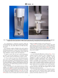
FIG. 1 FT4 Powder Rheometer (The left hand image shows the instrument with the specialized blade attachment fitted; the right hand
image shows a test vessel (50 mm × 160 mL split vessel) (containing a test specimen) and the specialized blade.)
guidance on sampling of powders is given in Reference (1).
5.1.1 Classification or comparison of powders—There are
Practice D3740 was developed for agencies engaged in the testing
several parameters that can be used to classify powders relative
and/or inspection of soil and rock. As such it is not totally applicable to
to each other: AE , AR , BFE, CBD, CE, CI, FRI, NAS, PD ,
v v v
agencies performing this test method. However, users of this test method
SE and SI.
should recognize that the framework of Practice D3740 is appropriate for
5.1.2 Sensitivity analysis—Dynamic tests can be used to evaluating the quality of an agency performing this practice. Currently
there is no known qualifying national authority that inspects agencies that
evaluate the relative effects of a range of powder properties or
perform this test method.
environmental parameters, or both, such as (but not limited to)
humidity, particle size and size distribution, particle shape and
6. Apparatus
shape distribution, moisture content and temperature.
6.1 The FT4 Powder Rheometer is shown in Fig. 1. It is a
5.2 Quality control—The test can, in some circumstances,
computer-controlled instrument which simultaneously mea-
be used to assess the flow properties of a feedstock, interme-
sures the torque and force required to mobilize a powder
diate or product against pre-determined acceptance criteria.
contained in a range of vessel types. This allows for the
5.3 Process design and operation—The determined param-
generation of powder characteristics such as dynamic flow
eters can be used to quantify powder behavior in numerous
properties, including aeration behavior, shear properties, wall
processing environments. The determined parameters may also
friction, permeability and compressibility of test specimens,
be used to quantify the effect of changing process parameters
using a series of spindle-mounted attachments driven by an
on powder flowability, including (but not limited to) shear rate
electric motor located on a carriage, driven by another electric
during mixing, water addition during granulation and tempera-
motor, which moves the attachments in the vertical direction.
ture during drying.
6.1.1 The force is measured by a force transducer located
NOTE 1—The quality of the result produced by this test method is
beneath and fixed to the table that supports the test vessel
dependent on the competence of the personnel performing it, and the
suitability of the equipment and facilities used. Agencies that meet the during the measurement process.
criteria of Practice D3740 are generally considered capable of competent
6.1.2 The torque (shear resistance) is evaluated by measur-
and objective testing/sampling/inspection/etc. Users of this test method
ing the moment on the attachment using a torque transducer.
are cautioned that compliance with Practice D3740 does not in itself
Both torque and force are measured with respect to the axial
assure reliable results. Reliable results depend on many factors; Practice
D3740 provides a means of evaluating some of those factors. Additional position of the blade within the test vessel.
D8328 − 24
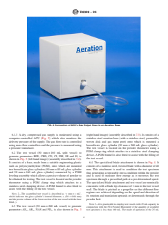
FIG. 2 Connection of ACU’s Gas Output Hose to an Aeration Base
6.1.3 A dry, compressed gas supply is moderated using a (right hand image) (assembly described in 7.3). It consists of a
computer-controlled ACU (Fig. 2) which also monitors the stainless steel aeration base (with a stainless steel, permeable,
delivery pressure of the supply. The gas flow rate is controlled woven disk and gas input port) onto which is mounted a
using mass flow controllers and the pressure is measured using borosilicate glass cylinder (50 mm × 260 mL glass cylinder).
a pressure transducer. The test vessel is located on the powder rheometer using a
POM clamp ring which attaches to a stainless steel clamping
6.2 The test vessel (50 mm × 160 mL split vessel) to
device. A POM funnel is also fitted to assist with the filling of
generate parameters BFE, CBD, CE, CI, FRI, SE and SI, is
the test vessel.
shown in Fig. 3 (left hand image) (assembly described in 7.2).
It consists of a base, made from a suitable engineering plastic
6.4 The specialized blade attachment is shown in Fig. 4. It
such as polyoxymethylene (POM), onto which are mounted consists of a stainless steel, twisted blade with a diameter of 48
two borosilicate glass cylinders (50 mm × 85 mL glass cylinder
mm. This attachment is used to condition the test specimen
and 50 mm × 160 mL glass cylinder) connected by a POM thus generating a repeatable stress condition within the powder
leveling assembly which allows a precise volume of powder to
and is used to measure flow energy as it traverses the test
be obtained for testing. The test vessel is located on the powder specimen through a prescribed path at a pre-determined speed.
rheometer using a POM clamp ring which attaches to a
The specialized blade attachment and test vessel are nominally
stainless steel clamping device. A POM funnel is also fitted to concentric with a blade tip clearance of 1 mm to the test vessel
assist with the filling of the test vessel.
wall. The blade is pitched as a propeller so that different flow
regimes are achieved depending on the speed and direction of
NOTE 2—The assembled test vessel is described as ‘x mm × y mL’,
its rotation and translation upwards or downwards through the
which indicates the glass cylinder’s internal diameter, x, (50 6 0.04 mm)
powder bed.
and the precise volume of the lower section of the test vessel with the base
fitted, y.
NOTE 3—It is practicable to employ test vessels with 25 mL capacity in
6.3 The test vessel (50 mm × 260 mL vessel) to generate
conjunction with the FT4 Powder Rheometer if the quantity of available
parameters AE , AR , NAS and PD , is also shown in Fig. 3 test specimen is less than 160 mL. The mode of operation of the 25 mL
v v v
D8328 − 24
FIG. 3 Test Vessels (The left hand image shows the test vessel (50 mm × 160 mL split vessel) for generating parameters BFE, CBD, CE,
CI, FRI, SE and SI; the right hand image shows the test vessel (50 mm × 260 mL vessel) for generating parameters AE , AR , NAS and
v v
PD .)
v
FIG. 4 Specialized Blade Attachment for Conditioning the Test Specimen and Measuring flow Energy as It Traverses the Test Specimen
through a Prescribed Path at a Pre-determined Speed
test vessels is identical to that described herein for the 50 mm × 160 mL maximum particle size is commensurately reduced to a maximum particle
split vessel and 50 mm × mL vessel but using a smaller test vessel with a size of 3 mm.
diameter of 25 mm and a 23.5 mm diameter blade. The limit on the
D8328 − 24
FIG. 5 Components to Assemble the 50 mm × 160 mL Split Vessel (4mm ball-ended hex key not shown)
6.5 A thermometric device and hygrometer are advised to base to make sure that the entire circumference is in contact
measure temperature and humidity as referenced in 10.4. with the glass cylinder (Fig. 8).
7.2.3 Open the leveling assembly and place it on top of the
6.6 An automated tapping device shall be used as a source
glass cylinder at the opposite end to the clamp ring and base
of consolidation for the determination of CE and CI.
(orientation shown in Fig. 9). Make sure that the gap in the
leveling assembly is approximately aligned with the text
7. Preparation of Apparatus
printed on the glass cylinder.
7.1 Make sure that the test vessels and specialized blade are
7.2.4 Carefully invert the glass cylinder, clamp ring, base
undamaged, clean and free from grease and other contaminants
and leveling assembly and place on the edge of a flat surface
(2).
(Fig. 10) so that the glass cylinder can be fitted flush with the
NOTE 4—Since the integrity of the specialized blade attachment is
inner face of the leveling assembly without impediment from
critical to generating accurate and reliable data, it should be handled with
the upper part of the leveling assembly and in the correct
care and studied for damage at regular intervals.
orientation (3).
7.2 Assembly of Test Vessel (50 mm × 160 mL split vessel)
7.2.5 Push down gently on both the glass cylinder and the
for the determination of BFE, CBD, CE, CI, FRI, SE and
leveling assembly so that they are both flush with the flat
SI—The following items are required to assemble the test
surface.
vessel (50 mm × 160 mL split vessel): a 50 mm × 85 mL glass
7.2.6 Tighten the leveling assembly with the ball-ended hex
cylinder; a 50 mm × 160 mL glass cylinder; a 50 mm diameter
key such that the leveling assembly and the glass cylinder are
POM base fitted with an O-ring; a 50 mm diameter clamp ring;
securely located.
a 50 mm diameter leveling assembly; a 50 mm diameter funnel
7.2.7 Confirm that the glass cylinder and leveling assembly
and a 4 mm ball-ended hex key. With the exception of the 4
are flush, and check that the leveling assembly operates
mm ball-ended hex key, these items are shown in Fig. 5.
smoothly.
NOTE 5—A fully detailed assembly procedure is also available (3). 7.2.8 Close the leveling assembly.
7.2.9 Place the 50 mm × 85 mL glass cylinder into the top
7.2.1 To assemble the test vessel (50 mm × 160 mL split
half of the leveling assembly and gently rotate the upper glass
vessel), position the clamp ring approximately 1 mm from the
cylinder to make sure that it is in contact with the glass cylinder
end of the 50 mm × 160 mL glass cylinder (Fig. 6) and loosely
below.
fit the clamp ring onto the glass cylinder (Fig. 7). The clamp
7.2.10 Tighten the leveling assembly with the ball-ended
ring must not project past the end of the glass cylinder;
hex key such that the leveling assembly and the upper glass
otherwise misalignment may occur. Make sure that the gap in
cylinder are securely located (Fig. 11).
the clamp ring is approximately centralized with the printing
on the glass cylinder. Secure the clamp ring using the ball- 7.2.11 Place the funnel on top of the assembled test vessel
ended hex key, ensuring that the screw is not over tightened. and locate on the FT4 Powder Rheometer ensuring that the
7.2.2 Locate the POM base fitted with an O-ring into the platform is free from obstruction and the test vessel is level
glass cylinder adjacent to the clamp ring. Carefully rotate the (Fig. 12).
D8328 − 24
FIG. 6 Positioning the Clamp Ring Approximately 1 mm from the End of the 50 mm × 160 mL Glass Cylinder
FIG. 7 Fitting the Clamp Ring to the 50 mm × 160 mL Glass Cylinder with the Ball-Ended Hex Key
NOTE 6—A fully detailed assembly procedure is also available (3).
7.3 Assembly of Test Vessel (50 mm × 260 mL vessel) for the
determination of AE , AR , NAS 317 and PD —The following
v v v
7.3.1 To assemble the test vessel (50 mm × 260 mL vessel),
items are required to assemble the test vessel (50 mm × 260
position the clamp ring approximately 1 mm from the end of
mL vessel): a 50 mm × 260 mL glass cylinder; a 50 mm
the 50 mm × 260 mL glass cylinder (Fig. 14) and loosely fit the
diameter stainless steel aeration base fitted with an O-ring; a 50
clamp ring onto the glass cylinder (Fig. 15). The clamp ring
mm diameter clamp ring; a 50 mm diameter funnel and a 4 mm
must not project past the end of the glass cylinder; otherwise
ball-ended hex key. With the exception of the 4 mm ball-ended
misalignment may occur. Make sure that the gap in the clamp
hex key, these items are shown in Fig. 13.
D8328 − 24
9. Conditioning
9.1 Preparation of the specimen for the determination of
BFE, CBD, FRI, SE and SI—Add the test specimen to the test
vessel and its mass is automatically determined using the
instrument’s built-in balance. Initiate the automated test
program, it runs independently of the operator other than to use
a leveling assembly. The test specimen first undergoes condi-
tioning using the specialized blade attachment which reduces
variability in packing density introduced during filling of the
test vessel or from the material’s previous history. Excess
powder must then be removed from the test cell by means of a
leveling assembly to leave a controlled volume of conditioned
powder with a level surface that is ready for dynamic testing.
The leveling assembly must then be closed, and the test
initiated.
9.2 Preparation of the specimen for the determination of
AE , AR , NAS and PD —Add the test specimen to the test
v v v
vessel which is attached to an ACU. Initiate the automated test
program, it runs independently of the operator. The test
specimen first undergoes two conditioning cycles using the
specialized blade attachment to reduce any variability in
packing density introduced during filling or from the material’s
previous history. A controlled gas flow at a superficial velocity
of 2 mm/s is supplied by the ACU without operator input, and
the test is initiated.
9.3 Preparation of the specimen for the determination of CE
FIG. 8 Fitting the POM Base with O-ring onto the 50 mm × 160
and CI—Add the test specimen to the test vessel and its mass
mL Glass Cylinder
is automatically determined using the instrument’s built-in
balance. Initiate the automated test program, it runs indepen-
dently of the operator other than to use a leveling assembly and
to consolidate the test specimen. The test specimen first
ring is approximately aligned with the text printed on the glass
undergoes conditioning using the specialized blade attachment
cylinder. Secure the clamp ring using the ball-ended hex key.
which reduces any variability in packing density introduced
7.3.2 Locate the stainless steel, aeration base fitted with an
during filling or from the material’s previous history. Remove
O-ring into the glass cylinder adjacent to the clamp ring.
the test vessel from the instrument and consolidate the powder.
Carefully rotate the base to make sure that the entire circum-
Reintroduce the test vessel to the instrument and remove
ference is in contact with the glass cylinder (Fig. 16).
excess powder from the test vessel by means of a leveling
7.3.3 Place the funnel on top of the assembled test vessel assembly to leave a controlled volume of consolidated powder
and locate on the FT4 Powder Rheometer ensuring that the with a level surface that is ready for dynamic testing. The
platform is free from obstruction and the test vessel is level leveling assembly must then be closed, and the test initiated.
(Fig. 17).
10. Procedure
7.3.4 Connect the ACU’s gas output hose to the aeration
10.1 Measurement procedure for determination of BFE,
base.
CBD, FRI, SE and SI parameters:
NOTE 7—The assembled test vessel is described as a 50 mm × 260 mL
10.1.1 Select the appropriate test program from the program
vessel assembly, which indicates the glass cylinder’s internal diameter and
library.
the precise volume of the test vessel with the base fitted.
NOTE 9—Once selected, the test program displays images of the test
8. Calibration vessel and attachment that are advised to commence the test.
NOTE 10—There is an automated test program available which is based
8.1 Apparatus—Calibrate and verify the instrument accord-
on an initial conditioning cycle followed by the removal of the excess
ing to the manufacturer’s instructions. The manufacturer’s
powder using the leveling assembly. Through instrument automation this
is followed by seven conditioning and test cycles using a blade tip speed
recommended verification frequency is 90 days.
of 100 mm/s, then four conditioning and test cycles using blade tip speeds
NOTE 8—The force and torque transducers located within the instru-
of 100, 70, 40 and 10 mm/s. This program is called a ‘stability and
ment are calibrated using proprietary fixtures in conjunction with calibra-
variable flow rate’ test. The test method can be modified in detail with
tion masses that are supplied with the instrument (4). Force should be
respect to number of test and conditioning cycles are undertaken.
calibrated within the instrument’s performance limits of 650 N, and
10.1.2 Securely fasten the assembled 50 mm × 160 mL split
torque should be calibrated within the performance limits of 6900 mNm,
vessel (7.2) to the instrument table using the stainless steel
both to tolerances better than 1.0 %. The Mass Flow Controllers fitted to
the ACU and the pressure transducer are calibrated by the manufacturer. clamping assembly (Fig. 12).
D8328 − 24
FIG. 9 Positioning the Leveling Assembly with Respect to the 50 mm × 160 mL Glass Cylinder
FIG. 10 Fitting the Leveling Assembly onto the 50 mm × 160 mL Glass Cylinder with the Ball-Ended Hex Key
10.1.3 Tare (zero) the mass of the empty test vessel using 10.1.5 Push the start button on the computer screen to
the built-in balance prior to filling with the test specimen. commence the test program.
10.1.4 Once tared, fill the test vessel with sufficient powder
NOTE 12—This automatically causes the blade to be slowly lowered
such that, following conditioning, the test specimen does not
into the test vessel, after which it performs conditioning by traversing
fall below the split level of the leveling assembly.
through the powder along a prescribed helical path. When the test program
is initiated, the mass of the test specimen is registered within the data file
NOTE 11—If the level of the powder is below the level of the leveling
associated with the test.
assembly following conditioning, the test is classified as a failure and
re-run with a greater starting volume. NOTE 13—Though instrument automation, during conditioning the
...