

oSIST prEN 12516-3:2025
(Main)Industrial valves - Shell design strength - Part 3: Experimental method
- Abstract
This document specifies requirements for an experimental method to prove that representative samples of valve shells and their body ends, made in cast iron, steel or copper alloy materials, are designed to possess the required pressure containing capability, with an adequate margin of safety.
This document is not applicable to valves designed for use in the creep range (time-dependent design), or to valves designed for cyclic pressure applications (fatigue design).
For valves in the scope of the European legislation for pressure equipment, the sole use of an experimental method is only permitted when the maximum allowable pressure at room temperature, PS, multiplied by the DN-number is less than 3 000 bar. This document is used to supplement the tabulation method EN 12516-1:2014+A1:2018, and the calculation method EN 12516-2:2014+A1:2021 without limit.
- Status
- Not Published
- Public Enquiry End Date
- 02-Nov-2025
- Technical Committee
- TLP - Pressure vessels
- Current Stage
- 4020 - Public enquire (PE) (Adopted Project)
- Start Date
- 10-Sep-2025
- Due Date
- 28-Jan-2026
- Completion Date
- 23-Oct-2025

oSIST prEN 12516-3:2025 is a draft European Standard from CEN on the experimental method for proving the shell design strength of industrial valves. It sets out how representative valve shells and body ends in cast iron, steel, or copper alloy are hydrostatically tested at room temperature to show adequate pressure-containing capability with a safety margin.
What does oSIST prEN 12516-3:2025 specify?
oSIST prEN 12516-3:2025 specifies an experimental method for proving the pressure-containing capability of representative samples of valve shells and their body ends. It applies to cast iron, steel, and copper alloy materials, and it is meant to be used alongside the tabulation and calculation methods in the EN 12516 series.
The document excludes valves designed for creep conditions and valves designed for cyclic pressure applications where fatigue governs. For valves within the scope of the Pressure Equipment Directive, sole use of the experimental method is only permitted when PS multiplied by DN is less than 3 000 bar.
The document is organized into Scope, Normative references, Terms and definitions, Symbols, Description of test, Test method, and Acceptance criteria. It also includes two informative annexes.
| Annex | What it covers |
|---|---|
| Annex A | The origin of the experimental test factor, C, and the background to the elevated test philosophy |
| Annex ZA | The relationship between this European Standard and Directive 2014/68/EU |
What are the key requirements of oSIST prEN 12516-3:2025?
oSIST prEN 12516-3:2025 ties the test pressure to the actual shell geometry and the actual material strength, so the test reflects the sample being examined rather than only a nominal design. In practice, that means the manufacturer must measure wall thickness, verify material certificates, and calculate the test pressure from the stated formulas in Clause 6.
Test setup and sample condition
Clause 5 requires the valve body ends to be closed with suitable sealing shells matched to the body-end type, such as flanges, threaded plugs, or welded caps. The test equipment must not load the shell externally or reinforce it in a way that could change the result, because the test is meant to demonstrate shell strength, not fixture strength.
Wall thickness and material verification
Clause 6.1 requires the shell thickness to match the minimum requirements on the manufacturing drawing, and measured thickness is checked at all specified locations. Where only a general thickness is shown, at least three locations are checked, and very local thickness readings in areas smaller than 10 DN mm are ignored when calculating the wall-thickness ratio X.
Clause 6.2 requires the material test certificates for each shell to be checked against the material specification. The actual proof strength is then compared with the minimum specified proof strength to obtain the ratio Y, which shows whether the test pressure should be increased for stronger-than-minimum material.
Experimental test pressure
Clause 6.3 uses the experimental test factor C together with X and Y to calculate the body and bonnet or cover pressures separately. The lower calculated pressure is applied first, then the higher pressure, or the higher pressure may be applied directly for the minimum duration.
The same clause also allows the experimental method to be omitted when a shell has already been shown by EN 12516-1 or EN 12516-2 to have the required pressure-containing capability at at least the same PS. If PS is given only at elevated temperature, the pressure calculation is adjusted for that temperature.
Time, records, and acceptance
Clause 6.4 sets a minimum test duration of 10 min. Clause 6.5 requires full documentation of the test, including parameters and results, so the assessment can be traced later.
Clause 7 rejects any visually detectable leakage from an external shell surface. Leakage at the body-bonnet/cover joint is treated differently and does not by itself justify rejection, and a different gasket may be used if needed to judge the integrity of the shell components.
What terms does oSIST prEN 12516-3:2025 define?
- Shell - the pressure-containing envelope of the valve, normally including the body and, where designed in, the bonnet or cover and their joint excluding sealing parts.
- Experimental test pressure - the internal gauge pressure, in bar, applied to the valve during the test.
- Test fluid - the pressurized liquid used for the test, namely water.
- Test fluid temperature - the permitted water temperature range for the test, from 5 °C to 40 °C.
- Maximum allowable pressure (PS) - the pressure value used in the test-pressure calculation and in the scope limit for pressure equipment.
- Experimental test factor (C) - the material-related factor used to calculate the elevated hydrostatic test pressure.
Who uses oSIST prEN 12516-3:2025?
oSIST prEN 12516-3:2025 is used by valve designers, manufacturers, test laboratories, and quality teams that need a reproducible way to prove shell strength. It is especially relevant in the industrial valves and pressure equipment sectors, where body ends, shell thickness, material certificates, and test records all affect acceptance.
It is also used by conformity assessment and compliance staff working with Directive 2014/68/EU, because Annex ZA links the normative clauses to the essential requirements on adequate strength and experimental design method.
What changed in oSIST prEN 12516-3:2025 from the previous edition?
oSIST prEN 12516-3:2025 supersedes EN 12516-3:2002 and EN 12516-3:2002/AC 2003. The changes stated in the foreword are editorial revisions in some parts, updated normative references, and a revised Annex ZA.
Which standards are used with oSIST prEN 12516-3:2025?
oSIST prEN 12516-3:2025 cites EN 736-2:2016 and EN 736-3:2008 as normative references. These provide the valve terminology and component definitions used in the document, so the test language is tied to common valve definitions.
The foreword and introduction also identify the related parts of the EN 12516 series. EN 12516-1 provides the tabulation method for steel valve shells, EN 12516-2 provides the calculation method for steel valve shells, and EN 12516-4 covers calculation for valve shells made in metallic materials other than steel. oSIST prEN 12516-3:2025 is the experimental method part of that series.
What does the oSIST prEN 12516-3:2025 document contain?
oSIST prEN 12516-3:2025 contains a symbol table, a test description, a calculation-based test method, and acceptance criteria. It also includes Table 2 for the experimental test factor C and Annex A, which explains the background to those factors and gives comparison and safety-factor tables.
The document provides formulas for wall-thickness ratio, material-strength ratio, and experimental test pressure for the body and for the bonnet or cover. Those formulas are used for design verification and for planning the pressure test.
Annex ZA maps Clauses 5, 6, and 7.1 to the relevant essential requirements of Directive 2014/68/EU. This is the part used when the standard is applied for pressure-equipment conformity work.
Relations
- Referred By
SIST EN ISO 18750:2025 - Intelligent transport systems - Local dynamic map (ISO 18750:2025) - Effective Date
- 28-Jan-2026
- Effective Date
- 28-Jan-2026
- Effective Date
- 28-Jan-2026
- Referred By
SIST-TS CEN/TS 17496:2021 - Cooperative intelligent transport systems - Communication profiles - Effective Date
- 28-Jan-2026
- Effective Date
- 28-Jan-2026
- Effective Date
- 28-Jan-2026
- Effective Date
- 01-Oct-2025
- Effective Date
- 01-Oct-2025
Get Certified
Connect with accredited certification bodies for this standard

Institut za varilstvo d.o.o. (Welding Institute)
Slovenia's leading welding institute since 1952. ISO 3834, EN 1090, pressure equipment certification, NDT personnel, welder qualification. Only IIW Au
Sponsored listings
Frequently Asked Questions
oSIST prEN 12516-3:2025 is a draft published by the Slovenian Institute for Standardization (SIST). Its full title is "Industrial valves - Shell design strength - Part 3: Experimental method". This standard covers: This document specifies requirements for an experimental method to prove that representative samples of valve shells and their body ends, made in cast iron, steel or copper alloy materials, are designed to possess the required pressure containing capability, with an adequate margin of safety. This document is not applicable to valves designed for use in the creep range (time-dependent design), or to valves designed for cyclic pressure applications (fatigue design). For valves in the scope of the European legislation for pressure equipment, the sole use of an experimental method is only permitted when the maximum allowable pressure at room temperature, PS, multiplied by the DN-number is less than 3 000 bar. This document is used to supplement the tabulation method EN 12516-1:2014+A1:2018, and the calculation method EN 12516-2:2014+A1:2021 without limit.
This document specifies requirements for an experimental method to prove that representative samples of valve shells and their body ends, made in cast iron, steel or copper alloy materials, are designed to possess the required pressure containing capability, with an adequate margin of safety. This document is not applicable to valves designed for use in the creep range (time-dependent design), or to valves designed for cyclic pressure applications (fatigue design). For valves in the scope of the European legislation for pressure equipment, the sole use of an experimental method is only permitted when the maximum allowable pressure at room temperature, PS, multiplied by the DN-number is less than 3 000 bar. This document is used to supplement the tabulation method EN 12516-1:2014+A1:2018, and the calculation method EN 12516-2:2014+A1:2021 without limit.
oSIST prEN 12516-3:2025 is classified under the following ICS (International Classification for Standards) categories: 23.060.01 - Valves in general. The ICS classification helps identify the subject area and facilitates finding related standards.
oSIST prEN 12516-3:2025 has the following relationships with other standards: It is inter standard links to SIST EN ISO 18750:2025, SIST EN ISO 17419:2025, SIST-TS CEN ISO/TS 24315-3:2025, SIST-TS CEN/TS 17496:2021, SIST-TS CEN ISO/TS 21184:2021, SIST EN ISO 17423:2025, SIST EN 12516-3:2003/AC:2004, SIST EN 12516-3:2003. Understanding these relationships helps ensure you are using the most current and applicable version of the standard.
oSIST prEN 12516-3:2025 is associated with the following European legislation: EU Directives/Regulations: 2014/68/EU; Standardization Mandates: M/071, M/601. When a standard is cited in the Official Journal of the European Union, products manufactured in conformity with it benefit from a presumption of conformity with the essential requirements of the corresponding EU directive or regulation.
oSIST prEN 12516-3:2025 is available in PDF format for immediate download after purchase. The document can be added to your cart and obtained through the secure checkout process. Digital delivery ensures instant access to the complete standard document.
Standards Content (Sample)
SLOVENSKI STANDARD
01-oktober-2025
Industrijski ventili - Trdnost ohišja - 3. del: Eksperimentalna metoda
Industrial valves - Shell design strength - Part 3: Experimental method
Industriearmaturen - Gehäusefestigkeit - Teil 3: Experimentelles Verfahren
Robinetterie industrielle - Résistance mécanique des enveloppes - Partie 3: Méthode
expérimentale
Ta slovenski standard je istoveten z: prEN 12516-3
ICS:
23.060.01 Ventili na splošno Valves in general
2003-01.Slovenski inštitut za standardizacijo. Razmnoževanje celote ali delov tega standarda ni dovoljeno.
DRAFT
EUROPEAN STANDARD
prEN 12516-3
NORME EUROPÉENNE
EUROPÄISCHE NORM
August 2025
ICS Will supersede EN 12516-3:2002
English Version
Industrial valves - Shell design strength - Part 3:
Experimental method
Robinetterie industrielle - Résistance mécanique des Industriearmaturen - Gehäusefestigkeit - Teil 3:
enveloppes - Partie 3: Méthode expérimentale Experimentelles Verfahren
This draft European Standard is submitted to CEN members for enquiry. It has been drawn up by the Technical Committee
CEN/TC 69.
If this draft becomes a European Standard, CEN members are bound to comply with the CEN/CENELEC Internal Regulations
which stipulate the conditions for giving this European Standard the status of a national standard without any alteration.
This draft European Standard was established by CEN in three official versions (English, French, German). A version in any other
language made by translation under the responsibility of a CEN member into its own language and notified to the CEN-CENELEC
Management Centre has the same status as the official versions.
CEN members are the national standards bodies of Austria, Belgium, Bulgaria, Croatia, Cyprus, Czech Republic, Denmark, Estonia,
Finland, France, Germany, Greece, Hungary, Iceland, Ireland, Italy, Latvia, Lithuania, Luxembourg, Malta, Netherlands, Norway,
Poland, Portugal, Republic of North Macedonia, Romania, Serbia, Slovakia, Slovenia, Spain, Sweden, Switzerland, Türkiye and
United Kingdom.
Recipients of this draft are invited to submit, with their comments, notification of any relevant patent rights of which they are
aware and to provide supporting documentation.
Warning : This document is not a European Standard. It is distributed for review and comments. It is subject to change without
notice and shall not be referred to as a European Standard.
EUROPEAN COMMITTEE FOR STANDARDIZATION
COMITÉ EUROPÉEN DE NORMALISATION
EUROPÄISCHES KOMITEE FÜR NORMUNG
CEN-CENELEC Management Centre: Rue de la Science 23, B-1040 Brussels
© 2025 CEN All rights of exploitation in any form and by any means reserved Ref. No. prEN 12516-3:2025 E
worldwide for CEN national Members.
prEN 12516-3:2025 (E)
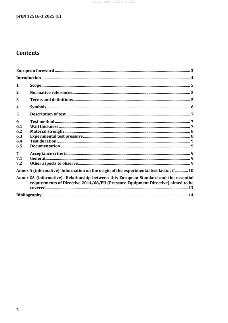
Contents
European foreword . 3
Introduction . 4
1 Scope . 5
2 Normative references . 5
3 Terms and definitions . 5
4 Symbols . 6
5 Description of test . 7
6 Test method . 7
6.1 Wall thickness . 7
6.2 Material strength . 8
6.3 Experimental test pressure . 8
6.4 Test duration . 9
6.5 Documentation . 9
7 Acceptance criteria. 9
7.1 General. 9
7.2 Other aspects to observe . 9
Annex A (informative) Information on the origin of the experimental test factor, C . 10
Annex ZA (informative) Relationship between this European Standard and the essential
requirements of Directive 2014/68/EU (Pressure Equipment Directive) aimed to be
covered . 13
Bibliography . 14
prEN 12516-3:2025 (E)
European foreword
This document (prEN 12516-3:2025) has been prepared by Technical Committee CEN/TC 69 “Industrial
valves”, the secretariat of which is held by AFNOR.
This document is currently submitted to the CEN Enquiry.
This document will supersede EN 12516-3:2002 and EN 12516-3:2002/AC 2003.
prEN 12516-3:2025 includes the following changes with respect to EN 12516-3:2002 and
EN 12516-3:2002/AC 2003:
— some parts were editorially revised;
— the normative references were updated;
— Annex ZA was (revised) modified.
This document has been prepared under a standardization request addressed to CEN by the European
Commission. The Standing Committee of the EFTA States subsequently approves these requests for its
Member States.
For the relationship with EU Legislation, see informative Annex ZA, which is an integral part of this
document.
EN 12516 series consists of the following parts:
— EN 12516-1, Industrial valves — Shell design strength — Part 1: Tabulation method for steel valve
shells
— EN 12516-2, Industrial valves — Shell design strength — Part 2: Calculation method for steel valve
shells
— EN 12516-3, Industrial valves — Shell design strength — Part 3: Experimental method
— EN 12516-4, Industrial valves — Shell design strength — Part 4: Calculation method for valve shells
manufactured in metallic materials other than steel
prEN 12516-3:2025 (E)
Introduction
This document establishes an experimental method of assessing the strength of valve shells by applying
an elevated hydrostatic pressure test at room temperature.
The experimental test factor, C, for use in the equation to determine the elevated hydrostatic test
pressure, takes into account the ductility of the various materials. Information on the origin of the
experimental test factor, C, is given in Annex A.
This document may be used as an alternative method to those specified in EN 12516-1:2014+A1:2018
(tabulation method) or EN 12516-2:2014+A1:2021 (calculation method) within the limits specified in
the scope.
prEN 12516-3:2025 (E)
1 Scope
This document specifies requirements for an experimental method to prove that representative samples
of valve shells and their body ends, made in cast iron, steel or copper alloy materials, are designed to
possess the required pressure containing capability, with an adequate margin of safety.
This document is not applicable to valves designed on the basis of time dependent strength values (creep)
or valves designed for pulsating pressure applications (fatigue).
For valves in the scope of the European legislation for pressure equipment, the sole use of an
experimental method is only permitted when the maximum allowable pressure at room temperature, PS,
multiplied by the DN-number is less than 3 000 bar. This document is used to supplement the tabulation
method EN 12516-1:2014+A1:2018, and the calculation method EN 12516-2:2014+A1:2021 without
limit.
2 Normative references
The following documents are referred to in the text in such a way that some or all of their content
constitutes requirements of this document. For dated references, only the edition cited applies. For
undated references, the latest edition of the referenced document (including any amendments) applies.
EN 736-2:2016, Valves - Terminology - Part 2: Definition of components of valves
EN 736-3:2008, Valves - Terminology - Part 3: Definition of terms
3 Terms and definitions
For the purposes of this document, the terms and definitions given in EN 736-2:2016 and EN 736-3:2008
and the following apply.
ISO and IEC maintain terminology databases for use in standardization at the following addresses:
— ISO Online browsing platform: available at https://www.iso.org/obp/
— IEC Electropedia: available at https://www.electropedia.org/
3.1
shell
pressure containing envelope of the valve
Note 1 to entry: It normally comprises the body and when included in the design a bonnet or cover and the body
bonnet or body cover joint excluding sealing parts.
[SOURCE: EN 736-2:2016, 3.1]
3.2
experimental test pressure
internal pressure (gauge), expressed in bar to which the valve under testing is subjected
Note 1 to entry: Unless otherwise noted, gauge pressure is used throughout this document.
3.3
test fluid
pressurized liquid (water) used to test a valve
prEN 12516-3:2025 (E)
3.4
test fluid temperature
temperature of the test fluid, ≥ 5 °C and ≤ 40 °C
4 Symbols
Table 1 — Symbols and units
Symbol Unit Description
A % is the percentage elongation after fracture
C — is the experimental test factor
Cb — is the experimental test factor for the body
C — is the experimental test factor for the bonnet or cover
bc
e mm is the measured wall thickness
mes
e mm is the minimum specified drawing wall thickness
min
K — is the factor for calculating of the experimental test pressure p
t, exp
K — is the K for the body
b
K — is the K for the bonnet or cover
bc
p bar is the design pressure
PS bar is the maximum allowable pressure
PS bar is the maximum allowable pressure at room temperature
RT
PS bar is the maximum allowable pressure at temperature t
t
p bar is the experimental test pressure
t, exp
p bar is the experimental test pressure at room temperature
t, exp/RT
p bar is the experimental test pressure at room temperature for the body
t, exp b/RT
p bar is the experimental test pressure at room temperature for the bonnet or cover
t, exp bc/RT
p” bar is the elevated test pressure used for type testing of series-manufactured valves
R N/mm is the tensile strength at room temperature
m/RT
R N/mm is the 1,0 % proof strength
p1,0
R N/mm is the actual 0,2 % proof strength at room temperature
p0,2 act/RT
R N/mm is the minimum 0,2 % proof strength at room temperature specified in the
p0,2 min/RT
appropriate material standard
R N/mm is the minimum 0,2 % proof strength at temperature t specified in the appropriate
p0,2 min/t
material standard
S — is the safety factor
S” — is the safety factor depending on the material
X — is the ratio of e to e
mes min
X — is the maximum value of X for the body
b max
X — is the maximum value of X for the bonnet or cover
bc max
prEN 12516-3:2025 (E)
Symbol Unit Description
Y — is the ratio of R /R
p0,2 act/RT p0,2 min/RT
Y — is the Y for the body
b
Y — is the Y for the bonnet or cover
bc
5 Description of test
The valve body ends shall be closed using suitable sealing shells, e.g. flanges, threaded plugs, welded caps
etc. corresponding to the type of body ends.
The test equipment shall be of such a design, that it does not subject the shell to externally applied loads
and does not apply any reinforcement to the shells, which may affect the results of the tests.
NOTE 1 The test equipment can apply external loads sufficient to react to the forces resulting from the test
pressure.
The test pressure shall be applied to the
...