

prEN 14367
(Main)Non controllable backflow preventer with different pressure zones - Family C, type A
General Information
- Abstract
This document specifies the:
— field of application:
— The dimensional, the physicochemical, the design, the hydraulic, the mechanical and the acoustic characteristics of non-controllable backflow preventer with different pressure zones, family C, type A, nominal sizes DN 6 to DN 25, nominal pressure PN 10.
It is applicable to:
— Family C, type A, class “a” for general use: devices of class “a” can be capable of working:
— at any pressure up to 1 MPa (10 bar);
— with any pressure variation up to 1 MPa (10 bar);
— at a supply temperature limit of 65 °C and 90 °C for 1 h;
— Family C, type A, class “b” for specific use: devices of class “b” shall be capable of working:
— at any downstream pressure up to 0,3 MPa (3 bar);
— with any downstream pressure variation up to 0,3 MPa (3 bar); at a supply temperature limit of 65 °C and 90 °C for 1 h;
Class “b” devices can capable of operating: at any downstream pressure up to 300 kPa (3 bar), with any downstream pressure variation up to 300 kPa (3 bar) at a supply temperature limit of 65 °C and 90 °C for 1 h. Class “b” devices with specific hydraulic and non-acoustic requirements and are intended to equip filling devices physically integrated into a single-function (heating) or dual-function (heating and domestic hot water) boiler.
It specifies also:
— test methods and requirements for verifying these characteristics;
— marking;
— presentation and the delivery.
- Status
- Not Published
- Publication Date
- 03-May-2027
- Technical Committee
- CEN/TC 164 - Water supply
- Current Stage
- 4020 - Submission to enquiry - Enquiry
- Start Date
- 09-Jul-2026
- Due Date
- 16-Dec-2025
- Completion Date
- 09-Jul-2026

Overview
prEN 14367:2026 defines the requirements for non-controllable backflow preventers with different pressure zones, classified as Family C, Type A. Developed by CEN/TC 164 for water supply systems, this standard addresses devices in nominal sizes DN 6 to DN 25 with a nominal pressure of PN 10. These devices are designed to prevent the reverse flow of water, protecting potable water installations from pollution due to backflow. The scope covers both general use (class "a") and specific use (class "b") devices, including their design, materials, test methods, marking, and delivery requirements.
Key Topics
Device Classification and Application
- Class "a": General use, suitable for pressures up to 1 MPa (10 bar) and supply temperatures up to 65 °C (occasionally up to 90 °C for 1 hour)
- Class "b": Specific use for integrated functions in heating or mixed domestic hot water boilers, operating at downstream pressures up to 0.3 MPa (3 bar) with the same temperature limits as class "a"
Technical Requirements
- Dimensional, hydraulic, mechanical, physicochemical, and acoustic properties are specified
- Materials must be safe for contact with potable water and resistant to corrosion, including the requirement for dezincification-resistant copper alloys
- Devices must ensure functional performance after exposure to pressure, temperature, and cycles tested in controlled environments
Design and Construction
- The standard mandates fixed, non-adjustable spring mechanisms and non-removable components for certain device types
- Relief valves require positive safety operation, and air breaks to drain are compulsory to prevent contamination
- Marking and documentation for traceability and compliance are required for each device
Performance and Testing
- Detailed test methods for mechanical resistance, hydraulic behavior, tightness, acoustic performance, and endurance
- Reference to standardized test procedures for laboratory assessments
- Devices must not exhibit leakage, deformation, or deterioration after endurance and reliability testing
Applications
Non-controllable backflow preventers are essential in protecting drinking water supplies. Their typical applications include:
Residential and Commercial Water Installations
- Ensuring the integrity of potable water systems by preventing backflow contamination from connected equipment or secondary systems
Heating and Hot Water Systems
- Particularly for class "b" devices, integrated within single-function (heating) or dual-function (heating and domestic hot water) boilers to prevent cross-contamination during system filling or operation
Industrial and Public Buildings
- Used wherever back-siphonage or backpressure risks exist, including laboratories, hospitals, or venues with complex water networks
The devices are designed for reliability across varying pressures and temperatures, with emphasis on safety and minimal maintenance throughout their operational lifespan.
Related Standards
For comprehensive compliance and system integration, prEN 14367 refers to several supporting standards:
- EN 1717: Protection against pollution of water intended for human consumption in potable water installations; general requirements for devices to prevent backflow.
- EN 1254 series: Requirements for copper and copper alloy plumbing fittings.
- EN 1267: Industrial valves - Test of flow resistance using water.
- EN ISO 228-1 & EN ISO 3822: Pipe threads and acoustic testing methods for water supply fittings.
- EN ISO 6509-1: Determination of dezincification resistance in brass.
Adherence to these standards ensures proper selection, installation, and maintenance of backflow preventers for water supply safety and regulatory compliance.
By following prEN 14367, stakeholders in water supply and building services engineering can ensure methods and devices for backflow prevention are consistent, reliable, and aligned with European best practices for potable water protection.
Relations
- Revises
EN 14367:2005 - Non controllable backflow preventer with different pressure zones - Family C, type A - Effective Date
- 19-Jan-2023
Get Certified
Connect with accredited certification bodies for this standard

DIBt (Deutsches Institut für Bautechnik)
German Institute for Building Technology.
DIN CERTCO
DIN Group product certification.

Aboma Certification B.V.
Specialized in construction, metal, and transport sectors.
Sponsored listings
Frequently Asked Questions
prEN 14367 is a draft published by the European Committee for Standardization (CEN). Its full title is "Non controllable backflow preventer with different pressure zones - Family C, type A". This standard covers: This document specifies the: — field of application: — The dimensional, the physicochemical, the design, the hydraulic, the mechanical and the acoustic characteristics of non-controllable backflow preventer with different pressure zones, family C, type A, nominal sizes DN 6 to DN 25, nominal pressure PN 10. It is applicable to: — Family C, type A, class “a” for general use: devices of class “a” can be capable of working: — at any pressure up to 1 MPa (10 bar); — with any pressure variation up to 1 MPa (10 bar); — at a supply temperature limit of 65 °C and 90 °C for 1 h; — Family C, type A, class “b” for specific use: devices of class “b” shall be capable of working: — at any downstream pressure up to 0,3 MPa (3 bar); — with any downstream pressure variation up to 0,3 MPa (3 bar); at a supply temperature limit of 65 °C and 90 °C for 1 h; Class “b” devices can capable of operating: at any downstream pressure up to 300 kPa (3 bar), with any downstream pressure variation up to 300 kPa (3 bar) at a supply temperature limit of 65 °C and 90 °C for 1 h. Class “b” devices with specific hydraulic and non-acoustic requirements and are intended to equip filling devices physically integrated into a single-function (heating) or dual-function (heating and domestic hot water) boiler. It specifies also: — test methods and requirements for verifying these characteristics; — marking; — presentation and the delivery.
This document specifies the: — field of application: — The dimensional, the physicochemical, the design, the hydraulic, the mechanical and the acoustic characteristics of non-controllable backflow preventer with different pressure zones, family C, type A, nominal sizes DN 6 to DN 25, nominal pressure PN 10. It is applicable to: — Family C, type A, class “a” for general use: devices of class “a” can be capable of working: — at any pressure up to 1 MPa (10 bar); — with any pressure variation up to 1 MPa (10 bar); — at a supply temperature limit of 65 °C and 90 °C for 1 h; — Family C, type A, class “b” for specific use: devices of class “b” shall be capable of working: — at any downstream pressure up to 0,3 MPa (3 bar); — with any downstream pressure variation up to 0,3 MPa (3 bar); at a supply temperature limit of 65 °C and 90 °C for 1 h; Class “b” devices can capable of operating: at any downstream pressure up to 300 kPa (3 bar), with any downstream pressure variation up to 300 kPa (3 bar) at a supply temperature limit of 65 °C and 90 °C for 1 h. Class “b” devices with specific hydraulic and non-acoustic requirements and are intended to equip filling devices physically integrated into a single-function (heating) or dual-function (heating and domestic hot water) boiler. It specifies also: — test methods and requirements for verifying these characteristics; — marking; — presentation and the delivery.
prEN 14367 is classified under the following ICS (International Classification for Standards) categories: 91.140.60 - Water supply systems. The ICS classification helps identify the subject area and facilitates finding related standards.
prEN 14367 has the following relationships with other standards: It is inter standard links to EN 14367:2005. Understanding these relationships helps ensure you are using the most current and applicable version of the standard.
prEN 14367 is associated with the following European legislation: EU Directives/Regulations: 305/2011. When a standard is cited in the Official Journal of the European Union, products manufactured in conformity with it benefit from a presumption of conformity with the essential requirements of the corresponding EU directive or regulation.
prEN 14367 is available in PDF format for immediate download after purchase. The document can be added to your cart and obtained through the secure checkout process. Digital delivery ensures instant access to the complete standard document.
Standards Content (Sample)
SLOVENSKI STANDARD
01-september-2026
Sistemski ločevalnik z različnimi nenadzorovanimi območji tlaka - Družina C, tip A
Non controllable backflow preventer with different pressure zones - Family C, type A
Systemtrenner mit unterschiedlichen nicht kontrollierbaren Druckzonen - Familie C, Typ
A
Disconnecteur non contrôlable à zones de pression différentes - Famille C, type A
Ta slovenski standard je istoveten z: prEN 14367
ICS:
91.140.60 Sistemi za oskrbo z vodo Water supply systems
2003-01.Slovenski inštitut za standardizacijo. Razmnoževanje celote ali delov tega standarda ni dovoljeno.
DRAFT
EUROPEAN STANDARD
NORME EUROPÉENNE
EUROPÄISCHE NORM
July 2026
ICS 91.140.60 Will supersede EN 14367:2005
English Version
Non controllable backflow preventer with different
pressure zones - Family C, type A
Disconnecteur non contrôlable à zones de pression Systemtrenner mit unterschiedlichen nicht
différentes - Famille C, type A kontrollierbaren Druckzonen - Familie C, Typ A
This draft European Standard is submitted to CEN members for enquiry. It has been drawn up by the Technical Committee
CEN/TC 164.
If this draft becomes a European Standard, CEN members are bound to comply with the CEN/CENELEC Internal Regulations
which stipulate the conditions for giving this European Standard the status of a national standard without any alteration.
This draft European Standard was established by CEN in three official versions (English, French, German). A version in any other
language made by translation under the responsibility of a CEN member into its own language and notified to the CEN-CENELEC
Management Centre has the same status as the official versions.
CEN members are the national standards bodies of Austria, Belgium, Bulgaria, Croatia, Cyprus, Czech Republic, Denmark, Estonia,
Finland, France, Germany, Greece, Hungary, Iceland, Ireland, Italy, Latvia, Lithuania, Luxembourg, Malta, Netherlands, Norway,
Poland, Portugal, Republic of North Macedonia, Romania, Serbia, Slovakia, Slovenia, Spain, Sweden, Switzerland, Türkiye and
United Kingdom.
Recipients of this draft are invited to submit, with their comments, notification of any relevant patent rights of which they are
aware and to provide supporting documentation.
Warning : This document is not a European Standard. It is distributed for review and comments. It is subject to change without
notice and shall not be referred to as a European Standard.
EUROPEAN COMMITTEE FOR STANDARDIZATION
COMITÉ EUROPÉEN DE NORMALISATION
EUROPÄISCHES KOMITEE FÜR NORMUNG
CEN-CENELEC Management Centre: Rue de la Science 23, B-1040 Brussels
© 2026 CEN All rights of exploitation in any form and by any means reserved Ref. No. prEN 14367:2026 E
worldwide for CEN national Members.
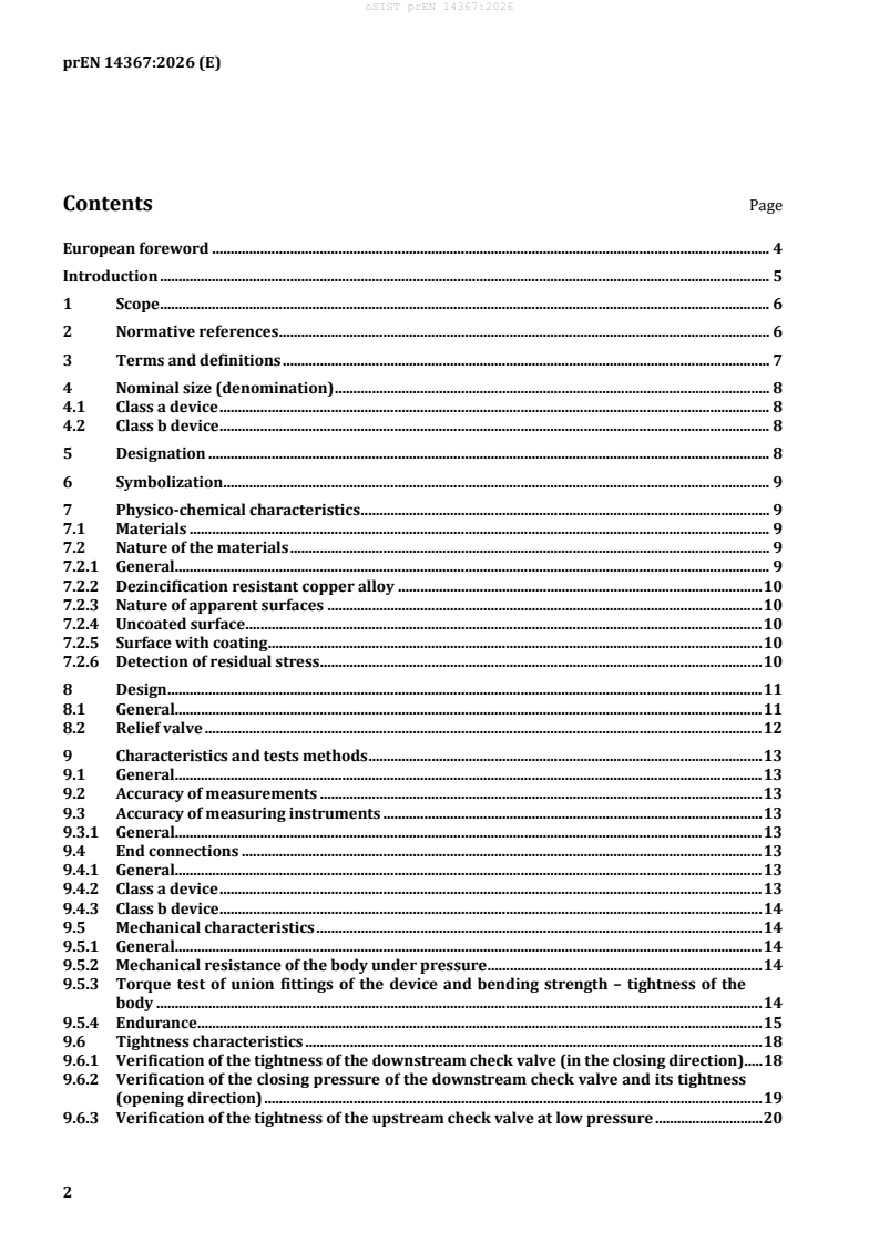
Contents Page
European foreword . 4
Introduction . 5
1 Scope . 6
2 Normative references . 6
3 Terms and definitions . 7
4 Nominal size (denomination) . 8
4.1 Class a device . 8
4.2 Class b device . 8
5 Designation . 8
6 Symbolization . 9
7 Physico-chemical characteristics . 9
7.1 Materials . 9
7.2 Nature of the materials . 9
7.2.1 General. 9
7.2.2 Dezincification resistant copper alloy . 10
7.2.3 Nature of apparent surfaces . 10
7.2.4 Uncoated surface . 10
7.2.5 Surface with coating . 10
7.2.6 Detection of residual stress . 10
8 Design . 11
8.1 General. 11
8.2 Relief valve . 12
9 Characteristics and tests methods . 13
9.1 General. 13
9.2 Accuracy of measurements . 13
9.3 Accuracy of measuring instruments . 13
9.3.1 General. 13
9.4 End connections . 13
9.4.1 General. 13
9.4.2 Class a device . 13
9.4.3 Class b device . 14
9.5 Mechanical characteristics . 14
9.5.1 General. 14
9.5.2 Mechanical resistance of the body under pressure . 14
9.5.3 Torque test of union fittings of the device and bending strength – tightness of the
body . 14
9.5.4 Endurance . 15
9.6 Tightness characteristics . 18
9.6.1 Verification of the tightness of the downstream check valve (in the closing direction) . 18
9.6.2 Verification of the closing pressure of the downstream check valve and its tightness
(opening direction) . 19
9.6.3 Verification of the tightness of the upstream check valve at low pressure . 20
9.6.4 Verification of the tightness of the upstream check valve under vacuum . 20
9.7 Hydraulic characteristics . 22
9.7.1 Test rig — General circuit . 22
9.7.2 Verification of the pressure loss as a function of the flow rate . 24
9.7.3 Verification of the opening (disconnection) and closing (tightness) of the relief valve . 24
9.7.4 Verification of the relief flow rate . 25
9.8 Compatibility with the products used for disinfection of the networks . 26
9.8.1 Requirement . 26
9.8.2 Test method . 26
9.9 Acoustic tests . 27
9.9.1 General . 27
9.9.2 Procedure . 27
10 Marking and technical documents . 27
10.1 Marking . 27
10.2 Technical documents . 28
11 Presentation at delivery . 28
Annex A (normative) Complementary test methods on backflow preventers CA class b with a
plastic body . 30
Annex B (informative) Order of Tests . 33
Bibliography . 35
European foreword
This document (prEN 14367:2026) has been prepared by Technical Committee CEN/TC 164 “Water
supply”, the secretariat of which is held by AFNOR.
This document is currently submitted to the CEN Enquiry.
This document will supersede EN 14367:2005.
— Scope was updated
— Accuracy chapter was added
— The whole systematic of testing and requirements was revised
— Annex B was deleted and replaced by a new one with order of tests
— All figures were updated
— Editorially revised
Introduction
In respect of potential adverse effects on the quality of water intended for human consumption, caused
by the product covered by this document:
a) This document provides no information as to whether the product might be used without
restriction in any of the Member States of the EU or EFTA.
b) while awaiting the adoption of verifiable European criteria, existing national regulations concerning
the use and/or the characteristics of this product remain in force.
1 Scope
This document specifies the:
— field of application:
— The dimensional, the physicochemical, the design, the hydraulic, the mechanical and the acoustic
characteristics of non-controllable backflow preventer with different pressure zones, family C,
type A, nominal sizes DN 6 to DN 25, nominal pressure PN 10.
It is applicable to:
— Family C, type A, class “a” for general use: devices of class “a” can be capable of working:
— at any pressure up to 1 MPa (10 bar);
— with any pressure variation up to 1 MPa (10 bar);
— at a supply temperature limit of 65 °C and 90 °C for 1 h;
— Family C, type A, class “b” for specific use: devices of class “b” shall be capable of working:
— at any downstream pressure up to 0,3 MPa (3 bar);
— with any downstream pressure variation up to 0,3 MPa (3 bar); at a supply temperature limit of
65 °C and 90 °C for 1 h;
Class “b” devices can capable of operating: at any downstream pressure up to 300 kPa (3 bar), with any
downstream pressure variation up to 300 kPa (3 bar) at a supply temperature limit of 65 °C and 90 °C
for 1 h. Class “b” devices with specific hydraulic and non-acoustic requirements and are intended to
equip filling devices physically integrated into a single-function (heating) or dual-function (heating and
domestic hot water) boiler.
It specifies also:
— test methods and requirements for verifying these characteristics;
— marking;
— presentation and the delivery.
2 Normative references
The following documents are referred to in the text in such a way that some or all of their content
constitutes requirements of this document. For dated references, only the edition cited applies. For
undated references, the latest edition of the referenced document (including any amendments) applies.
EN 1254 (all parts), Copper and copper alloys — Plumbing fittings
EN 1267, Industrial Valves — Test of flow resistance using water as test fluid
EN 1717, Protection against pollution of water intended for human consumption in potable water
installations and general requirements for devices to prevent pollution by backflow
EN ISO 228-1, Pipe threads where pressure-tight joints are not made on the threads — Part 1: Dimensions,
tolerances and designation (ISO 228-1)
EN ISO 3822-1:1999, Acoustics — Laboratory tests on noise emission from appliances and equipment used
in water supply installations — Part 1: Method of measurement (ISO 3822-1:1999)
EN ISO 3822-3:2018, Acoustics — Laboratory tests on noise emission from appliances and equipment used
in water supply installations — Part 3: Mounting and operating conditions for in line valves and
appliances(ISO 3822-3:2018)
EN ISO 6509-1, Corrosion of metals and alloys — Determination of dezincification resistance of brass
(ISO 6509-1:1981)
3 Terms and definitions
For the purposes of this document, the terms and definitions given in EN 1717 and the following apply.
ISO and IEC maintain terminology databases for use in standardization at the following addresses:
— ISO Online browsing platform: available at https://www.iso.org/obp/
— IEC Electropedia: available at https://www.electropedia.org/
3.1
non controllable backflow preventer with different pressure zones — Family C — Type A
the specific characteristics of this device called “CA”, are as follows:
The device is divided into three zones:
— one upstream zone p ;
— one intermediate zone (p not measurable) vented to the atmosphere;
i
— one downstream zone p .
The device provides disconnection by venting the intermediate pressure zone to the atmosphere when
the difference of pressure between the intermediate zone and the upstream zone is less than 10 % of
the upstream pressure (p – p < 10 % p )
i 1 1
It ensures a discharge (backflow rate) through the intermediate zone, at least equal to the given
discharge flow rate
Means for the control of the protection device are not included
Key
p
1 Upstream zone
p
2 Intermediate zone
i
p
3 Downstream zone
4 Strainer (optional)
Figure 1 — Design principle
For the purposes of this document “Non controllable backflow preventer with different pressure
zones — Family C — Type A” is hereafter referred to as “device”.
3.2
specific use
use of the backflow protection device at the filling point of domestic sealed heating systems, class b only
4 Nominal size (denomination)
4.1 Class a device
The nominal size shall be in accordance with the flow rate in the Table 3.
4.2 Class b device
All Class b devices shall comply with the same performances requirements as a DN 6.
5 Designation
A non-controllable backflow preventer with different pressure zones family C, type A is designated by:
— family, its type and class;
— denomination (see Table 3) except class b device;
— connection type;
— material of its body;
— surface finish (possible coating);
— acoustic group except class b device;
— reference to the present standard.
EXAMPLE
Examples for a designation:
class a:
— Non controllable backflow preventer with different pressure zones, EN 14367, family C, type
A, class a, DN 20, G3/4 × G3/4, bronze, I,
class b:
— Non controllable backflow preventer with different pressure zones, EN 14367, family C, type
A, class b, M10 × 1, brass,
6 Symbolization
The graphic representation of the non-controllable backflow preventer with different pressure zones —
family C, type A is as follows:
a) Class a b) Class b
Figure 2 — Graphic symbol
7 Physico-chemical characteristics
7.1 Materials
The selection of materials is the responsibility of the manufacturer, provided they satisfy the following
requirements:
a) materials and coatings shall not contaminate the potable water;
b) in a technical document, the nature of the materials and coatings used shall be stated;
c) materials with inadequate corrosion resistance shall have additional protection;
d) the materials used shall be suitable for the temperatures specified in the tests in this document;
e) the materials, and in particular copper alloys, for which recommendations or international
standards exist, shall comply with the relevant European standards.
7.2 Nature of the materials
7.2.1 General
All materials coming into contact with water intended for human consumption shall present no health
risk nor cause any change to the water in terms of quality, appearance, smell or taste.
NOTE While awaiting the adoption of verifiable European criteria for testing materials in contact with water
intended for human consumption, existing national regulations concerning the use and/or the characteristics of
these products remain in force.
7.2.2 Dezincification resistant copper alloy
Copper-zinc alloys containing more than 15 % zinc are subject to dezincification when submitted to
water capable of dezincification. In the countries where the use of products made of dezincification
resistant materials is required, the materials used shall guarantee a dezincification depth less than
200 µm in any direction. For this purpose, materials shall be tested in accordance with EN ISO 6509-1
and the product shall be marked in compliance with the indications according to Clause 10.
7.2.3 Nature of apparent surfaces
Depending on the materials of the disconnectors, the outer and inner surfaces may or may not have a
coating. This coating shall not disturb the functional characteristics of the device.
7.2.4 Uncoated surface
The finish of surfaces should be free from appearance defects such as:
— Gales
— Cracks
— sand inclusions,
— machining “fire”,
— blows, tool bites
— scratches, etc. .
No disturb the functional characteristics of the device.
7.2.5 Surface with coating
It is strongly recommended not to use a so-called “decorative” coating for this type of product (Ni, Ni-
Cr .). Any use shall be justified by the holder.
Coated surfaces shall meet the requirements of article 5 of EN 248:2002.
7.2.6 Detection of residual stress
7.2.6.1 General
This test shall be performed for bodies made out of brass materials and with female threads according
to EN 10226-1 and compression ends according to EN 1254-2.
7.2.6.2 Test
This test is based on ISO 6957. Its purpose is to verify the resistance to cracking under stress corrosion
in ammonia medium (as described in 7.2.6.3, b)).
The test entails exposing test specimens consisting of the assembled device in an atmosphere loaded
with ammonia vapour.
7.2.6.3 Test method (Procedure)
The paragraph below details ISO 6957.
Test solution:
a) Use solutions of analysis quality and of distilled water.
b) Solution of ammonia at 20 % (in weight).
c) The pH of the test solution shall be adjusted to 9,5 by using hydrochloric acid.
d) The test temperature shall be (23 ± 2) °C with a measurement uncertainty of ± 1 K.
Test specimen:
e) The test specimen consists of three samples of a single assembled product. The test specimen shall
be inserted into the test enclosure under no stress.
7.2.6.4 Instructions
a) Rinse the test specimens with a clean non-chlorinated solvent (for example, ethanol).
b) Let it dry in the air.
c) Insert the test specimens into the test enclosure along with the ammonia solution. The volume of
the container made of glass (e.g. desiccator) shall be minimum (10 ± 1) l.
d) The volume of the solution inserted shall be (200 ± 10) ml per 3 l of total volume of the container
(e.g. for a 10 l container it means (667 ± 33) ml).
e) Place the test specimens in the container in such a way that they will not touch each other and that
they will not be in contact with the solution.
(+2)
After an exposure of 24 h, remove the test specimens and rinse them.
(−0)
7.2.6.5 Requirements
After the test, the devices shall be inspected visually for stress corrosion cracking. No cracking shall
occur on any component.
8 Design
8.1 General
a) Only the pressure of the water (upstream and/or downstream): shall have an effect of the function
of components of the device.
b) The settings of the springs shall be fixed and not adjustable.
c) As regards devices designed in such a way that the access to the internal parts is possible (for
inspection, repair or replacement), these components shall be able to be refitted at their initial place
without ambiguity (impossibility of reversal, interchange of obturators, diaphragms, springs, …). A
visible mark is not sufficient.
d) For the non-controllable backflow preventer with different pressure zones – Family C-Type
A-Class a: If the device includes a strainer:
— it located upstream of the upstream non-return system (see the Figure 1);
— it shall be easily removable for cleaning.
e) For the non-controllable backflow preventer with different pressure zones – Family C-Type
A-Class b: The complete device shall not be removable for maintenance service of the single parts of
Cab.
8.2 Relief valve
If the relief valve system operates by means of pilot tube then the cross section of the pilot tube shall be
2 2
equal to or greater than 45 mm for devices DN > 15 or 12,5 mm for devices DN ≤ 15 no dimension
being less than 4 mm.
The water passage through the discharge orifice shall have a cross-section of minimal 12,5 mm .
The smallest dimension used to calculate this cross-section shall not be inferior to 4 mm for non-
moving part.
The control of the relief valve shall be of positive safety, i.e. in case of rupture or leakage, the relief shall
be open.
This will be checked by examination of the behaviour of the device, after dismantling the control system
of the relief valve (diaphragm, piston seal …).
An air break to drain shall be placed at the discharge outlet. An air gap shall exist between any waste
drain and any means to collect the discharged water (floor, tundish, curb, sink …).
The device shall be capable, by design, evacuating the full relief flow rate as defined in 9.6.4 without
spilling to the outside of the air break to drain.
Class a device shall be equipped with:
The air break to drain shall meet the dimensional requirements of EN 1717.
This air break to drain shall be:
— either directly incorporated into the device;
— or factory fitted;
— or supplied with the device.
In the last two cases, the relief valve outlet of the device shall permit neither fitting of a standardized
threaded pipe, nor the connection by the inside of a standardized pipe or shape, be it by glue, welding or
interlocking.
Class b device shall be equipped with:
— At least two air inlets openings with each a minimum cross-section of 12,5 mm upstream of the
relief piping shall be incorporated.
The smallest dimension used to calculate this cross-section shall not be less than 4 mm.
— A relief device capable of mounting a standardized or flexible tube without disturbing the operation
of the discharge device system and without obstructing, even partially, the air inlet ports.
Characteristics and test methods General.
Performance tests shall be carried out on the device as installed in accordance with the manufacturer’s
technical documents.
9 Characteristics and tests methods
9.1 General
The performance tests shall be carried out on the device as installed in accordance with the
manufacturer’s technical documents.
If not specified, all tests shall be carried out with water at room temperature.
The examples illustrated in the figures are for illustrative purposes only. Laboratory equipment shall be
designed to ensure that the device can be tested in accordance with the requirement (e.g sensors
instead of column).
9.2 Accuracy of measurements
In the absence of any particular specifications:
— flow rate and pressure: ±2 % of the value specified;
— temperature: cold water ± 5 K of the value specified;
hot water ± 2 K of the value specified;
+10
— time:
% of the value specified;
— other values: ±5 % of the value specified.
9.3 Accuracy of measuring instruments
9.3.1 General
All the measuring instruments shall have a measurement accuracy of ± 2 % of the measured value,
except for temperature measurement accuracy shall be ± 1 K.
9.4 End connections
9.4.1 General
The connection shall be demountable without any damage to the piping and in accordance with
relevant European Standards e.g. EN 1254-20, EN ISO 228-1 and ISO 10226-1.
EXAMPLE Coupling nut, union.
9.4.2 Class a device
The threaded ends of the body of the device shall have a sufficient joint span to ensure a good seal
under stress and to prevent deterioration of the seals joints.
Connections which allow the device to be dismantled without deterioration of the pipe shall be supplied
with the device.
The interlocking of the pipe shall in no case be able to disturb the operation of the device (tube stop, .).
The dimension of threaded connections on the pipeline shall comply with the dimensional
specifications of standard EN 1254-20, EN I
...