

ASTM C1940-24
(Test Method)Standard Test Method for Critical Mode I Interlaminar Strain Energy Release Rate of (GIc) Continuous Fiber-Reinforced Advanced Ceramics at Ambient Temperatures
General Information
- Abstract
SIGNIFICANCE AND USE
5.1 Interlaminar delamination growth can be a critical failure mode in laminated CMC structures. Knowledge of the resistance to interlaminar delamination growth of a laminated CMC is essential for material development and selection, and for CMC component design. (See (1-8)3 which give GIc values of 20 J/m2 to 800 J/m2 for different CMC and carbon-carbon composite systems at ambient temperatures.)
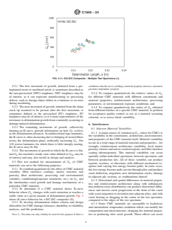
5.2 Conducting this test produces multiple values of GIc which are traditionally plotted against the delamination length at which that value was measured (see Fig. 2). The specific data of value to the test requestor will depend on the end use that motivated testing.
5.2.1 The first increment of growth, initiated from a pre-implanted insert or machined notch, is sometimes described as the non-precracked (NPC) toughness. NPC toughness may be of interest, as it can represent manufacturing or processing defects, such as foreign object debris in a laminate or an error during machining.
5.2.2 The next increment of growth, initiated from the sharp crack tip assumed to be present after the first increment, is sometimes defined as the precracked (PC) toughness. PC toughness may be of interest, as it is more representative of the resistance to delamination growth from a naturally occurring or damage-induced delamination.
5.2.3 The remaining increments of growth, collectively forming an R-curve, provide information on how GIc evolves as the delamination advances. In unidirectional tape laminates, the R-curve is often increasing due to bridging of nested fibers across the delamination plane, artificially increasing GIc. For 2-D woven laminates for which there is little interply nesting, the R-curve may be flat.
5.2.4 The increments of growth in which the R-curve is flat, and GIc has reached a steady state value defined as GIR, may be of interest and may also useful in design and analysis.
5.3 This test method for measurement of GIc of CMC materials can serve the fol...
SCOPE
1.1 This test method describes the experimental methods and procedures for the determination of the critical mode I interlaminar strain energy release rate of continuous fiber- reinforced ceramic matrix composite (CMC) materials in terms of GIc. This property is also sometimes described as the mode I fracture toughness or the mode I fracture resistance.
1.2 This test method applies primarily to ceramic matrix composite materials with a 2-D laminate structure, consisting of lay-ups of continuous ceramic fibers, in unidirectional tape or 2-D woven fabric architectures, within a brittle ceramic matrix.
1.3 This test method determines the elastic strain energy released per unit of new surface area created as a delamination grows at the interlaminar interface between two lamina or plies. The term delamination is used in this test method to specifically refer to this type of growth, while the term crack is a more general term that can also refer to matrix cracking, intralaminar delamination growth, or fiber fracture.
1.4 This test method uses a double cantilever beam (DCB) specimen to determine the critical mode I interlaminar strain energy release rate (GIc). A DCB test method has been standardized for polymer matrix composites (PMCs) under Test Method D5528. This test method addresses a similar procedure, but with modifications to account for the different physical properties, reinforcement architectures, stress-strain response, and failure mechanisms of CMCs compared to PMCs.
1.5 This test is written for ambient temperature and atmospheric test conditions, but the test method can also be used for elevated temperature or environmental exposure testing with the use of an appropriate environmental test chamber, measurement equipment for controlling and measuring the chamber temperature, humidity, and atmosphere, high temperature gripping fixtures, and modified equipment for measuring delamination growth.
1.6 The...
- Status
- Published
- Publication Date
- 31-Dec-2023
- Technical Committee
- C28 - Advanced Ceramics
- Drafting Committee
- C28.07 - Ceramic Matrix Composites
Overview
ASTM C1940-24 outlines the standard test method for measuring the critical Mode I interlaminar strain energy release rate (GIc) of continuous fiber-reinforced advanced ceramics at ambient temperatures. This standard is crucial in evaluating the Mode I fracture toughness, also known as the Mode I fracture resistance, of ceramic matrix composite (CMC) materials. With the growing usage of CMCs in critical engineering applications due to their high strength-to-weight ratio and thermal stability, assessing their resistance to interlaminar delamination is vital for material development, quality assurance, and structural design.
The method primarily applies to 2-D laminate CMCs with continuous ceramic fiber reinforcement, including those in unidirectional tape or 2-D woven fabric configurations. It uses the double cantilever beam (DCB) specimen as the basis for testing, ensuring measured fracture toughness values are relevant for actual engineering scenarios.
Key Topics
- Critical Mode I Strain Energy Release Rate (GIc): Measures the energy required for interlaminar delamination propagation, a key failure mode in laminated composites.
- Fracture Toughness Characterization: The test provides quantitative data for both the non-precracked (NPC) and precracked (PC) toughness, indicating how the material handles initial defects and crack propagation.
- R-Curve Behavior: The test tracks how GIc values change as delamination grows, providing insight into mechanisms such as fiber bridging or crack stabilization in various CMC architectures.
- Experimental Controls: Recommendations for specimen geometry, preparation, testing apparatus, and measurement methods ensure reproducibility and relevance of results.
- Environmental Versatility: While the standard addresses ambient testing, it also provides guidelines for elevated or reduced temperature, and humidity-controlled testing with appropriate equipment.
- Material and Specimen Considerations: Emphasizes controlling material variables such as fiber architecture, matrix characteristics, and specimen uniformity to ensure reliable, meaningful results.
Applications
- Material Development and Selection: Enables material scientists and engineers to evaluate and compare the delamination resistance of different CMC compositions and architectures, aiding in the selection and improvement of high-performance composites.
- Design of Structural Components: Provides key data for mechanical designers to assess damage tolerance, predict life expectancy, and implement failure criteria in CMC components, particularly in automotive, aerospace, and energy sectors.
- Quality Control & Lot Acceptance: Facilitates batch-to-batch performance comparison and helps set acceptance benchmarks to maintain consistent manufacturing quality.
- Failure Analysis: Offers insights into potential delamination-related failures by simulating and characterizing the progression of interlaminar cracks under Mode I loading conditions.
- Environmental Testing: The method can also be adapted to examine the effects of temperature, humidity, and environmental exposure on the interlaminar toughness of CMCs.
Related Standards
- ASTM D5528: Test Method for Mode I Interlaminar Fracture Toughness of Unidirectional Fiber-Reinforced Polymer Matrix Composites.
- ASTM C1145: Standard Terminology of Advanced Ceramics.
- ASTM C1275: Test Method for Monotonic Tensile Behavior of Continuous Fiber-Reinforced Advanced Ceramics.
- ASTM C1359: Test Method for Monotonic Tensile Strength Testing of Continuous Fiber-Reinforced Advanced Ceramics at Elevated Temperatures.
- ASTM D3878: Terminology for Composite Materials.
- ASTM E4: Practices for Force Calibration and Verification of Testing Machines.
- ASTM E561: Test Method for K Curve Determination.
- IEEE/ASTM SI 10: Metric Practice Standard.
These documents offer supporting terminology, testing, and calibration procedures integral to performing and understanding ASTM C1940-24, ensuring consistency and comparability across the field of advanced ceramics and composites.
Keywords: ASTM C1940-24, ceramic matrix composites, CMC, interlaminar strain energy release rate, Mode I fracture, GIc, double cantilever beam, fracture toughness, delamination, advanced ceramics, mechanical testing standards.
Relations
- Effective Date
- 15-Feb-2024
- Effective Date
- 01-Feb-2024
- Effective Date
- 01-Feb-2023
Frequently Asked Questions
ASTM C1940-24 is a standard published by ASTM International. Its full title is "Standard Test Method for Critical Mode I Interlaminar Strain Energy Release Rate of (<emph type="ital">G<inf>Ic</inf></emph>) Continuous Fiber-Reinforced Advanced Ceramics at Ambient Temperatures". This standard covers: SIGNIFICANCE AND USE 5.1 Interlaminar delamination growth can be a critical failure mode in laminated CMC structures. Knowledge of the resistance to interlaminar delamination growth of a laminated CMC is essential for material development and selection, and for CMC component design. (See (1-8)3 which give GIc values of 20 J/m2 to 800 J/m2 for different CMC and carbon-carbon composite systems at ambient temperatures.) 5.2 Conducting this test produces multiple values of GIc which are traditionally plotted against the delamination length at which that value was measured (see Fig. 2). The specific data of value to the test requestor will depend on the end use that motivated testing. 5.2.1 The first increment of growth, initiated from a pre-implanted insert or machined notch, is sometimes described as the non-precracked (NPC) toughness. NPC toughness may be of interest, as it can represent manufacturing or processing defects, such as foreign object debris in a laminate or an error during machining. 5.2.2 The next increment of growth, initiated from the sharp crack tip assumed to be present after the first increment, is sometimes defined as the precracked (PC) toughness. PC toughness may be of interest, as it is more representative of the resistance to delamination growth from a naturally occurring or damage-induced delamination. 5.2.3 The remaining increments of growth, collectively forming an R-curve, provide information on how GIc evolves as the delamination advances. In unidirectional tape laminates, the R-curve is often increasing due to bridging of nested fibers across the delamination plane, artificially increasing GIc. For 2-D woven laminates for which there is little interply nesting, the R-curve may be flat. 5.2.4 The increments of growth in which the R-curve is flat, and GIc has reached a steady state value defined as GIR, may be of interest and may also useful in design and analysis. 5.3 This test method for measurement of GIc of CMC materials can serve the fol... SCOPE 1.1 This test method describes the experimental methods and procedures for the determination of the critical mode I interlaminar strain energy release rate of continuous fiber- reinforced ceramic matrix composite (CMC) materials in terms of GIc. This property is also sometimes described as the mode I fracture toughness or the mode I fracture resistance. 1.2 This test method applies primarily to ceramic matrix composite materials with a 2-D laminate structure, consisting of lay-ups of continuous ceramic fibers, in unidirectional tape or 2-D woven fabric architectures, within a brittle ceramic matrix. 1.3 This test method determines the elastic strain energy released per unit of new surface area created as a delamination grows at the interlaminar interface between two lamina or plies. The term delamination is used in this test method to specifically refer to this type of growth, while the term crack is a more general term that can also refer to matrix cracking, intralaminar delamination growth, or fiber fracture. 1.4 This test method uses a double cantilever beam (DCB) specimen to determine the critical mode I interlaminar strain energy release rate (GIc). A DCB test method has been standardized for polymer matrix composites (PMCs) under Test Method D5528. This test method addresses a similar procedure, but with modifications to account for the different physical properties, reinforcement architectures, stress-strain response, and failure mechanisms of CMCs compared to PMCs. 1.5 This test is written for ambient temperature and atmospheric test conditions, but the test method can also be used for elevated temperature or environmental exposure testing with the use of an appropriate environmental test chamber, measurement equipment for controlling and measuring the chamber temperature, humidity, and atmosphere, high temperature gripping fixtures, and modified equipment for measuring delamination growth. 1.6 The...
SIGNIFICANCE AND USE 5.1 Interlaminar delamination growth can be a critical failure mode in laminated CMC structures. Knowledge of the resistance to interlaminar delamination growth of a laminated CMC is essential for material development and selection, and for CMC component design. (See (1-8)3 which give GIc values of 20 J/m2 to 800 J/m2 for different CMC and carbon-carbon composite systems at ambient temperatures.) 5.2 Conducting this test produces multiple values of GIc which are traditionally plotted against the delamination length at which that value was measured (see Fig. 2). The specific data of value to the test requestor will depend on the end use that motivated testing. 5.2.1 The first increment of growth, initiated from a pre-implanted insert or machined notch, is sometimes described as the non-precracked (NPC) toughness. NPC toughness may be of interest, as it can represent manufacturing or processing defects, such as foreign object debris in a laminate or an error during machining. 5.2.2 The next increment of growth, initiated from the sharp crack tip assumed to be present after the first increment, is sometimes defined as the precracked (PC) toughness. PC toughness may be of interest, as it is more representative of the resistance to delamination growth from a naturally occurring or damage-induced delamination. 5.2.3 The remaining increments of growth, collectively forming an R-curve, provide information on how GIc evolves as the delamination advances. In unidirectional tape laminates, the R-curve is often increasing due to bridging of nested fibers across the delamination plane, artificially increasing GIc. For 2-D woven laminates for which there is little interply nesting, the R-curve may be flat. 5.2.4 The increments of growth in which the R-curve is flat, and GIc has reached a steady state value defined as GIR, may be of interest and may also useful in design and analysis. 5.3 This test method for measurement of GIc of CMC materials can serve the fol... SCOPE 1.1 This test method describes the experimental methods and procedures for the determination of the critical mode I interlaminar strain energy release rate of continuous fiber- reinforced ceramic matrix composite (CMC) materials in terms of GIc. This property is also sometimes described as the mode I fracture toughness or the mode I fracture resistance. 1.2 This test method applies primarily to ceramic matrix composite materials with a 2-D laminate structure, consisting of lay-ups of continuous ceramic fibers, in unidirectional tape or 2-D woven fabric architectures, within a brittle ceramic matrix. 1.3 This test method determines the elastic strain energy released per unit of new surface area created as a delamination grows at the interlaminar interface between two lamina or plies. The term delamination is used in this test method to specifically refer to this type of growth, while the term crack is a more general term that can also refer to matrix cracking, intralaminar delamination growth, or fiber fracture. 1.4 This test method uses a double cantilever beam (DCB) specimen to determine the critical mode I interlaminar strain energy release rate (GIc). A DCB test method has been standardized for polymer matrix composites (PMCs) under Test Method D5528. This test method addresses a similar procedure, but with modifications to account for the different physical properties, reinforcement architectures, stress-strain response, and failure mechanisms of CMCs compared to PMCs. 1.5 This test is written for ambient temperature and atmospheric test conditions, but the test method can also be used for elevated temperature or environmental exposure testing with the use of an appropriate environmental test chamber, measurement equipment for controlling and measuring the chamber temperature, humidity, and atmosphere, high temperature gripping fixtures, and modified equipment for measuring delamination growth. 1.6 The...
ASTM C1940-24 has the following relationships with other standards: It is inter standard links to ASTM E1823-24a, ASTM E1823-24, ASTM E1823-23. Understanding these relationships helps ensure you are using the most current and applicable version of the standard.
ASTM C1940-24 is available in PDF format for immediate download after purchase. The document can be added to your cart and obtained through the secure checkout process. Digital delivery ensures instant access to the complete standard document.
Standards Content (Sample)
This international standard was developed in accordance with internationally recognized principles on standardization established in the Decision on Principles for the
Development of International Standards, Guides and Recommendations issued by the World Trade Organization Technical Barriers to Trade (TBT) Committee.
Designation: C1940 − 24
Standard Test Method for
Critical Mode I Interlaminar Strain Energy Release Rate of
(G ) Continuous Fiber-Reinforced Advanced Ceramics at
Ic
Ambient Temperatures
This standard is issued under the fixed designation C1940; the number immediately following the designation indicates the year of
original adoption or, in the case of revision, the year of last revision. A number in parentheses indicates the year of last reapproval. A
superscript epsilon (´) indicates an editorial change since the last revision or reapproval.
1. Scope ber temperature, humidity, and atmosphere, high temperature
gripping fixtures, and modified equipment for measuring de-
1.1 This test method describes the experimental methods
lamination growth.
and procedures for the determination of the critical mode I
1.6 The values stated in SI units are to be regarded as
interlaminar strain energy release rate of continuous fiber-
reinforced ceramic matrix composite (CMC) materials in terms standard. No other units of measurement are included in this
standard.
of G . This property is also sometimes described as the mode
Ic
I fracture toughness or the mode I fracture resistance. 1.6.1 Values expressed in this test method are in accordance
with the International System of Units (SI) and IEEE/ASTM SI
1.2 This test method applies primarily to ceramic matrix
10.
composite materials with a 2-D laminate structure, consisting
1.7 This standard does not purport to address all of the
of lay-ups of continuous ceramic fibers, in unidirectional tape
safety concerns, if any, associated with its use. It is the
or 2-D woven fabric architectures, within a brittle ceramic
responsibility of the user of this standard to establish appro-
matrix.
priate safety, health, and environmental practices and deter-
1.3 This test method determines the elastic strain energy
mine the applicability of regulatory limitations prior to use.
released per unit of new surface area created as a delamination
Specific hazard statements are given in Section 8.
grows at the interlaminar interface between two lamina or
1.8 This international standard was developed in accor-
plies. The term delamination is used in this test method to
dance with internationally recognized principles on standard-
specifically refer to this type of growth, while the term crack is
ization established in the Decision on Principles for the
a more general term that can also refer to matrix cracking,
Development of International Standards, Guides and Recom-
intralaminar delamination growth, or fiber fracture.
mendations issued by the World Trade Organization Technical
Barriers to Trade (TBT) Committee.
1.4 This test method uses a double cantilever beam (DCB)
specimen to determine the critical mode I interlaminar strain
2. Referenced Documents
energy release rate (G ). A DCB test method has been
Ic
standardized for polymer matrix composites (PMCs) under
2.1 ASTM Standards:
Test Method D5528. This test method addresses a similar
C1145 Terminology of Advanced Ceramics
procedure, but with modifications to account for the different
C1275 Test Method for Monotonic Tensile Behavior of
physical properties, reinforcement architectures, stress-strain
Continuous Fiber-Reinforced Advanced Ceramics with
response, and failure mechanisms of CMCs compared to
Solid Rectangular Cross-Section Test Specimens at Am-
PMCs.
bient Temperature
C1359 Test Method for Monotonic Tensile Strength Testing
1.5 This test is written for ambient temperature and atmo-
of Continuous Fiber-Reinforced Advanced Ceramics With
spheric test conditions, but the test method can also be used for
Solid Rectangular Cross Section Test Specimens at El-
elevated temperature or environmental exposure testing with
evated Temperatures
the use of an appropriate environmental test chamber, mea-
D2651 Guide for Preparation of Metal Surfaces for Adhesive
surement equipment for controlling and measuring the cham-
Bonding
D3878 Terminology for Composite Materials
This test method is under the jurisdiction of ASTM Committee C28 on
Advanced Ceramics and is the direct responsibility of Subcommittee C28.07 on For referenced ASTM standards, visit the ASTM website, www.astm.org, or
Ceramic Matrix Composites. contact ASTM Customer Service at service@astm.org. For Annual Book of ASTM
Current edition approved Jan. 1, 2024. Published January 2024. DOI: 10.1520/ Standards volume information, refer to the standard’s Document Summary page on
C1940-24. the ASTM website.
Copyright © ASTM International, 100 Barr Harbor Drive, PO Box C700, West Conshohocken, PA 19428-2959. United States
C1940 − 24
D5528 Test Method for Mode I Interlaminar Fracture Tough- 3.2.6 mode, adj—one of the three classes of crack (surface)
ness of Unidirectional Fiber-Reinforced Polymer Matrix displacements adjacent to the crack tip; these displacement
Composites modes are associated with the stress-strain fields around the
E4 Practices for Force Calibration and Verification of Test- crack tip and are designated one, two, and three; arabic
ing Machines numerals 1, 2, and 3 are used for the general case, and they
E6 Terminology Relating to Methods of Mechanical Testing represent opening, sliding, and tearing displacements, respec-
E83 Practice for Verification and Classification of Exten- tively (see Fig. 8 in Terminology E1823); roman numerals are
someter Systems used to specialize the mode to plane strain (I and II) or to
E105 Guide for Probability Sampling of Materials antiplane-strain (III). E1823
E122 Practice for Calculating Sample Size to Estimate, With
3.3 Definitions of Terms Specific to This Standard:
Specified Precision, the Average for a Characteristic of a
3.3.1 crack opening mode (Mode I), n—the fracture mode in
Lot or Process
which the crack faces open away from each other and no crack
E337 Test Method for Measuring Humidity with a Psy-
face shear movement occurs.
chrometer (the Measurement of Wet- and Dry-Bulb Tem-
3.3.2 critical mode I interlaminar strain energy release rate
peratures)
-2 -1
(G ), [FLL , FL ], n—the value of strain energy release rate
E561 Test Method for K Curve Determination Ic
R
-2 -1
(G) [FLL , FL ] for the onset of delamination growth as a
E691 Practice for Conducting an Interlaboratory Study to
result of an opening force or opening displacement.
Determine the Precision of a Test Method
3.3.2.1 Discussion—When the elastic strain energy (G)
E1402 Guide for Sampling Design
stored in the specimen reaches or exceeds a critical value (G ),
E1823 Terminology Relating to Fatigue and Fracture Testing
c
energy is dissipated by the creation of new surface area (crack
IEEE/ASTM SI 10 American National Standard for Metric
growth) until the stored energy is less than a critical value.
Practice
3.3.3 load point displacement (δ) [L], n—the force-induced
3. Terminology
separation vector between the two points of load application on
the cantilever arms.
3.1 The definitions of terms relating to mechanical testing
3.3.3.1 Discussion—For Mode I crack opening, the direc-
appearing in Terminology E6 apply to the terms used in this
tion of the separation vector is normal to the crack plane and
test method. The definitions of terms relating to fracture testing
parallel to the force vector.
appearing in Terminology E1823 apply to the terms used in this
test method. The definitions of terms relating to advanced
3.3.4 precrack, n—a starting delamination, artificially pro-
ceramics appearing in Terminology C1145 apply to the terms
duced from a pre-implanted insert or machined notch, from
used in this test method. The definitions of terms relating to
which subsequent delamination growth occurs.
fiber-reinforced composites appearing in Terminology D3878
3.3.5 resistance curve (R-curve), n—a plot of critical mode
apply to the terms used in this test method. Pertinent definitions
I interlaminar strain energy release rate (G ) versus delamina-
Ic
are shown in the following subsection, with the appropriate
tion length (a) for stable delamination advance.
source given in bold.
3.3.5.1 Discussion—If the material shows R-curve behavior,
3.2 Definitions:
G will be different at increasing delamination lengths com-
Ic
3.2.1 advanced ceramic, n—highly engineered, high
pared to the initial value. The changes can occur because the
performance, predominantly nonmetallic, inorganic, ceramic
fracture mechanisms change in mode or amplitude, or both,
material having specific functional attributes. C1145
during crack progression, absorbing more or less strain energy
with increasing delamination length. In unidirectional tape
3.2.2 ceramic matrix composite, n—material consisting of
two or more materials (insoluble in one another), in which the laminates, R-curve behavior is often caused by fiber bridging.
If there are no changes in energy absorption with delamination
major, continuous component (matrix component) is a ceramic,
while the secondary component(s) (reinforcing component) extension, the initiation G and the propagation G are
Ic Ic
may be ceramic, glass-ceramic, glass, metal or organic in equivalent and the material does not show R-curve behavior.
nature; these components are combined on a macroscale to
3.3.5.2 Discussion—If the propagation values of G reach a
Ic
form a useful engineering material possessing certain proper-
stable values, this is sometimes referred to as G in reference
IR
ties or behavior not possessed by the individual constituents.
to R-curve behavior.
C1145
3.3.6 strain energy release rate, G [FL-1], n—the loss of
3.2.3 continuous fiber-reinforced ceramic matrix composite
elastic strain energy, dU, in the test specimen per unit of
(CFCC), n—ceramic matrix composite in which the reinforc-
specimen width for an infinitesimal increase in length, da, of a
ing phase consists of a continuous fiber, continuous yarn, or a
delamination growing self-similarly under a constant displace-
woven fabric. C1145
ment. In mathematical form,
3.2.4 fracture toughness, n—a generic term for measures of
1 dU
G 5 2 (1)
resistance to crack extension. C1145
b da
3.2.5 interlaminar, adj—describing objects (for example,
where:
voids), events (for example, fracture), or fields (for example,
G = strain energy release rate,
stress) between the plies of a laminate. D3878
C1940 − 24
4.4 Tensile opening forces are applied to the cantilever
b = specimen width,
beam arms of the DCB specimen by means of loading blocks
U = elastic strain energy in the test specimen, and
or piano hinges attached to the two opposing cantilever arms.
a = delamination length.
The applied tensile forces (P) and the load point displacements
3.3.6.1 Discussion—The strain energy release rate is sub-
(δ) of the cantilever arms are recorded, and the resulting
scripted to identify the mode of load or displacement imparting
extension of the mid-plane delamination (a) is measured and
stain energy in the specimen: Mode I opening (G ), Mode II
I
recorded at defined intervals of crack growth corresponding to
sliding or in-plane shear (G ), or Mode III tearing or anti-plane
II
the applied forces and load point displacements.
shear (G ).
III
4.5 The G is calculated from the applied force (P), the load
Ic
point displacements (δ), and the delamination lengths (a)
4. Summary of Test Method
measured during the test using a modified beam theory
4.1 This test method measures the critical strain energy
calculation method (or by alternative methods given in Annex
release rate for mode I interlaminar delamination growth (G )
Ic
A3).
in continuous fiber-reinforced CMC.
4.6 Multiple data points are required for data reduction,
4.2 This test method applies primarily to CMC materials
which results in multiple calculations for G . An R-curve of
Ic
with a 2-D laminate structure, consisting of lay-ups of continu-
G versus delamination length (Fig. 2) is generated to charac-
Ic
ous ceramic fibers (in woven fabric and uniaxial tape architec-
terize G as the delamination grows and possibly reaches a
Ic
tures) within a brittle ceramic matrix.
steady-state G value.
IR
NOTE 1—Fracture mechanisms and crack propagation paths are often
spatially variable within a given CMC test specimen, particularly for
5. Significance and Use
laminates with woven fabric reinforcement. These spatial variations are
based on anisotropy and inhomogeneity in reinforcement architecture,
5.1 Interlaminar delamination growth can be a critical
heterogeneous flaw/pore distribution, anisotropic and heterogeneous
failure mode in laminated CMC structures. Knowledge of the
stress-strain response, and spatial variations in matrix properties. These
resistance to interlaminar delamination growth of a laminated
architectural, microstructural, and property variations make it difficult in
CMC is essential for material development and selection, and
some materials to control the crack propagation and interlaminar fracture
to produce a true material property, rather than a structure-dependent
for CMC component design. (See (1-8) which give G values
Ic
2 2
property.
of 20 J ⁄m to 800 J ⁄m for different CMC and carbon-carbon
NOTE 2—This test method can be used for ceramic composite materials
composite systems at ambient temperatures.)
with a non-laminar architecture (containing some 3-D reinforcement) with
the understanding that the fracture toughness values in a given plane are
5.2 Conducting this test produces multiple values of G
Ic
strongly affected by the reinforcement in the perpendicular (z) direction
which are traditionally plotted against the delamination length
and shall be considered as a structure-dependent property, rather than a
at which that value was measured (see Fig. 2). The specific data
material property.
of value to the test requestor will depend on the end use that
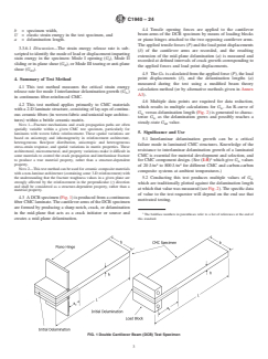
4.3 A DCB specimen (Fig. 1) is produced from a continuous
motivated testing.
fiber CMC laminate. The cantilever arms of the DCB specimen
are formed by producing a sharp notch, crack, or delamination
in the mid-plane that acts as a crack initiator or source and
The boldface numbers in parentheses refer to a list of references at the end of
creates a mid-plane delamination. this standard.
FIG. 1 Double Cantilever Beam (DCB) Test Specimen
C1940 − 24
FIG. 2 G SiC-SiC Composite - Multiple Test Specimens (1)
Ic
confidence that the test is yielding a material property and not a structural,
5.2.1 The first increment of growth, initiated from a pre-
geometry-dependent, property.
implanted insert or machined notch, is sometimes described as
the non-precracked (NPC) toughness. NPC toughness may be
5.3.4 To compare quantitatively the relative values of G
Ic
of interest, as it can represent manufacturing or processing
for different CMC materials with different constituents and
defects, such as foreign object debris in a laminate or an error
material properties, reinforcement architectures, processing
during machining.
parameters, or environmental exposure conditions; and
5.2.2 The next increment of growth, initiated from the sharp
5.3.5 To compare quantitatively the values of G obtained
Ic
crack tip assumed to be present after the first increment, is
from different batches of a specific CMC material, to perform
sometimes defined as the precracked (PC) toughness. PC
lot acceptance quality control, to use as a material screening
toughness may be of interest, as it is more representative of the
criterion, or to assess batch variability.
resistance to delamination growth from a naturally occurring or
damage-induced delamination.
6. Interferences
5.2.3 The remaining increments of growth, collectively
6.1 Inherent Material Variability:
forming an R-curve, provide information on how G evolves
Ic
6.1.1 A major source of variation in G values for CMCs is
Ic
as the delamination advances. In unidirectional tape laminates,
the variability in the constituents, architecture, microstructure,
the R-curve is often increasing due to bridging of nested fibers
and properties of the CMC material itself. Material variability
across the delamination plane, artificially increasing G . For
Ic
occurs in a wide range of material structure and properties – for
2-D woven laminates for which there is little interply nesting,
example, reinforcement architecture variability, local matrix
the R-curve may be flat.
porosity clusters and micro-cracked regions, and fiber interface
5.2.4 The increments of growth in which the R-curve is flat,
coating inhomogeneity. This material variability can occur
and G has reached a steady state value defined as G , may be
Ic IR
spatially within individual specimens, between specimens, and
of interest and may also useful in design and analysis.
between production lots. All of these variables can produce
5.3 This test method for measurement of G of CMC
Ic
regions, sections, or directions with different mechanical re-
materials can serve the following purposes:
sponse and varying low-energy fracture paths. In some cases,
5.3.1 To establish quantitatively the effect of CMC material
the low-energy fracture path can run through plies and produce
variables (fiber interface coatings, matrix structure and
crack deflection, migration, new delamination cracks, damage
porosity, fiber architecture, processing and environmental
in adjacent ply sections, or combinations thereof.
variables, conditioning/exposure treatments, etc.) on G and
Ic
6.1.2 Directional and spatial differences in material proper-
the interlaminar crack growth and damage mechanisms of a
ties and reinforcement architecture along with unbalanced,
particular CMC material;
non-uniform stress distributions can produce directional differ-
5.3.2 To determine if a CMC material shows R-curve
ences and uneven crack progression at the front of the crack
behavior where G changes with crack extension or reaches a
Ic
with crack migration or deviation into adjacent plies, and with
stable value at a given amount of delamination growth. Fig. 2
crack bowing or dragging in the center of the test specimen,
shows R-curve behavior for a SiC-SiC composite (1);
compared to the edges of the test specimen.
5.3.3 To develop delamination failure criteria and design
6.1.3 Some CMC materials are susceptible to hydrolysis
allowables for CMC damage tolerance, durability or reliability
and intermediate temperature oxidation which can modify the
analyses, and life prediction;
composition and microstructure, changing the material proper-
NOTE 3—Test data can only reliably be used for this purpose if there is ties or producing slow crack growth. These effects can occur
C1940 − 24
during unprotected storage, with specific conditioning 6.3.1 Specimen thickness (h) and cantilever arm thicknesses
treatments, or under environmental test conditions and slow (h and h – see Fig. 4) are key geometric variables determin-
1 2
strain (creep) conditions. ing the mechanical response of the cantilever arms. With thin
test specimens and thin cantilever arms, the cantilevers arms
6.2 Experimental Interferences:
can be over-strained and shift out of the elastic stress-strain
6.2.1 The calculation of G in this test method assumes
Ic
regime. With thick test specimens, cantilever arms that are too
linear elastic behavior in the cantilever arms. This assumption
thick may exhibit significant amounts of transverse shear
is valid when the cantilever arms are structurally rigid and
deformation, which is not accounted for in the data reduction
strong enough to deform elastically. Nonlinear deformation,
methods.
damage, and fracture in the cantilever arms invalidates the
6.3.2 The assumption that the specimen is under pure mode
assumption of linear elastic behavior.
I loading is predicated on the bending forces on the cantilever
6.2.2 The calculation of G in this test method assumes that
Ic
arms being balanced and equivalent. This requires that the
the delamination crack starts, extends, and remains in the
thickness of the two arms (h and h ) are equal and the
1 2
mid-plane of the test specimen, without deflection, migration,
delamination is located exactly at the mid-plane, but this may
or branching into and through adjacent plies with crack
be difficult to achieve with small, thin specimens.
extension. Crack deflection, branching, and multiple crack
formations are significant interferences for the test method.
NOTE 4—Analysis using Classical Beam Theory assumptions (1)
showed that if the thickness of the two cantilever arms are within 20 % of
6.2.3 The calculation of G in this test method assumes
Ic
each other (120 % ≥ h /h ≥ 80 %), the calculated value of G is
1 2 I
uniform delamination growth across the specimen width. The
overestimated by 5 % or less. However, overestimation is unconservative,
recommended method to determine delamination length is the
there is no estimate provided for the mode II component introduced due
visual observation method, although other methods (see Annex
to the asymmetry, and it is also not well known how mixed-mode
A4) exist. The visual observation method assumes that the conditions, with even small components of G , may effect G . It should
II c
therefore be endeavored to keep the cantilever arms as equal as possible.
delamination length, as measured at one specimen edge, is
representative of overall, uniform delamination growth. Non-
6.3.3 Calculation of G requires accurate measurement of
Ic
uniform delamination growth, which can produce curved,
the delamination tip position through the duration of the test. In
slanted, or wavy delamination fronts, invalidates this assump-
some CMCs it is very difficult to visually measure the
tion.
delamination tip position from the side of the specimen.
6.2.4 Delamination growth may initiate and progress in one
Techniques can be used to "highlight" the appearance of the
of two ways: (1) by a slow, stable crack extension/growth or
crack for accurate visual measurement, but identification can
(2) a run-arrest extension, in which the delamination front
still be difficult.
jumps ahead abruptly with a drop in applied force and then the
6.3.4 If G is to be accurately used as a conservative
Ic
crack extends further, only with a subsequent increase in
material property for design and analysis purposes, the speci-
applied force (Fig. 3). Slow, stable crack growth is of primary
men must be designed such that the linear-elastic fracture
interest in this test method, because rapid delamination growth
mechanics’ assumption of a small process zone size relative to
may introduce dynamic effects in the test specimen and
the specimen characteristic length holds true. One way to
changes in the fracture morphology. The run-arrest crack
accomplish this is to construct a DCB test specimen based on
growth may develop if the precrack is not sharp enough, or it
the geometry recommendations in this test method and with a
may be an implicit property of the material.
0° unidirectional tape architecture, as opposed to a multidirec-
6.2.5 Precise construction and alignment of the two loading
tional layup or a woven fabric laminate architecture.
blocks or piano hinges used for load introduction are important
7. Apparatus
to align and balance the two load application points. Misalign-
ment may introduce undesirable load components (that is,
7.1 Test Machine—The test machine applies and measures
mode II or mode III loading).
the force and the displacement on the test specimen in a
controlled manner. A test machine commonly consists of a test
6.3 Specimen Interferences:
frame, force transducers, and the actuator or drive mechanism
with load train components and gripping fixtures. A properly-
calibrated test machine shall be used that conforms to the
requirements of Practices E4 and can be operated in a
displacement control mode.
7.2 Gripping Devices—Gripping devices are used to trans-
mit the applied force to the fixtured test specimens and to keep
the specimen properly aligned in the load train. The testing
machine shall be equipped with appropriate specimen grips to
attach to and apply force to the force application fixtures that
are bonded or attached to the specimen.
7.2.1 The load train shall have suitable couplers, universal
joints, and alignment fixtures to adjust and maintain the linear
and angular alignment of the load train to prevent extraneous
FIG. 3 Stable Growth and Run-Arrest Growth bending or twisting stresses in the test specimen.
C1940 − 24
FIG. 4 Starting Notch or Delamination Geometry, Location, and Orientation in the DCB Test Specimen
7.3 Force Application Fixtures—Either piano hinges or load 7.5.3 The load point displacement may be measured by
blocks bonded or attached to the specimen act as fixtures for optical microscope or camera devices that directly measure the
application of force to the specimen by the test machine. load point displacement. Accuracy of such devices shall be at
least 61 % of the expected displacement.
7.4 Force Indicator—The force transducer shall be capable
of indicating the total force applied to the test specimen. This
7.6 In-Situ Delamination Length Measurement—The exten-
device shall be essentially free from inertia lag at the specified
sion of the delamination in the specimen mid-plane during
rate of testing and shall indicate the applied force with an
testing shall be measured to an accuracy of at least 60.5 mm.
accuracy of 61 % of the maximum expected force during the
The preferred method to measure delamination length during
test. The force transducer shall conform to the requirements of
the test is optically, although other methods may be used.
Practices E4.
7.6.1 Delamination length should be measured visually by a
7.5 Load Point Displacement Measurement—The load point traveling optical microscope that follows the delamination tip
displacement (δ) between the two points of force application as the crack extends. The travelling optical microscope, or
on the two cantilever arms shall be measured with an accuracy equivalent magnifying device, should have a magnification no
of at least 61 % of the total displacement expected during the greater than 70×. It should be positioned on one side of the test
test. There are three optional methods for measuring the load specimen to observe the delamination as it extends along one
edge of the specimen during the test.
point displacement:
7.5.1 The load point displacement may be estimated as the
7.6.1.1 A mirror may be used to determine visually any
test machine cross-head displacement, provided the compli-
difference in crack extension from one side of the specimen to
ance deformation in the load train with the specimen grips
the other side. Alternatively, a second traveling optical micro-
attached is less than 2 % of the load point displacement of the
scope may be used.
test specimen;
7.6.2 Other measurement methods, such as recording vision
7.5.2 The load point displacement may be indirectly mea-
systems, crack length gauges bonded to the specimen edges,
sured with calibrated extensometers or displacement transduc-
electrical resistance measurement, acoustic emission signal
ers (mechanical or optical) attached to the crack mouth of the
analysis, and digital image correlation measurements may be
DCB specimen;
used to monitor and measure the delamination extension,
7.5.2.1 The load point displacement is calculated from the
provided the accuracy meets the 60.5 mm requirement.
geometric relationship between the crack mouth opening
7.7 Specimen Dimension Measuring Devices—
displacement and the load point displacement, which is offset
Micrometers, calipers, and other devices used for measuring
from the crack mouth in the direction of the crack tip.
specimen dimensions (Fig. 1 and Fig. 4) shall be accurate and
7.5.2.2 The recommended extensometer/displacement
precise to measure to the required dimensional tolerance levels
gauge has a working range of not more than twice the
specified.
displacement expected during the test. Accuracy shall be
within 61 % of the expected displacement. When an 7.7.1 The specimen dimensions of width (b) and thickness
extensometer/displacement transducer is attached to the loaded (h) should be measured with micrometers with a flat anvil on
end of the test specimen to measure the crack opening mouth smooth, machined edges and surfaces. A suitable-sized diam-
displacement, the transducer is supported and counter- eter ball anvil should be used on irregular, through-thickness
weighted to prevent tipping of the free end of the test specimen surfaces. For typical specimen geometries, the width should be
out of the horizontal plane. With a properly supported measured with an instrument with an accuracy of at least
transducer, the specimen will have little tendency to rotate and 60.1 mm. The thickness should be measured with an instru-
should not introduce extraneous, unbalanced bending stresses. ment with an accuracy of at least 60.05 mm.
C1940 − 24
7.7.2 The cantilever arm thicknesses (h and h in Fig. 4) upon fracture. Plastic shields can be used to encircle the test
1 2
and notch thickness (t in Fig. 4) should be measured with an fixture and specimen, and to capture specimen fragments.
n
instrument capable of an accuracy of at least 60.05 mm. Containment and retention of these fragments for later fracto-
Calipers or optical image analysis may be suitable instruments. graphic reconstruction and analysis is highly recommended.
7.7.3 The initial notch length (a in Fig. 1 and Fig. 4) should
8.2 Exposed fibers at the edges of CMC test specimens
be measured to an accuracy of at least 60.5 mm with an
present a hazard due to the sharp, brittle nature of the ceramic
instrument with an accuracy of at least 60.2 mm. Calipers or
fiber. Individuals required to handle these materials shall be
optical image analysis may be suitable instruments.
well-informed of such conditions and the proper handling
7.8 Data Acquisition Requirements—Use either digital data
techniques.
acquisition systems or analog chart recorders for recording the
applied force (P) and load point displacement (δ) versus time.
9. Test Specimens
A digital record is recommended for ease of later data analysis.
9.1 Test specimens shall be selected and prepared from
Recording devices shall be accurate to within 60.1 % for the
representative CMC materials that meet the defined testing
entire testing system including the readout unit as specified in
objectives and material requirements. Guide E105 and Guide
Practices E4 and with a recommended minimum data acquisi-
E1402 provide guidance and direction on developing a sam-
tion rate of 10 Hz and recommended minimum response of
pling plan. The method of sampling shall be reported.
50 Hz.
9.2 Material Architecture—The fiber reinforcement archi-
7.9 Conditioning Chamber—If test materials and test speci-
tecture in the CMC test specimen should be structured to
mens are to be pre-test conditioned in a defined environment
prevent the interlaminar crack from branching or migrating
(temperature, humidity, and atmosphere), a temperature/vapor/
from the mid-plane into adjacent plies or interfaces.
atmosphere-controlled conditioning chamber is required that is
9.2.1 CMCs composed of tape plies should be unidirec-
capable of maintaining the required temperature to within
tional and consist of only 0° plies, because off-axis plies, such
63 °C and the required relative humidity/vapor level and
as those oriented at 90° or 45°, are particularly susceptible to
atmosphere to within 65 %. Chamber environmental condi-
crack migration through and into adjacent plies. Orientations
tions shall be monitored either on an automated continuous
other than unidirectional 0° may be used if it can be shown that
basis or on a manual basis at regular intervals during the
delamination growth is constrained to the mid-plane interlami-
conditioning treatment.
nar interface.
7.10 This test method covers testing under ambient tem-
9.2.2 CMCs composed of woven fabric plies are generally
peratures. However, if non-ambient temperature testing is
less susceptible to crack migration and may generally be
conducted, test chambers should meet the below requirements.
comprised of any orientation, as long as it can be shown that
7.11 Cryogenic Test Chamber—If test specimens are to be
delamination growth is constrained to the mid-plane interlami-
tested in a low-temperature environment, a temperature con-
nar interface.
trolled test chamber is required that is capable of maintaining
9.2.3 If orientations other than purely unidirectional are
the required temperature to within 63 °C. Test chamber
selected for the fiber reinforcement architecture, the two
environmental conditions shall be monitored either on an
cantilever arm sub-laminates should each be mid-plane sym-
automated continuous basis or on a manual basis at regular
metric to avoid the effects of anticlastic bending that may be
intervals during the test.
introduced during testing if the sub-laminates are asymmetric.
7.12 Environmental Test Chamber—If test specimens are to 9.2.4 This test method can be used for CMCs with a
be tested in an elevated temperature environment or with
non-laminar architecture containing some 3-D reinforcement,
controlled humidity or atmosphere, a temperature/vapor/ per Note 2, and with the understanding that an interlaminar
atmosphere-controlled test chamber is required that is capable
interface, and thus an interlaminar strain energy release rate,
of maintaining the required temperature to within 63 °C and does not exist as conventionally defined.
the required relative humidity/vapor level and atmosphere to
9.2.5 If the initial delamination will be created using the
within 65 %. Test chamber environmental conditions shall be
insertion method (see 9.4.3.3), the laminate must contain an
monitored either on an automated continuous basis or on a
even number of plies. If the initial delamination will be created
manual basis at regular intervals during the test. See Annex A5
using the machining method, an even number of plies is
for more detail.
recommended, but is not required.
7.13 Safety and containment shields should be placed
9.3 Specimen Geometry and Dimensions—The rectangular
around the specimen and test fixture to contain and collect
test specimens have a recommended length (L) of at least
fracture fragments.
125 mm and a nominal width (b) from 20 mm to 25 mm
inclusive (Fig. 1). The test specimen architecture should be
8. Hazards
selected to produce a specimen thickness (h) between 3 mm
and 5 mm.
8.1 During the conduct of this test, there is a possibility of
flying fragments of broken test specimens. The brittle nature of 9.3.1 When testing woven fabric laminate composites, it is
advanced ceramics and the release of elastic strain energy recommended that the specimen width (b) be equal to two or
contribute to the potential release of uncontrolled fragments more weave unit cells.
C1940 − 24
9.3.2 The test specimens shall have a starting notch, less than 15 % of the specimen thickness (h). The tip of the
precrack, or delamination positioned in the x-y center plane of machined notch should be rounded or tapered, rather than
the specimen The initial length (a ) of the delamination is square. Final machining into a sharp notch should be per-
measured from the load point line to the tip of the delamination formed by hand-cutting in the notch root with a razor blade and
(Fig. 1 and Fig. 4). The delamination should have an initial an abrasive paste. This sharpening method is strongly recom-
length (a ) that produces a ratio of initial length to specimen mended for notches that develop a square root;
thickness (a /h) of at least 5 but preferably 10. This ratio keeps
9.4.3.2 Introduce a very thin, long, sharp precrack at the
the cantilever arms from being too thick or too thin. For test mid-plane of the test specimen by “wedging in” a thin knife
specimens 3 mm to 5 mm thick and 125 mm long, the
edge or razor blade in the center plane. Annex A1 describes a
recommended starting delamination length (a ) is 25 mm wedge method for introducing a sharp, straight, centered
(~20 % of the specimen length).
precrack; or
9.3.3 Alternative specimen lengths (L), specimen widths 9.4.3.3 Place a non-reactive film or foil insert at the mid-
(b), specimen thicknesses (h), and initial delamination lengths plane of the composite during fabrication to produce a con-
(a ) may be chosen that are consistent with preventing large trolled delamination of known length. The film or foil insert
cantilever arm deflections and reducing loading block geom- should be as thin as possible.
etry effects for low-modulus and high-strength materials.
NOTE 6—Non-reactive polymer film inserts on the order of 13 μm can
Annex A2 provides directions on determining the specimen
be used.
geometry dimensions for controlling large deflections and
(1) Graphite foil can be used as a high-temperature insert,
loading block geometry effects.
if the graphite will be non-reactive for the given CMC
fabrication conditions. Graphite foil can be used for chemical
NOTE 5—Shorter (~50 mm) SiC-SiC CMC specimens have been
vapor deposition and preceramic polymer processing
successfully tested within the requirements that the cantilever arm
thicknesses and the initial crack length meet the lever arm deflection fabrication, but not for air sintered oxide-oxide composites or
guidelines (9.3 and Annex A2), and that the loading blocks can be
non-oxide composites that use silicon melt infiltration.
successfully attached. Narrower (12 mm) and wider (37 mm) SiC-SiC test
(2) Organic films such as polytetrafluoroethylene (PTFE),
specimens have also been tested successfully. However, specimens with
polyethylene terephthalate (PET), or others can be used as an
geometry deviations from the recommendations should still be evaluated
insert during fabrication of many oxide-oxide composites.
for appropriateness depending on the use of the data collected. In
particular, very small specimens should be evaluated to confirm the
9.4.4 Force Application Fixture Bonding—Either loading
cracked arm aspect ratios (a /h) are sufficient to represent a beam in
blocks or piano hinges shall be used as force application
bending.
fixtures (see Fig. 1). In either instance, the force application
9.4 Specimen Preparation—Test specimens shall be cut in a
fixture shall be securely bonded or attached to the cantilever
manner to produce uniform widths within the specified toler-
arms of the test specimen. The force application fixtures should
ance and to minimize edge damage. Some machining options
be at least as wide as the specimen, with enough surface area
include waterjet, polycrystalline diamond (PCD) saw cutting,
for secure attachment to the specimen. It may be permissible to
PCD milling, and, for conductive CMCs, wire electrical
have force application fixtures that are slightly wider than the
discharge machining (EDM).
specimen. The force application fixtures shall be designed and
9.4.1 As-fabricated CMC surface roughness can be signifi-
constructed to sustain the maximum applied force, to minimize
cant and may make it difficult to subsequently cut and align the
the applied moment arm, and to reduce stiffening of the
starting notch or delamination in the center plane or securely
specimen cantilever arms.
bond the loading blocks or piano hinges to the specimen
NOTE 7—The applied moment arm is minimized by minimizing the
surface. If these issues are substantial enough to cause possible
vertical distance between the mid-plane of each cantilever arm and the
uneven loading or cantilever arm thickness variation greater
load point on the force application fixture (t in Fig. 5).
than 10 %, the specimen faces may be ground to remove the
NOTE 8—Stiffening of the specimen cantilever arm is minimized by
roughness.
minimizing the width of the force application fixture between the load
point and the delamination tip (L’ in Fig. 5).
9.4.2 The starting notch or delamination shall be located at
the mid-plane, centered through the thickness of test specimen
9.4.4.1 Loading Blocks—Loading blocks are solid, rectan-
across the width and along the full length of the crack to
gular blocks with horizontal holes for pin or cable attachment.
produce cantilever lever arms with uniform and approximately
A pair of loading blocks are bonded/attached to the two
equal thicknesses. h and h should be within 10 % of each
Fig. 1. The
1 2 cantilever ends of each specimen as shown in
other.
loading blocks shall be made of material capable of sustaining
9.4.3 Starting Notch or Delamination Production the applied force without incurring damage or fracture.
Method—A starting notch or delamination is generally pro-
9.4.4.2 Piano Hinges—Piano hinges are hinged tabs with
duced by one of three methods:
pivoting grip tabs. A pair of piano hinge tabs are bonded/
9.4.3.1 Use a diamond blade or diamond wire saw with a attached to the two cantilever ends of each specimen as shown
rounded or angled edge to machine a deep notch of the desired in Fig. 1. Hinges are commonly made of metal and have a pin
length through the mid-plane of the test specimen. The notch hinge that maintains alignment of the applied force without
should be produced with the smallest notch thickness (t ) introducing bending stresses. The hinge tabs shall be made of
n
possible; notch thicknesses of 0.5 mm or less are strongly a material capable of sustaining the applied force without
recommended. As a guideline, the notch thickness should be incurring damage or fracture.
C1940 − 24
FIG. 5 Definition of t and L’ for calculation of F and N (Eq 3 and 4)
9.4.4.3 The bonding surfaces of the force application fix- specimen internal morphology such as delamination shape and
tures and the specimen shall be properly cleaned before position, porosity concentrations, or architecture variability.
bonding to ensure load transfer without debonding of the Describe the method and the observations, results, or measure-
fixtures from the specimen during the test. The bonding surface ments of any nondestructive evaluations and include them in
of the specimen and the fixtures may be lightly grit-blasted or the final report.
scrubbed with sandpaper, then wiped clean with a volatile
9.6 Specimen Identification—Specimens should be marked
solvent, such as acetone or methylethylketone (MEK), to
with identification codes to maintain specimen identity and
remove any contamination. If this procedure results in a bond
traceability. Any markings should avoid surface damage to the
failure between the specimen and the fixtures during testing, it
stressed regions of the test specimens.
may be necessary to apply a more sophisticated cleaning
9.7 Storage of Specimens—Exercise care in handling,
procedure based on degreasing and chemical etching. Consult
packaging, and storage of test specimens to avoid the intro-
Guide D2651 for the surface preparation procedure that is most
duction of surface or volume damage. In addition, test speci-
appropriate for the particular material used for the force
mens may be stored in controlled environments or desiccators
application fixtures.
to avoid environmental (for example, humidity) degradation
9.4.4.4 Bonding of the force application fixtures to the
prior to testing.
specimen shall be performed immediately after surface prepa-
ration. The material recommended for bonding is a high- 9.8 Specimen Count—Test at least five (5) specimens per
strength, room-temperature cure adhesive such as a rapid
test condition for the purposes of estimating a mean value of
setting epoxy. However, in some cases, a superglue, such as G . If any tests are invalid, test an additional specimen for
Ic
cyanoacrylate, may provide sufficient bond strength. The
each invalid test. A greater number of test specimens may be
adhesive may benefit from post-cure if the specimens are dried necessary if estimates regarding the form of the G distribution
Ic
after the fixtures are mounted.
are required. If material cost or test specimen availability limits
the number of possible tests, fewer tests may be conducted to
NOTE 9—High temperature ceramic adhesives and precision screw and
determine an indication of material properties. For statistically
grip attachments are suitable for elevated temperature testing, and are
significant data, the procedures described in Practice E122
discussed further in Annex A
...