


ASTM G50-10(2015)
(Practice)Standard Practice for Conducting Atmospheric Corrosion Tests on Metals
Standard Practice for Conducting Atmospheric Corrosion Tests on Metals
SIGNIFICANCE AND USE
3.1 The procedures described herein can be used to evaluate the corrosion resistance of metals when exposed to the weather, as well as to evaluate the relative corrosivity of the atmosphere at specific locations. Because of the variability and complexity of weather effects and the industrial and natural factors influencing the atmospheric corrosivity of a test site, a multi-year exposure period should be considered to minimize their influence. Also, as corrosivity may vary at a site from season to season, exposures should be made either at the same time of the year to minimize variability or these differences should be established by multiple exposures.
3.2 Control specimens should always be employed in weathering tests. The control specimens should be from a material having established weathering characteristics. A substantial amount of corrosion data shall have been accumulated for the control specimens. It is also good practice to retain samples of all materials exposed so that possible effects of long-term aging can be measured.
SCOPE
1.1 This practice covers and defines conditions for exposure of metals and alloys to the weather. It sets forth the general procedures that should be followed in any atmospheric test. It is presented as an aid in conducting atmospheric corrosion tests so that some of the pitfalls of such testing may be avoided. As such, it is concerned mainly with panel exposures to obtain data for comparison purposes.
1.2 The values stated in inch-pound units are to be regarded as standard. The values given in parentheses are mathematical conversions to SI units that are provided for information only and are not considered standard.
1.3 This standard does not purport to address all of the safety concerns, if any, associated with its use. It is the responsibility of whoever uses this standard to consult and establish appropriate safety and health practices and determine the applicability of regulatory limitations prior to use.
General Information
Buy Standard
Standards Content (Sample)
NOTICE: This standard has either been superseded and replaced by a new version or withdrawn.
Contact ASTM International (www.astm.org) for the latest information
Designation: G50 − 10 (Reapproved 2015)
Standard Practice for
Conducting Atmospheric Corrosion Tests on Metals
This standard is issued under the fixed designation G50; the number immediately following the designation indicates the year of original
adoption or, in the case of revision, the year of last revision.Anumber in parentheses indicates the year of last reapproval.Asuperscript
epsilon (´) indicates an editorial change since the last revision or reapproval.
1. Scope G91 Practice for Monitoring Atmospheric SO Deposition
Rate for Atmospheric Corrosivity Evaluation
1.1 This practice covers and defines conditions for exposure
G92 Practice for Characterization of Atmospheric Test Sites
of metals and alloys to the weather. It sets forth the general
G140 Test Method for Determining Atmospheric Chloride
procedures that should be followed in any atmospheric test. It
Deposition Rate by Wet Candle Method
ispresentedasanaidinconductingatmosphericcorrosiontests
so that some of the pitfalls of such testing may be avoided.As
3. Significance and Use
such, it is concerned mainly with panel exposures to obtain
3.1 The procedures described herein can be used to evaluate
data for comparison purposes.
thecorrosionresistanceofmetalswhenexposedtotheweather,
1.2 The values stated in inch-pound units are to be regarded
as well as to evaluate the relative corrosivity of the atmosphere
as standard. The values given in parentheses are mathematical
at specific locations. Because of the variability and complexity
conversions to SI units that are provided for information only
of weather effects and the industrial and natural factors
and are not considered standard.
influencing the atmospheric corrosivity of a test site, a multi-
1.3 This standard does not purport to address all of the
year exposure period should be considered to minimize their
safety concerns, if any, associated with its use. It is the
influence.Also, as corrosivity may vary at a site from season to
responsibility of whoever uses this standard to consult and
season, exposures should be made either at the same time of
establish appropriate safety and health practices and deter-
the year to minimize variability or these differences should be
mine the applicability of regulatory limitations prior to use.
established by multiple exposures.
3.2 Control specimens should always be employed in
2. Referenced Documents
weathering tests. The control specimens should be from a
2.1 ASTM Standards:
material having established weathering characteristics. A sub-
A380 Practice for Cleaning, Descaling, and Passivation of
stantial amount of corrosion data shall have been accumulated
Stainless Steel Parts, Equipment, and Systems
for the control specimens. It is also good practice to retain
D2010/D2010M Test Methods for Evaluation of Total Sul-
samples of all materials exposed so that possible effects of
fation Activity in the Atmosphere by the Lead Dioxide
long-term aging can be measured.
Technique
G1 Practice for Preparing, Cleaning, and Evaluating Corro-
4. Test Sites
sion Test Specimens
4.1 Test sites should be chosen at a number of locations
G33 Practice for Recording Data from Atmospheric Corro-
representative of the atmospheric environments where the
sion Tests of Metallic-Coated Steel Specimens
metals or alloys are likely to be used. If such information is not
G46 Guide for Examination and Evaluation of Pitting Cor-
available, the selection should include sites typical of
rosion
industrial, rural, and marine atmospheres. Test site
G84 Practice for Measurement of Time-of-Wetness on Sur-
characterization, if needed, shall be conducted in accordance
faces Exposed to Wetting Conditions as in Atmospheric
with Practice G92.
Corrosion Testing
4.2 Exposure racks should be located in cleared, well-
drained areas such that the exposed specimens will be sub-
This practice is under the jurisdiction of ASTM Committee G01 on Corrosion
jected to the full effects of the atmosphere at the location of the
of Metals and is the direct responsibility of Subcommittee G01.04 on Atmospheric
Corrosion.
test site. Shadows of trees, buildings, or structures should not
Current edition approved Nov. 1, 2015. Published December 2015. Originally
fall on the specimens, and local contamination of the atmo-
approved in 1976. Last previous edition approved in 2010 as G50–10. DOI:
sphereshouldbeavoided,unlessthespecificinfluencesofsuch
10.1520/G0050-10R15.
For referenced ASTM standards, visit the ASTM website, www.astm.org, or conditions are intended to be assessed.
contact ASTM Customer Service at service@astm.org. For Annual Book of ASTM
4.3 In special cases, the exposure racks may be partially
Standards volume information, refer to the standard’s Document Summary page on
the ASTM website. shelteredtoallowaccumulationofcorrosivematerialsfromthe
Copyright © ASTM International, 100 Barr Harbor Drive, PO Box C700, West Conshohocken, PA 19428-2959. United States
G50 − 10 (2015)
air but at the same time prevent washing by rain. If sheltering 5.6 As most published data on atmospheric corrosion of
is used, its purpose and configuration should be described in metals are based on an exposure angle of 30° from the
detail. horizontal, facing south, it is recommended that this angle be
used. Racks should be designed so that the lowest specimens
4.4 If local pollution effects are to be investigated, the
are at least 30 in. (760 mm) above the ground. See Notes 2 and
samples should be exposed at different distances from the
3.
source and at different elevations. Where it is particularly
NOTE 2—Maximum exposure to the sun may be obtained by exposing
important to obtain corrosion rates involving a micro-
specimens facing south (for the northern hemisphere) at an angle equal to
environment, samples should be mounted directly on the
the latitude of the test site. Exposure at this angle will yield the lowest
structure involved. Suitable attachment must be devised for
corrosion rates for most materials. Although these corrosion rates will
each case.
change at other angles of exposure, the order of merit established for each
material will be the same.
NOTE 3—In special instances, it may be desirable to orient racks and
5. Exposure Racks and Frames
frames in the direction of a specific corrodent source, for example, the
5.1 Test racks and frames should be constructed of a
ocean, for marine environments. Also, this practice should not be
construed as prohibiting special orientation of test frames for specific test
material that will remain intact for the entire proposed period
purposes, but it is strongly suggested that in such cases testing also be
of exposure. Galvanized pipe has been found adequate for rack
done in accordance with this practice so that a basis point for comparison
constructioninmostenvironments(Note1).Type304stainless
with available data is determined. Any special orientation or preferential
steel is adequate as a frame material for all environments. For
source of corrosion should be specifically identified in the exposure site
marine exposures, alloy 400 UNS No. N04400 or Type 316 description.
stainless steel has also been successfully used. Aluminum
5.7 ArackofthedesignanddimensionsshowninFig.2will
(5052 and 6061-T6) and copper frames also have given
give the correct exposure angle and can support the specimen
satisfactory service in a wide range of environments. Care
frame described in 5.4.
should be observed in the use of copper frames, as corrosion
5.8 The ground under the racks should be kept free of
products splashed during rainfall might affect the corrosion of
weeds, bushes, and debris. Organic herbicides, defoliants, or
other metals such as aluminum or magnesium.
pesticides should not be used for this purpose.
NOTE 1—If galvanized pipe is field-threaded, thread areas must be
protected to ensure joint integrity for long exposure periods. In severe
6. Test Specimens
environments, additional coatings may be required to provide corrosion-
6.1 When the material to be tested is in sheet form, a
free service.
specimen size of 4 by 6 in. (100 by 150 mm) is appropriate.
5.2 Racks and frames also may be constructed of wood.
Specimens may be larger, for example, 4 by 8 in. (100 by 200
Insulators may be attached to wooden frames with aluminum
mm), to suit a particular test; however, the specimens prefer-
bronze, alloy 400, or stainless steel screws. In such a case, no
ably should not be smaller than 4 by 6 in.
wood sections should be used with dimensions less than 2 by
6.2 Toassureadequaterigidityofthespecimensontherack,
4 in. (50 by 100 mm), and at least two coats of an exterior
a minimum thickness of 0.030 in. (0.75 mm) is suggested. It
grade paint or enamel over a suitable primer must be applied.
may be difficult to accommodate thicknesses greater than
Periodic maintenance will be required on all wood construc-
0.250 in. (6.25 mm) in the insulator grooves. (Special deep-
tion.
throated insulators can be obtained to accommodate thicker
5.3 Solid, glazed, electrical insulator knobs should be used
specimens, or the edges of thicker specimens can be machined
to hold the specimens on the frames, using stainless steel, alloy
to fit standard insulators.)
400, aluminum, nylon, or bronze bolts and nuts. Specimens
6.3 When it is desired to test samples of odd shapes, such as
shallbemountedinthegroovesoftheseinsulators.Inselecting
bolts, nuts, pipes, angles, assemblies, and structures, etc., a
fasteners for use on specific frame materials, care should be
means of supporting them in the test racks must be devised. It
taken to avoid unfavorable galvanic relationships.
is important that the specimens be electrically insulated from
5.4 Asuitable frame for mounting the insulators is shown in
their respective supports and from each other to prevent
Fig. 1. This frame will accommodate 70 standard 4 by 6-in.
unintentional galvanic corrosion. However, if desired, galvanic
(100 by 150-mm) specimens; other sizes can be mounted by
couples of dissimilar metals can be exposed on these frames.
rearrangingtheinsulatorsintheholesprovided.Itisacceptable
Efforts should be made to minimize crevices between speci-
to slot the holes in the frames in such a manner that the
mens and support materials.
mounting frames are adjustable for specimens of other sizes.
6.4 The total number of test specimens required should be
This is a convenience when it is not possible to prepare
determinedfromaknowledgeofthedurationofthetestandthe
specimens of a preplanned size, and it is often helpful in fitting
planned removals of the specimens for intermediate evalua-
the specimens snugly into the frames.
tions. Usually it should not be necessary to remove specimens
5.5 The racks should be designed to give exposure to as prior to completing one year’s exposure, unless specific data
large an area of the underside of the specimens as possible. are required for corrosion occurring during earlier stages of
Structural members of the rack should not be located directly exposure. For reliable results, sufficient specimens should be
under the specimens where they would shelter the underside of used for multiple removals at each exposure period. Triplicate
the specimens. specimens for each examination period will usually satisfy this
G50 − 10 (2015)
FIG. 1 Suitable Test Frame
requirement. A suggested suitable removal schedule is 1, 2, 4, method is to attach a stainless steel tag by means of an
8, and 16 years. Removal schedules for tests of different insulated cord and a suitably located hole. Numbers stamped
periods of total exposure should be adjusted accordingly. on the back of the specimen and further protected by covering
with a good grade of electrical tape is a suitable technique for
6.5 Included with each series of test specimens should be an
short-term exposure tests. For materials that do not exhibit
appropriate number of control specimens, as defined in 3.2.
significant atmospheric corrosion (copper, aluminum, stainless
steels, etc.), it is sufficient to stamp the identification on the
7. Preparation of Test Specimens
face of the panel.
7.1 Specimens should be identified in a manner that will
endure for the life of the test. A good method is the use of a 7.2 Oil, grease, and dirt should be removed by degreasing
series of edge notches or drilled holes in the body of the with a solvent cleaner or scrubbing, or both, to remove
specimen arranged according to some desired code. Another insoluble soils (see Practice G1).Any mill scale or rust should
G50 − 10 (2015)
NOTE 1—Items 1, 2, 3, 4, 5, and 8 are 1 ⁄4-in. (31.8-mm) hot-dip galvanized pipe.
NOTE 2—Fill all legs with concrete to about 6 in. (152 mm) above ground line.
Metric Equivalents
ft-in. m ft-in. m Req. Item Name
0-0 0.254 3-7 1.092 12 10 Plugs
1-7 0.483 5-5 ⁄8 1.654 8 9 4-way fittings
1-10 ⁄4 0.565 6-1 1.854 26 8 Tees
1 3
1-10.5 0.572 6-6 ⁄8 1.984 4 5 Joining braces 28 ⁄4 in. L
2-2 0.660 9-0 2.743 7 4 Cross braces 22 ⁄4 in. L
3 1 1
2-4 ⁄4 0.730 11-9 ⁄2 3.594 10 3 Stringers 11 ft –9 ⁄2 in. L
2-6 0.762 12-2 3.708 6 2 Front legs 5 ft – 5 ⁄8 in. L
3-0 0.914 60-10 18.542 6 1 Back legs 6 ft – 6 ⁄8 in. L
FIG. 2 Suitable Test Rack Support
be removed from all ferrous specimens unless it is specifically 8. Procedure
desired to perform the test with the mill scale intact. Pickling
8.1 Mount the specimens on the racks so that they are
with inhibited acid as well as blasting with sand or grit are
supported by the insulators and do not make electrical contact
acceptable descaling methods. If acid pickling is used, care
with each other or with the supporting racks.
must be taken to stop the pickling action as soon as the mill
8.2 Atmospheric factors such as time of wetness of the
scale and rust have been removed. Stainless steels should be
specimens, temperature of the specimens, and the concentra-
pickled in accordance with Practice A380 to ensure surfaces
tion of atmospheric contaminants such as sulfur dioxide and
free of iron contamination.
chloridesinthelocalenvironmenthaveagreatinfluenceonthe
7.3 Specimens should be weighed to at least the nearest
corrosion rate of many metals, particularly in the early stages
0.01 g before exposure. More corrosion-resistant materials are
of exposure. Therefore, if possible, expose the test materials in
frequently weighed to the nearest 0.1 mg. When deemed
an environment similar to that to which they will be subjected
appropriate, the specimens should be photographed to take into
in actual use. Measurement of sulfate levels shall be made in
account pre-exposure surface defects. Records should be kept
accordance with Practice G91. Measurement of chloride leve
...
This document is not an ASTM standard and is intended only to provide the user of an ASTM standard an indication of what changes have been made to the previous version. Because
it may not be technically possible to adequately depict all changes accurately, ASTM recommends that users consult prior editions as appropriate. In all cases only the current version
of the standard as published by ASTM is to be considered the official document.
Designation: G50 − 10 G50 − 10 (Reapproved 2015)
Standard Practice for
Conducting Atmospheric Corrosion Tests on Metals
This standard is issued under the fixed designation G50; the number immediately following the designation indicates the year of original
adoption or, in the case of revision, the year of last revision. A number in parentheses indicates the year of last reapproval. A superscript
epsilon (´) indicates an editorial change since the last revision or reapproval.
1. Scope*Scope
1.1 This practice covers and defines conditions for exposure of metals and alloys to the weather. It sets forth the general
procedures that should be followed in any atmospheric test. It is presented as an aid in conducting atmospheric corrosion tests so
that some of the pitfalls of such testing may be avoided. As such, it is concerned mainly with panel exposures to obtain data for
comparison purposes.
1.2 The values stated in inch-pound units are to be regarded as standard. The values given in parentheses are mathematical
conversions to SI units that are provided for information only and are not considered standard.
1.3 This standard does not purport to address all of the safety concerns, if any, associated with its use. It is the responsibility
of whoever uses this standard to consult and establish appropriate safety and health practices and determine the applicability of
regulatory limitations prior to use.
2. Referenced Documents
2.1 ASTM Standards:
A380 Practice for Cleaning, Descaling, and Passivation of Stainless Steel Parts, Equipment, and Systems
D2010/D2010M Test Methods for Evaluation of Total Sulfation Activity in the Atmosphere by the Lead Dioxide Technique
G1 Practice for Preparing, Cleaning, and Evaluating Corrosion Test Specimens
G33 Practice for Recording Data from Atmospheric Corrosion Tests of Metallic-Coated Steel Specimens
G46 Guide for Examination and Evaluation of Pitting Corrosion
G84 Practice for Measurement of Time-of-Wetness on Surfaces Exposed to Wetting Conditions as in Atmospheric Corrosion
Testing
G91 Practice for Monitoring Atmospheric SO Deposition Rate for Atmospheric Corrosivity Evaluation
G92 Practice for Characterization of Atmospheric Test Sites
G140 Test Method for Determining Atmospheric Chloride Deposition Rate by Wet Candle Method
3. Significance and Use
3.1 The procedures described herein can be used to evaluate the corrosion resistance of metals when exposed to the weather,
as well as to evaluate the relative corrosivity of the atmosphere at specific locations. Because of the variability and complexity of
weather effects and the industrial and natural factors influencing the atmospheric corrosivity of a test site, a multi-year exposure
period should be considered to minimize their influence. Also, as corrosivity may vary at a site from season to season, exposures
should be made either at the same time of the year to minimize variability or these differences should be established by multiple
exposures.
3.2 Control specimens should always be employed in weathering tests. The control specimens should be from a material having
established weathering characteristics. A substantial amount of corrosion data shall have been accumulated for the control
specimens. It is also good practice to retain samples of all materials exposed so that possible effects of long-term aging can be
measured.
This practice is under the jurisdiction of ASTM Committee G01 on Corrosion of Metals and is the direct responsibility of Subcommittee G01.04 on Atmospheric
Corrosion.
Current edition approved Sept. 1, 2010Nov. 1, 2015. Published October 2010December 2015. Originally approved in 1976. Last previous edition approved in 20032010
as G50–76(2003).G50–10. DOI: 10.1520/G0050-10.10.1520/G0050-10R15.
For referenced ASTM standards, visit the ASTM website, www.astm.org, or contact ASTM Customer Service at service@astm.org. For Annual Book of ASTM Standards
volume information, refer to the standard’s Document Summary page on the ASTM website.
*A Summary of Changes section appears at the end of this standard
Copyright © ASTM International, 100 Barr Harbor Drive, PO Box C700, West Conshohocken, PA 19428-2959. United States
G50 − 10 (2015)
4. Test Sites
4.1 Test sites should be chosen at a number of locations representative of the atmospheric environments where the metals or
alloys are likely to be used. If such information is not available, the selection should include sites typical of industrial, rural, and
marine atmospheres. Test site characterization, if needed, shall be conducted in accordance with Practice G92.
4.2 Exposure racks should be located in cleared, well-drained areas such that the exposed specimens will be subjected to the
full effects of the atmosphere at the location of the test site. Shadows of trees, buildings, or structures should not fall on the
specimens, and local contamination of the atmosphere should be avoided, unless the specific influences of such conditions are
intended to be assessed.
4.3 In special cases, the exposure racks may be partially sheltered to allow accumulation of corrosive materials from the air but
at the same time prevent washing by rain. If sheltering is used, its purpose and configuration should be described in detail.
4.4 If local pollution effects are to be investigated, the samples should be exposed at different distances from the source and at
different elevations. Where it is particularly important to obtain corrosion rates involving a micro-environment, samples should be
mounted directly on the structure involved. Suitable attachment must be devised for each case.
5. Exposure Racks and Frames
5.1 Test racks and frames should be constructed of a material that will remain intact for the entire proposed period of exposure.
Galvanized pipe has been found adequate for rack construction in most environments (Note 1). Type 304 stainless steel is adequate
as a frame material for all environments. For marine exposures, alloy 400 UNS No. N04400 or Type 316 stainless steel has also
been successfully used. Aluminum (5052 and 6061-T6) and copper frames also have given satisfactory service in a wide range of
environments. Care should be observed in the use of copper frames, as corrosion products splashed during rainfall might affect the
corrosion of other metals such as aluminum or magnesium.
NOTE 1—If galvanized pipe is field-threaded, thread areas must be protected to ensure joint integrity for long exposure periods. In severe environments,
additional coatings may be required to provide corrosion-free service.
5.2 Racks and frames also may be constructed of wood. Insulators may be attached to wooden frames with aluminum bronze,
alloy 400, or stainless steel screws. In such a case, no wood sections should be used with dimensions less than 2 by 4 in. (50 by
100 mm), and at least two coats of an exterior grade paint or enamel over a suitable primer must be applied. Periodic maintenance
will be required on all wood construction.
5.3 Solid, glazed, electrical insulator knobs should be used to hold the specimens on the frames, using stainless steel, alloy 400,
aluminum, nylon, or bronze bolts and nuts. Specimens shall be mounted in the grooves of these insulators. In selecting fasteners
for use on specific frame materials, care should be taken to avoid unfavorable galvanic relationships.
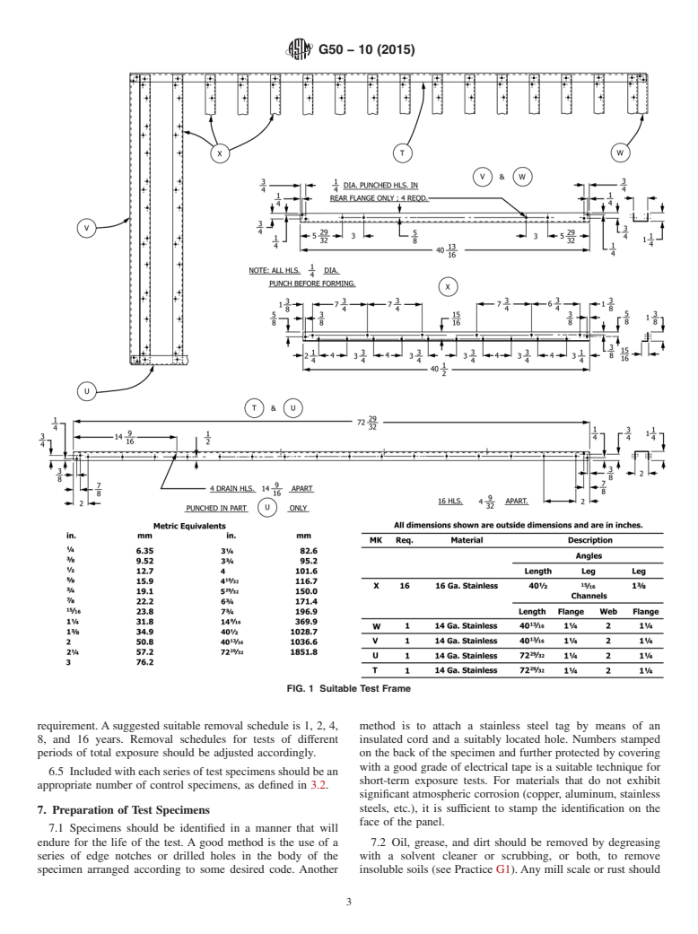
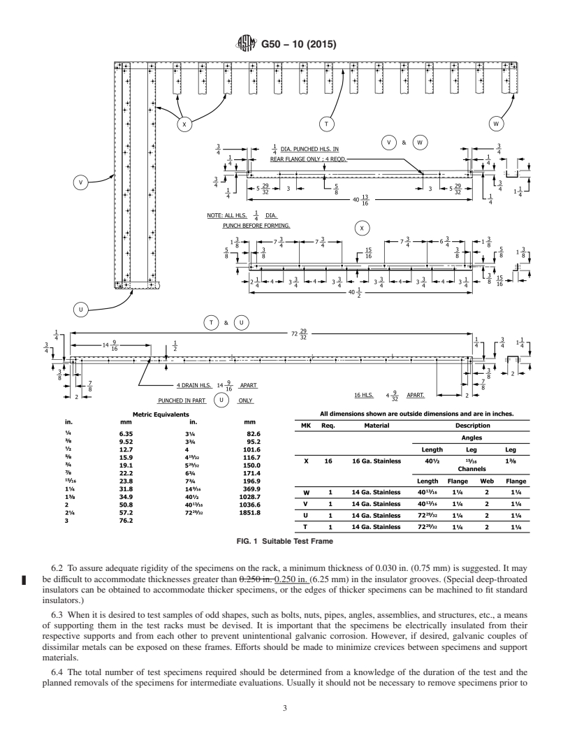
5.4 A suitable frame for mounting the insulators is shown in Fig. 1. This frame will accommodate 70 standard 4 by 6-in. (100
by 150-mm) specimens; other sizes can be mounted by rearranging the insulators in the holes provided. It is acceptable to slot the
holes in the frames in such a manner that the mounting frames are adjustable for specimens of other sizes. This is a convenience
when it is not possible to prepare specimens of a preplanned size, and it is often helpful in fitting the specimens snugly into the
frames.
5.5 The racks should be designed to give exposure to as large an area of the underside of the specimens as possible. Structural
members of the rack should not be located directly under the specimens where they would shelter the underside of the specimens.
5.6 As most published data on atmospheric corrosion of metals are based on an exposure angle of 30° from the horizontal,
facing south, it is recommended that this angle be used. Racks should be designed so that the lowest specimens are at least 30 in.
(760 mm) above the ground. See Notes 2 and 3.
NOTE 2—Maximum exposure to the sun may be obtained by exposing specimens facing south (for the northern hemisphere) at an angle equal to the
latitude of the test site. Exposure at this angle will yield the lowest corrosion rates for most materials. Although these corrosion rates will change at other
angles of exposure, the order of merit established for each material will be the same.
NOTE 3—In special instances, it may be desirable to orient racks and frames in the direction of a specific corrodent source, for example, the ocean,
for marine environments. Also, this practice should not be construed as prohibiting special orientation of test frames for specific test purposes, but it is
strongly suggested that in such cases testing also be done in accordance with this practice so that a basis point for comparison with available data is
determined. Any special orientation or preferential source of corrosion should be specifically identified in the exposure site description.
5.7 A rack of the design and dimensions shown in Fig. 2 will give the correct exposure angle and can support the specimen
frame described in 5.4.
5.8 The ground under the racks should be kept free of weeds, bushes, and debris. Organic herbicides, defoliants, or pesticides
should not be used for this purpose.
6. Test Specimens
6.1 When the material to be tested is in sheet form, a specimen size of 4 by 6 in. (100 by 150 mm) is appropriate. Specimens
may be larger, for example, 4 by 8 in. (100 by 200 by 200 mm), to suit a particular test; however, the specimens preferably should
not be smaller than 4 by 6 in.
G50 − 10 (2015)
FIG. 1 Suitable Test Frame
6.2 To assure adequate rigidity of the specimens on the rack, a minimum thickness of 0.030 in. (0.75 mm) is suggested. It may
be difficult to accommodate thicknesses greater than 0.250 in. 0.250 in. (6.25 mm) in the insulator grooves. (Special deep-throated
insulators can be obtained to accommodate thicker specimens, or the edges of thicker specimens can be machined to fit standard
insulators.)
6.3 When it is desired to test samples of odd shapes, such as bolts, nuts, pipes, angles, assemblies, and structures, etc., a means
of supporting them in the test racks must be devised. It is important that the specimens be electrically insulated from their
respective supports and from each other to prevent unintentional galvanic corrosion. However, if desired, galvanic couples of
dissimilar metals can be exposed on these frames. Efforts should be made to minimize crevices between specimens and support
materials.
6.4 The total number of test specimens required should be determined from a knowledge of the duration of the test and the
planned removals of the specimens for intermediate evaluations. Usually it should not be necessary to remove specimens prior to
G50 − 10 (2015)
NOTE 1—Items 1, 2, 3, 4, 5, and 8 are 1 ⁄4-in. (31.8-mm) hot-dip galvanized pipe.
NOTE 2—Fill all legs with concrete to about 6 in. (152 mm) above ground line.
Metric Equivalents
ft-in. m ft-in. m Req. Item Name
0-0 0.254 3-7 1.092 12 10 Plugs
1-7 0.483 5-5 ⁄8 1.654 8 9 4-way fittings
1-10 ⁄4 0.565 6-1 1.854 26 8 Tees
1 3
1-10.5 0.572 6-6 ⁄8 1.984 4 5 Joining braces 28 ⁄4 in. L
2-2 0.660 9-0 2.743 7 4 Cross braces 22 ⁄4 in. L
3 1 1
2-4 ⁄4 0.730 11-9 ⁄2 3.594 10 3 Stringers 11 ft –9 ⁄2 in. L
2-6 0.762 12-2 3.708 6 2 Front legs 5 ft – 5 ⁄8 in. L
3-0 0.914 60-10 18.542 6 1 Back legs 6 ft – 6 ⁄8 in. L
FIG. 2 Suitable Test Rack Support
completing one year’s exposure, unless specific data are required for corrosion occurring during earlier stages of exposure. For
reliable results, sufficient specimens should be used for multiple removals at each exposure period. Triplicate specimens for each
examination period will usually satisfy this requirement. A suggested suitable removal schedule is 1, 2, 4, 8, and 16 years. Removal
schedules for tests of different periods of total exposure should be adjusted accordingly.
6.5 Included with each series of test specimens should be an appropriate number of control specimens, as defined in 3.2.
7. Preparation of Test Specimens
7.1 Specimens should be identified in a manner that will endure for the life of the test. A good method is the use of a series
of edge notches or drilled holes in the body of the specimen arranged according to some desired code. Another method is to attach
a stainless steel tag by means of an insulated cord and a suitably located hole. Numbers stamped on the back of the specimen and
further protected by covering with a good grade of electrical tape is a suitable technique for short-term exposure tests. For materials
that do not exhibit significant atmospheric corrosion (copper, aluminum, stainless steels, etc.), it is sufficient to stamp the
identification on the face of the panel.
7.2 Oil, grease, and dirt should be removed by degreasing with a solvent cleaner or scrubbing, or both, to remove insoluble soils
(see Practice G1). Any mill scale or rust should be removed from all ferrous specimens unless it is specifically desired to perform
the test with the mill scale intact. Pickling with inhibited acid as well as blasting with sand or grit are acceptable descaling methods.
If acid pickling is used, care must be taken to stop the pickling action as soon as the mill scale and rust have been removed.
Stainless steels should be pickled in accordance with Practice A380 to ensure surfaces free of iron contamination.
7.3 Specimens should be weighed to at least the nearest 0.01 g 0.01 g before exposure. More corrosion-resistant materials are
frequently weighed to the nearest 0.1 mg. When deemed appropriate, the specimens should be photographed to take into account
pre-exposure surface defects. Records should be kept of the weight, dimensions, and appearance of each specimen at the beginning
of the test. Data to be recorded prior to exposure are explicitly outlined in Practice G33. Changes in the physical appearance an
...
Questions, Comments and Discussion
Ask us and Technical Secretary will try to provide an answer. You can facilitate discussion about the standard in here.