


ASTM D7671-10(2015)
(Test Method)Standard Test Method for Corrosiveness to Silver by Automotive Spark–Ignition Engine Fuel–Silver Strip Method
Standard Test Method for Corrosiveness to Silver by Automotive Spark–Ignition Engine Fuel–Silver Strip Method
SIGNIFICANCE AND USE
4.1 Crude petroleum contains sulfur compounds, most of which are removed during refining. However, of the sulfur compounds remaining in the petroleum product, some can have a corroding action on various metals and this corrosivity is not related to the total sulfur content. In addition, fuels can become contaminated by corrosive sulfur compounds during storage and distribution. The corrosive effect can vary according to the chemical types of sulfur compounds present.
4.2 The silver strip corrosion test is designed to assess the relative degree of corrosivity of a petroleum product towards silver and silver alloys.
4.3 Reactive sulfur compounds present in automotive spark-ignition engine fuels under some circumstances can corrode or tarnish silver alloy fuel gauge in-tank sender units (and silver-plated bearings in some 2-stroke cycle engines). To minimize or prevent the failure of silver alloy in-tank sender units by corrosion or tarnish, Specification D4814 requires that fuels shall pass the silver strip corrosion test.
SCOPE
1.1 This test method covers the determination of the corrosiveness to silver by automotive spark-ignition engine fuel, as defined by Specification D4814, or similar specifications in other jurisdictions, having a vapor pressure no greater than 124 kPa (18 psi) at 37.8 °C (100 °F), by one of two procedures. Procedure A involves the use of a pressure vessel, whereas Procedure B involves the use of a vented test tube.
1.2 The result of the test is based on a visual rating that is classified as an integer in the range from 0 to 4 as defined in Table 1.
1.3 The values stated in SI units are to be regarded as the standard. The values in parentheses are for information only.
1.4 This standard does not purport to address all of the safety concerns, if any, associated with its use. It is the responsibility of the user of this standard to establish appropriate safety and health practices and determine the applicability of regulatory limitations prior to use. For specific warning statements, see 6.1 and Section 7.
General Information
Buy Standard
Standards Content (Sample)
NOTICE: This standard has either been superseded and replaced by a new version or withdrawn.
Contact ASTM International (www.astm.org) for the latest information
Designation: D7671 − 10 (Reapproved 2015)
Standard Test Method for
Corrosiveness to Silver by Automotive Spark–Ignition
Engine Fuel–Silver Strip Method
This standard is issued under the fixed designation D7671; the number immediately following the designation indicates the year of
original adoption or, in the case of revision, the year of last revision.Anumber in parentheses indicates the year of last reapproval.A
superscript epsilon (´) indicates an editorial change since the last revision or reapproval.
1. Scope E1Specification for ASTM Liquid-in-Glass Thermometers
2.2 Energy Institute Standard:
1.1 This test method covers the determination of the corro-
IP227Determination of Corrosiveness to Silver ofAviation
siveness to silver by automotive spark-ignition engine fuel, as
Turbine Fuels–Silver Strip Method
defined by Specification D4814, or similar specifications in
other jurisdictions, having a vapor pressure no greater than
2.3 ASTM Adjuncts:
124kPa(18psi)at37.8°C(100°F),byoneoftwoprocedures.
Color Standard for Tube Deposit Rating
Procedure A involves the use of a pressure vessel, whereas
Procedure B involves the use of a vented test tube.
3. Summary of Test Method
1.2 The result of the test is based on a visual rating that is 3.1 This test method covers two procedures. Procedure A
classified as an integer in the range from 0 to 4 as defined in
involves the use of a pressure vessel (to prevent the loss of
Table 1. volatile components in the sample), whereas Procedure B
involves the use of a vented test tube. In both procedures, a
1.3 The values stated in SI units are to be regarded as the
freshly polished silver strip is suspended in 30mL of sample
standard. The values in parentheses are for information only.
whichisheatedto50°C 61°Cforadurationof3h 65min.
1.4 This standard does not purport to address all of the
At the end of the heating period, the silver strip is removed,
safety concerns, if any, associated with its use. It is the
washed and the color and tarnish level assessed against the
responsibility of the user of this standard to establish appro-
requirements in Table 1.
priate safety and health practices and determine the applica-
bility of regulatory limitations prior to use. For specific
4. Significance and Use
warning statements, see 6.1 and Section 7.
4.1 Crude petroleum contains sulfur compounds, most of
2. Referenced Documents which are removed during refining. However, of the sulfur
2 compoundsremaininginthepetroleumproduct,somecanhave
2.1 ASTM Standards:
a corroding action on various metals and this corrosivity is not
D130Test Method for Corrosiveness to Copper from Petro-
relatedtothetotalsulfurcontent.Inaddition,fuelscanbecome
leum Products by Copper Strip Test
contaminated by corrosive sulfur compounds during storage
D3241Test Method for Thermal Oxidation Stability of
and distribution.The corrosive effect can vary according to the
Aviation Turbine Fuels
chemical types of sulfur compounds present.
D4057Practice for Manual Sampling of Petroleum and
Petroleum Products 4.2 The silver strip corrosion test is designed to assess the
D4177Practice for Automatic Sampling of Petroleum and relative degree of corrosivity of a petroleum product towards
Petroleum Products silver and silver alloys.
D4814Specification for Automotive Spark-Ignition Engine
4.3 Reactivesulfurcompoundspresentinautomotivespark-
Fuel
ignition engine fuels under some circumstances can corrode or
tarnish silver alloy fuel gauge in-tank sender units (and
1 silver-plated bearings in some 2-stroke cycle engines). To
This test method is under the jurisdiction of ASTM Committee D02 on
Petroleum Products, Liquid Fuels, and Lubricants and are the direct responsibility
minimize or prevent the failure of silver alloy in-tank sender
of Subcommittee D02.05.0C on Color and Reactivity.
Current edition approved Oct. 1, 2015. Published December 2015. Originally
ɛ1
approved in 2010. Last previous edition approved in 2010 as D7671–10 . DOI:
10.1520/D7671-10R15. Withdrawn without replacement in 2001. Copies of IP 227/99 can be obtained
For referenced ASTM standards, visit the ASTM website, www.astm.org, or at The Publications Department, Energy Institute, 61 New Cavendish Street,
contact ASTM Customer Service at service@astm.org. For Annual Book of ASTM London, W1G 7AR, United Kingdom.
Standards volume information, refer to the standard’s Document Summary page on Available from ASTM International Headquarters. Order Adjunct No.
the ASTM website. ADJD3241. Original adjunct produced in 1986.
Copyright © ASTM International, 100 Barr Harbor Drive, PO Box C700, West Conshohocken, PA 19428-2959. United States
D7671 − 10 (2015)
TABLE 1 Silver Strip Classifications
NOTE 1—Classifications provided by IP 227 Determination of Corro-
siveness to Silver of Aviation Turbine Fuels–Silver Strip Method.
NOTE 2—Distinctions between Classifications 1 and 2 are made using
The Color Standard for Tube Deposit Rating (referenced in Test Method
D3241) in accordance with 11.1.1.
Classification Designation Description
0 No tarnish Identical to a freshly pol-
ished strip, but may have
some very light loss of lus-
ter
1 Slight tarnish Faint brown or white discol-
oration of strip (see 12.1)
2 Moderate tarnish Peacock colors such as
blue or mauve or medium/
dark straw or brown color-
ation (see 12.1)
3 Slight blackening Spots and patches of black
or gray on surface or uni-
form thin film of black de-
posit
4 Blackening Uniform heavy blackening
with or without scaling
Key:
unitsbycorrosionortarnish,SpecificationD4814requiresthat
1. Lifting eye
fuels shall pass the silver strip corrosion test.
2. Wide groove for pressure relief
3. Knurled cap
4. Twelve threads per inch NF thread or equivalent
5. Apparatus
5. Camber inside cap to protect “O” ring when closing pressure vessel
5.1 Silver Strip Corrosion Pressure Vessel (Procedure A),
6. Synthetic rubber “O” ring without free sulfur
7. Seamless tube
constructed from stainless steel or similar strong and non-
Material: stainless steel
corroding metallurgy according to the dimensions as given in
Welded construction
Fig. 1, that is the apparatus described in Test Method D130. Maximum test gauge pressure: 700 kPa
The vessel shall be capable of withstanding a test pressure of
NOTE 1—Dimensions in millimetres.
700kPa gauge (100psi).
NOTE 2—All dimensions without tolerance limits are nominal values.
5.1.1 Alternative designs for the vessel’s cap and synthetic
FIG. 1 Pressure Vessel for Silver Strip Corrosion Test
rubber gasket may be used provided that the internal dimen-
(Procedure A)
sions of the vessel are the same as those shown in Fig. 1. The
internal dimensions of the pressure vessel are such that a
5.4.2 For Procedure B, a cable tie (see 6.2) wrapped around
nominal 25mm by 150mm test tube can be placed inside the
theedgesofthestripandinsertedthroughthestopperhasbeen
pressure vessel.
found suitable to use for this purpose as shown in Fig. 3.
5.2 Test Tubes, of borosilicate glass of nominal 25mm by
5.4.3 Other assemblies or designs capable of meeting the
150mm dimensions.The internal dimensions shall be checked
functional requirement may also be used in ProceduresAor B.
as acceptable by use of a silver strip (see 6.3).When 30mLof
5.5 Test Bath:
liquid is added to the test tube with the silver strip in it, a
5.5.1 General—The test baths shall be able to maintain the
minimum of 5mm of liquid shall be above the top surface of
test temperature to within 61°C (2°F) of the required test
the strip.
temperature (normally 50ºC).
5.3 Stoppers(ProcedureB),suchascork,toaccompanytest
5.5.2 Liquid Bath Used for Submerging Pressure Vessel(s)
tubes in 5.2. Each stopper shall have a vent hole to equilibrate
(Procedure A)—The bath shall be deep enough to submerge
pressure that may build up in the test. The stoppers should be
one or more pressure vessels (see 5.1) completely during the
drilled through the center and fitted with a length of 3.2mm
test. As the bath medium, use water or any liquid that can be
( ⁄8in.) OD glass or Nalgene vent tube.
satisfactorily controlled to the sample test temperature. The
5.4 Silver Strip Suspension Assembly, such as examples bath shall be fitted with suitable supports to hold each pressure
showninFig.2(ProcedureA)orFig.3(ProcedureB),capable vesselinaverticalpositionwhensubmerged.Theuseofasolid
ofsuspendingthesilverstripinapproximatelythecenterofthe blockbathhasbeenfoundasasuitablealternativetotheliquid
sample-filledtesttubeduringthetest,suchthatthestripiskept bath.
in an upright and vertical position. 5.5.3 Liquid Bath Used for Vented Test Tube Method (Pro-
5.4.1 For ProcedureA, a cradle of glass, polytetrafluoroeth- cedure B)—The bath liquid level shall be at a level that is
ylene or other inert material connected to a holder of sufficient higher than the liquid level in the test tube at the test
length and width as shown in Fig. 2 has been found suitable to temperature. It is recommended that the bath be placed inside
use. an exhaust hood.
D7671 − 10 (2015)
5.5.4 The use of a solid block bath has been found to be a
suitable alternative to the liquid bath.
5.6 Temperature Sensing Device (TSD),capableofmonitor-
ing the desired test temperature in the bath to within accuracy
of 61°C(2°F),measuredinthemiddleoftheliquidbath.The
ASTM 12C (12F) (see Specification E1) orASTM E2251 (see
Specification E1) or IP 64C (64F) total immersion thermom-
eters have been found suitable for use in the test. If used, no
morethan10mm(0.4in.)ofthemercuryshouldextendabove
the surface of the bath at the test temperature.
5.7 PolishingVise,forholdingthesilverstripfirmlywithout
marring the edges while polishing. Any convenient type of
holder (see Appendix X1) may be used provided that the strip
isheldtightlyandthatthesurfaceofthestripbeingpolishedis
supported above the surface of the holder.
5.8 Viewing Test Tubes, (optional) flat glass test tubes, are
convenient for protecting corroded silver strips for close
inspection or storage (see Appendix X1 for the description of
a flat-glass viewing tube). The viewing test tube shall be of
such dimensions as to allow the introduction of a silver strip
(see 6.3) and made of glass free of striae or similar defects.
5.9 Forceps, with either stainless steel or polytetrafluoro-
ethylene tips, for use in handling the silver strips, have been
FIG. 2 Silver Strip Suspension Assembly (Procedure A)
found suitable to use.
5.10 Timing Device, electronic or manual, capable of accu-
rately measuring the test duration within the allowable toler-
ance.
5.11 ASTM Silver Strip Corrosion Standards, consist of
reproductions in color of typical test strips representing in-
creasing degrees of tarnish and corrosion, the reproductions
beingencasedforprotectioninplasticandmadeupintheform
of a plaque. See Table 1.
5.11.1 Keep the plastic-encased ASTM Silver Strip Corro-
sion Standards protected from light to avoid the possibility of
fading. Inspect for fading by comparing two different plaques,
one of which has been carefully protected from light (for
example, new plaque). Observe both sets in diffused daylight
(or equivalent) first from a point directly above and then from
an angle of 45°. If any evidence of fading is observed,
particularly at the left-hand end of the plaque, it is suggested
that the one that is the more faded with respect to the other be
discarded.
5.11.1.1 Alternatively, place a suitably sized opaque strip
(for example, 20mm ( ⁄4in.) black electrical tape) across the
top of the colored portion of the plaque when initially
purchased. At intervals remove the opaque strip and observe.
When there is any evidence of fading of the exposed portion,
Key: the standards shall be replaced.
1. Stopper
5.11.2 The plaques are full-color reproductions of typical
2. Vent tube
3. Cable tie strips.Theyhavebeenprintedonaluminumsheetsbya4-color
4. Silver strip
processandareencasedinplasticforprotection.Directionsfor
5. Test tube
their use are given on the reverse side of each plaque.
FIG. 3 Silver Strip Suspension Assembly (Procedure B)
5.11.3 If the surface of the plastic cover shows excessive
scratching, it is suggested that the plaque be replaced.
D7671 − 10 (2015)
6. Reagents and Materials mediumrapidqualitativefilterpaper,intotheprescribedclean,
dry test tube. Carry out this operation in a darkened room or
6.1 Ashless Filter Paper or Disposable Gloves, for use in
under a light-protected shield.
protecting the silver strip from coming in contact with the
8.4.1 Contact of the silver strip with water before, during or
individual during final polishing.
after completion of the test run will cause staining, making it
6.2 Cable Tie—Inert ties such as nylon ties of approximate
difficult to evaluate the strips.
dimensions 2mm × 208mm.
6.3 Silver Strips—Use strips 12.5mm to 12.7mm wide, 9. Preparation of Test Strips
2.5mm to 3.0mm thick, and 17.0mm to 19.0mm long
9.1 Surface Preparation—Remove all surface blemishes
assaying at 99.9% (m⁄m) Ag minimum, which are the same
fromallsixsidesofthestripobtainedfromapreviousanalysis
specification requirements described in IP227. The strips may
(seeNote1).Usesiliconcarbidepaperorclothofsuchdegrees
be used repeatedly but should be discarded when the strip’s
of fineness as are needed to accomplish the desired results
surfaceshowspittingordeepscratchesthatcannotberemoved
efficiently. Finish with 53µm to 65µm (240grit) silicon
by the specified polishing procedure, or when the surface
carbide paper or cloth, removing all marks that may have been
becomes deformed.
made by other grades of paper used previously. Immerse the
6.4 Surface Preparation/Polishing Materials, silicon car- stripin2,2,4-trimethylpentanefromwhichitcanbewithdrawn
bidegritpaperorclothofvaryingdegreesoffinenessincluding
immediatelyforfinalpreparation(polishing)orinwhichitcan
53µm to 65µm (240grit) grade; also a supply of 105µm be stored for future use.
(150mesh) size silicon carbide grain or powder and absorbent
9.1.1 As a practical manual procedure for surface
cotton (cotton wool). A commercial grade of absorbent cotton preparation, place a sheet of silicon carbide paper or cloth on
is suitable, but pharmaceutical grade is most commonly avail-
a flat surface and moisten it with wash solvent. Rub the strip
able and is acceptable. against the silicon carbide paper or cloth with a circular
motion, protecting the strip from contact with the fingers by
6.5 Wash Solvent—2,2,4-trimethylpentane (isooctane) of
using ashless filter paper or wearing disposable gloves.
minimum 99.75% purity. (Warning—Extremely flammable.
Alternatively, the surface of the strip may be prepared by use
See 7.1.)
of motor-driven machines using
...
This document is not an ASTM standard and is intended only to provide the user of an ASTM standard an indication of what changes have been made to the previous version. Because
it may not be technically possible to adequately depict all changes accurately, ASTM recommends that users consult prior editions as appropriate. In all cases only the current version
of the standard as published by ASTM is to be considered the official document.
´1
Designation: D7671 − 10 D7671 − 10 (Reapproved 2015)
Standard Test Method for
Corrosiveness to Silver by Automotive Spark–Ignition
Engine Fuel–Silver Strip Method
This standard is issued under the fixed designation D7671; the number immediately following the designation indicates the year of
original adoption or, in the case of revision, the year of last revision. A number in parentheses indicates the year of last reapproval. A
superscript epsilon (´) indicates an editorial change since the last revision or reapproval.
ε NOTE—Corrected unit in 9.2.1 editorially in July 2012.
1. Scope
1.1 This test method covers the determination of the corrosiveness to silver by automotive spark-ignition engine fuel, as defined
by Specification D4814, or similar specifications in other jurisdictions, having a vapor pressure no greater than 124 kPa (18 psi)
at 37.8°C (100°F),(18 psi) at 37.8 °C (100 °F), by one of two procedures. Procedure A involves the use of a pressure vessel,
whereas Procedure B involves the use of a vented test tube.
1.2 The result of the test is based on a visual rating that is classified as an integer in the range from 0 to 4 as defined in Table
1.
1.3 The values stated in SI units are to be regarded as the standard. The values in parentheses are for information only.
1.4 This standard does not purport to address all of the safety concerns, if any, associated with its use. It is the responsibility
of the user of this standard to establish appropriate safety and health practices and determine the applicability of regulatory
limitations prior to use. For specific warning statements, see 6.1 and Section 7.
2. Referenced Documents
2.1 ASTM Standards:
D130 Test Method for Corrosiveness to Copper from Petroleum Products by Copper Strip Test
D3241 Test Method for Thermal Oxidation Stability of Aviation Turbine Fuels
D4057 Practice for Manual Sampling of Petroleum and Petroleum Products
D4177 Practice for Automatic Sampling of Petroleum and Petroleum Products
D4814 Specification for Automotive Spark-Ignition Engine Fuel
E1 Specification for ASTM Liquid-in-Glass Thermometers
2.2 Energy Institute Standard:
IP 227 Determination of Corrosiveness to Silver of Aviation Turbine Fuels–Silver Strip Method
2.3 ASTM Adjuncts:
Color Standard for Tube Deposit Rating
3. Summary of Test Method
3.1 This test method covers two procedures. Procedure A involves the use of a pressure vessel (to prevent the loss of volatile
components in the sample), whereas Procedure B involves the use of a vented test tube. In both procedures, a freshly polished silver
strip is suspended in 30 mL 30 mL of sample which is heated to 5050 °C 6 1°C1 °C for a duration of 3 h 6 5 min. 3 h 6 5 min.
At the end of the heating period, the silver strip is removed, washed and the color and tarnish level assessed against the
requirements in Table 1.
This test method is under the jurisdiction of ASTM Committee D02 on Petroleum Products, Liquid Fuels, and Lubricants and are the direct responsibility of
Subcommittee D02.05.0C on Color and Reactivity.
Current edition approved Oct. 1, 2010Oct. 1, 2015. Published November 2010December 2015. Originally approved in 2010. Last previous edition approved in 2010 as
ɛ1
D7671 – 10 . DOI: 10.1520/D7671–10.10.1520/D7671-10R15.
For referenced ASTM standards, visit the ASTM website, www.astm.org, or contact ASTM Customer Service at service@astm.org. For Annual Book of ASTM Standards
volume information, refer to the standard’s Document Summary page on the ASTM website.
Withdrawn without replacement in 2001. Copies of IP 227/99 can be obtained at The Publications Department, Energy Institute, 61 New Cavendish Street, London, W1G
7AR, United Kingdom.
Available from ASTM International Headquarters. Order Adjunct No. ADJD3241. Original adjunct produced in 1986.
Copyright © ASTM International, 100 Barr Harbor Drive, PO Box C700, West Conshohocken, PA 19428-2959. United States
D7671 − 10 (2015)
TABLE 1 Silver Strip Classifications
NOTE 1—Classifications provided by IP 227 Determination of Corro-
siveness to Silver of Aviation Turbine Fuels–Silver Strip Method.
NOTE 2—Distinctions between Classifications 1 and 2 are made using
The Color Standard for Tube Deposit Rating (referenced in Test Method
D3241) in accordance with 11.1.1.
Classification Designation Description
0 No tarnish Identical to a freshly pol-
ished strip, but may have
some very light loss of lus-
ter
1 Slight tarnish Faint brown or white discol-
oration of strip (see 12.1)
2 Moderate tarnish Peacock colors such as
blue or mauve or medium/
dark straw or brown color-
ation (see 12.1)
3 Slight blackening Spots and patches of black
or gray on surface or uni-
form thin film of black de-
posit
4 Blackening Uniform heavy blackening
with or without scaling
4. Significance and Use
4.1 Crude petroleum contains sulfur compounds, most of which are removed during refining. However, of the sulfur compounds
remaining in the petroleum product, some can have a corroding action on various metals and this corrosivity is not related to the
total sulfur content. In addition, fuels can become contaminated by corrosive sulfur compounds during storage and distribution.
The corrosive effect can vary according to the chemical types of sulfur compounds present.
4.2 The silver strip corrosion test is designed to assess the relative degree of corrosivity of a petroleum product towards silver
and silver alloys.
4.3 Reactive sulfur compounds present in automotive spark-ignition engine fuels under some circumstances can corrode or
tarnish silver alloy fuel gauge in-tank sender units (and silver-plated bearings in some 2-stroke cycle engines). To minimize or
prevent the failure of silver alloy in-tank sender units by corrosion or tarnish, Specification D4814 requires that fuels shall pass
the silver strip corrosion test.
5. Apparatus
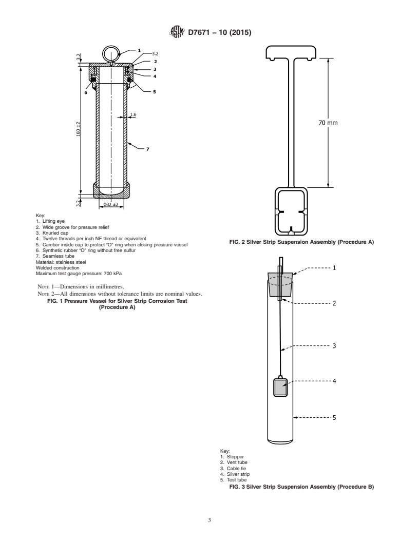
5.1 Silver Strip Corrosion Pressure Vessel (Procedure A), constructed from stainless steel or similar strong and non-corroding
metallurgy according to the dimensions as given in Fig. 1, that is the apparatus described in Test Method D130. The vessel shall
be capable of withstanding a test pressure of 700 kPa gauge (100 psi).700 kPa gauge (100 psi).
5.1.1 Alternative designs for the vessel’s cap and synthetic rubber gasket may be used provided that the internal dimensions of
the vessel are the same as those shown in Fig. 1. The internal dimensions of the pressure vessel are such that a nominal
25-mm25 mm by 150-mm150 mm test tube can be placed inside the pressure vessel.
5.2 Test Tubes, of borosilicate glass of nominal 25-mm25 mm by 150-mm150 mm dimensions. The internal dimensions shall
be checked as acceptable by use of a silver strip (see 6.3). When 30 mL 30 mL of liquid is added to the test tube with the silver
strip in it, a minimum of 5-mm5 mm of liquid shall be above the top surface of the strip.
5.3 Stoppers (Procedure B), such as cork, to accompany test tubes in 5.2. Each stopper shall have a vent hole to equilibrate
pressure that may build up in the test. The stoppers should be drilled through the center and fitted with a length of 3.2 mm 3.2 mm
( ⁄8 in.) OD glass or Nalgene vent tube.
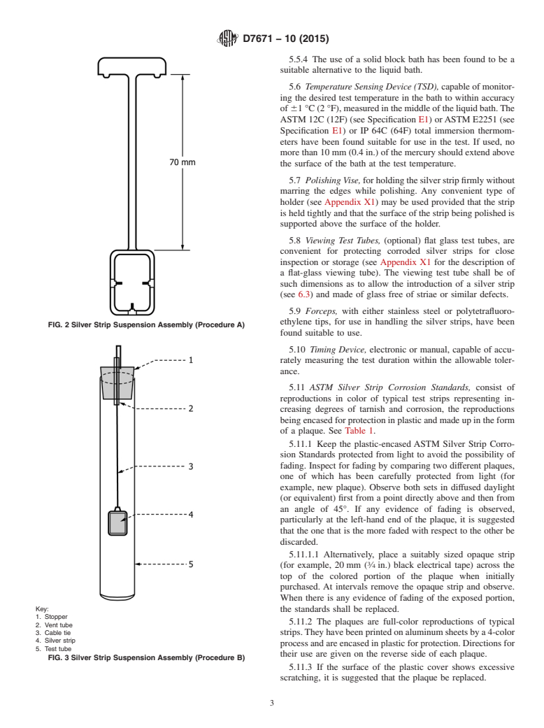
5.4 Silver Strip Suspension Assembly, such as examples shown in Fig. 2 (Procedure A) or Fig. 3 (Procedure B), capable of
suspending the silver strip in approximately the center of the sample-filled test tube during the test, such that the strip is kept in
an upright and vertical position.
5.4.1 For Procedure A, a cradle of glass, polytetrafluoroethylene or other inert material connected to a holder of sufficient length
and width as shown in Fig. 2 has been found suitable to use.
5.4.2 For Procedure B, a cable tie (see 6.2) wrapped around the edges of the strip and inserted through the stopper has been
found suitable to use for this purpose as shown in Fig. 3.
5.4.3 Other assemblies or designs capable of meeting the functional requirement may also be used in Procedures A or B.
5.5 Test Bath:
D7671 − 10 (2015)
Key:
1. Lifting eye
2. Wide groove for pressure relief
3. Knurled cap
4. Twelve threads per inch NF thread or equivalent
FIG. 2 Silver Strip Suspension Assembly (Procedure A)
5. Camber inside cap to protect “O” ring when closing pressure vessel
6. Synthetic rubber “O” ring without free sulfur
7. Seamless tube
Material: stainless steel
Welded construction
Maximum test gauge pressure: 700 kPa
NOTE 1—Dimensions in millimetres.
NOTE 2—All dimensions without tolerance limits are nominal values.
FIG. 1 Pressure Vessel for Silver Strip Corrosion Test
(Procedure A)
Key:
1. Stopper
2. Vent tube
3. Cable tie
4. Silver strip
5. Test tube
FIG. 3 Silver Strip Suspension Assembly (Procedure B)
D7671 − 10 (2015)
5.5.1 General—The test baths shall be able to maintain the test temperature to within 61°C (2°F)61 °C (2 °F) of the required
test temperature (normally 50ºC).50 ºC).
5.5.2 Liquid Bath Used for Submerging Pressure Vessel(s) (Procedure A)—The bath shall be deep enough to submerge one or
more pressure vessels (see 5.1) completely during the test. As the bath medium, use water or any liquid that can be satisfactorily
controlled to the sample test temperature. The bath shall be fitted with suitable supports to hold each pressure vessel in a vertical
position when submerged. The use of a solid block bath has been found as a suitable alternative to the liquid bath.
5.5.3 Liquid Bath Used for Vented Test Tube Method (Procedure B)—The bath liquid level shall be at a level that is higher than
the liquid level in the test tube at the test temperature. It is recommended that the bath be placed inside an exhaust hood.
5.5.4 The use of a solid block bath has been found to be a suitable alternative to the liquid bath.
5.6 Temperature Sensing Device (TSD), capable of monitoring the desired test temperature in the bath to within accuracy of
61°C (2°F),61 °C (2 °F), measured in the middle of the liquid bath. The ASTM 12C (12F) (see Specification E1) or ASTM E2251
(see Specification E1) or IP 64C (64F) total immersion thermometers have been found suitable for use in the test. If used, no more
than 10-mm (0.4-in.)10 mm (0.4 in.) of the mercury should extend above the surface of the bath at the test temperature.
5.7 Polishing Vise, for holding the silver strip firmly without marring the edges while polishing. Any convenient type of holder
(see Appendix X1) may be used provided that the strip is held tightly and that the surface of the strip being polished is supported
above the surface of the holder.
5.8 Viewing Test Tubes, (optional) flat glass test tubes, are convenient for protecting corroded silver strips for close inspection
or storage (see Appendix X1 for the description of a flat-glass viewing tube). The viewing test tube shall be of such dimensions
as to allow the introduction of a silver strip (see 6.3) and made of glass free of striae or similar defects.
5.9 Forceps, with either stainless steel or polytetrafluoroethylene tips, for use in handling the silver strips, have been found
suitable to use.
5.10 Timing Device, electronic or manual, capable of accurately measuring the test duration within the allowable tolerance.
5.11 ASTM Silver Strip Corrosion Standards, consist of reproductions in color of typical test strips representing increasing
degrees of tarnish and corrosion, the reproductions being encased for protection in plastic and made up in the form of a plaque.
See Table 1.
5.11.1 Keep the plastic-encased ASTM Silver Strip Corrosion Standards protected from light to avoid the possibility of fading.
Inspect for fading by comparing two different plaques, one of which has been carefully protected from light (for example, new
plaque). Observe both sets in diffused daylight (or equivalent) first from a point directly above and then from an angle of 45°. If
any evidence of fading is observed, particularly at the left-hand end of the plaque, it is suggested that the one that is the more faded
with respect to the other be discarded.
5.11.1.1 Alternatively, place a suitably sized opaque strip (for example, 20-mm20 mm ( ⁄4-in.) in.) black electrical tape) across
the top of the colored portion of the plaque when initially purchased. At intervals remove the opaque strip and observe. When there
is any evidence of fading of the exposed portion, the standards shall be replaced.
5.11.2 The plaques are full-color reproductions of typical strips. They have been printed on aluminum sheets by a 4-color
process and are encased in plastic for protection. Directions for their use are given on the reverse side of each plaque.
5.11.3 If the surface of the plastic cover shows excessive scratching, it is suggested that the plaque be replaced.
6. Reagents and Materials
6.1 Ashless Filter Paper or Disposable Gloves, for use in protecting the silver strip from coming in contact with the individual
during final polishing.
6.2 Cable Tie—Inert ties such as nylon ties of approximate dimensions 2 mm × 208 mm.2 mm × 208 mm.
6.3 Silver Strips—Use strips 12.512.5 mm to 12.7-mm12.7 mm wide, 2.52.5 mm to 3.0-mm3.0 mm thick, and 17.017.0 mm to
19.0-mm19.0 mm long assaying at 99.9 % (m/m)(m ⁄m) Ag minimum, which are the same specification requirements described in
IP 227. The strips may be used repeatedly but should be discarded when the strip’s surface shows pitting or deep scratches that
cannot be removed by the specified polishing procedure, or when the surface becomes deformed.
6.4 Surface Preparation/Polishing Materials, silicon carbide grit paper or cloth of varying degrees of fineness including
5353 μm to 65-μm (240-grit)65 μm (240 grit) grade; also a supply of 105-μm (150-mesh)105 μm (150 mesh) size silicon carbide
grain or powder and absorbent cotton (cotton wool). A commercial grade of absorbent cotton is suitable, but pharmaceutical grade
is most commonly available and is acceptable.
6.5 Wash Solvent—2,2,4-trimethylpentane (isooctane) of minimum 99.75 % purity. (Warning—Extremely flammable. See 7.1.)
7. Hazards
7.1 Wash Solvent—2,2,4-trimethylpentane (isooctane): Harmful if inhaled. Use with adequate ventilation. Keep away from heat,
sparks, and open flame. Avoid prolonged or repeated skin contact. Consult MSDS for additional information.
D7671 − 10 (2015)
7.2 Automotive Spark-Ignition Fuel (typically gasoline)—Harmful if inhaled. Use with adequate ventilation.
...
Questions, Comments and Discussion
Ask us and Technical Secretary will try to provide an answer. You can facilitate discussion about the standard in here.