


ASTM A861-04(2017)
(Specification)Standard Specification for High-Silicon Iron Pipe and Fittings
Standard Specification for High-Silicon Iron Pipe and Fittings
ABSTRACT
This specification covers high-silicon iron pipe and pipe fittings intended for corrosion-resistant service for both above- and below-grade construction. The castings shall be true to pattern, reasonable smooth, and free from defects that would make the castings unfit for the use for which they are intended. The material shall conform to the chemical composition requirements specified. All centrifugally cast high-silicon iron pipe shall be supplied in the as-cast condition. All other pipe and fittings shall be supplied in the stress-relieved condition; the stress relieving procedures are presented. Acid-proof joints for hub/plain-end pipe shall require the use of an acid-proof rope packing. No-hub pipe and fittings shall require a special acid resistant mechanical joint coupling. High-silicon iron pipe can be cut with either manual or hydraulic snap cutters. Hydrostatic testing shall be conducted on all castings.
SCOPE
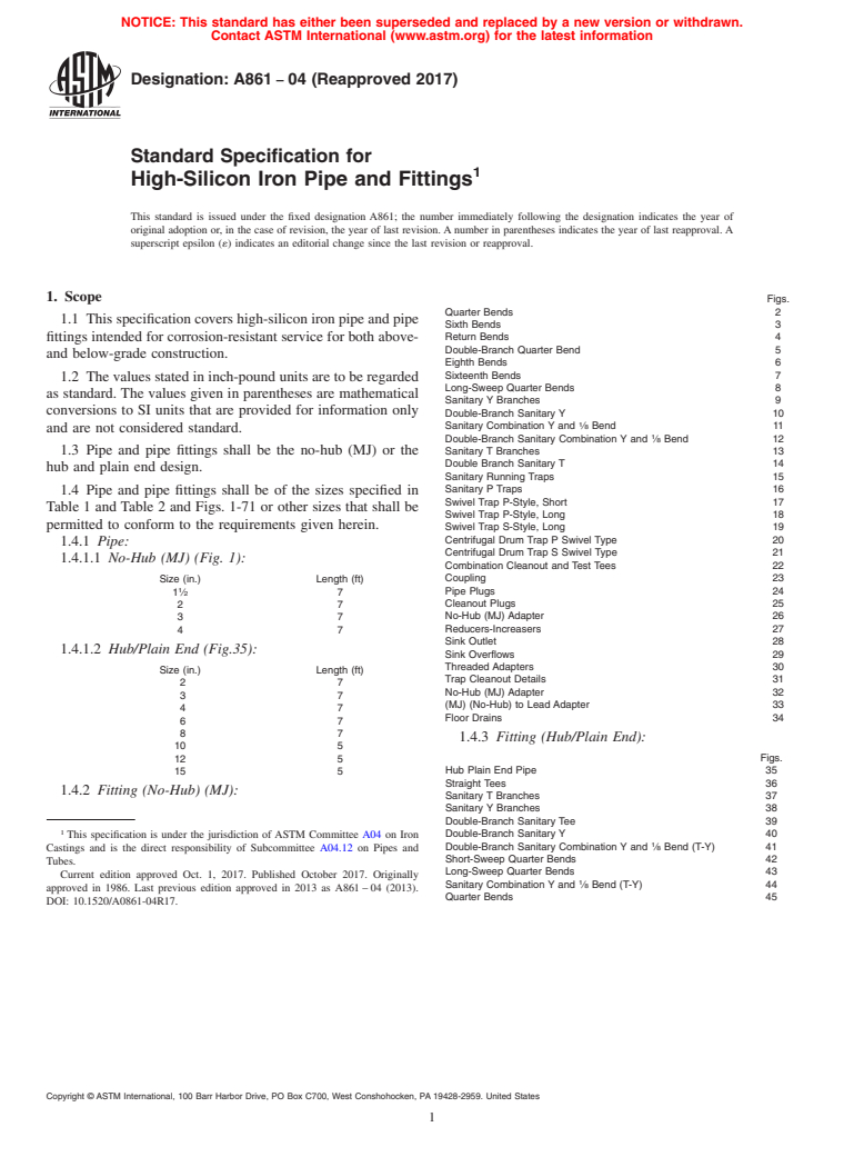
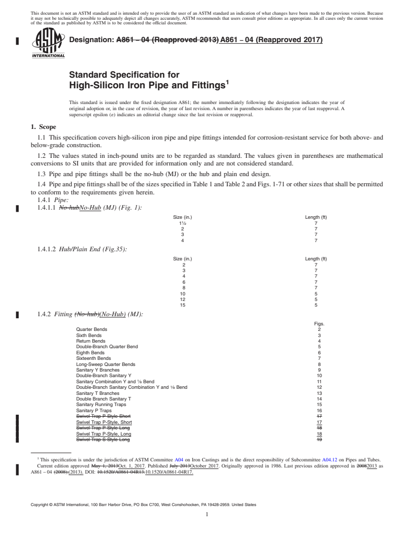
1.1 This specification covers high-silicon iron pipe and pipe fittings intended for corrosion-resistant service for both above- and below-grade construction.
1.2 The values stated in inch-pound units are to be regarded as standard. The values given in parentheses are mathematical conversions to SI units that are provided for information only and are not considered standard.
1.3 Pipe and pipe fittings shall be the no-hub (MJ) or the hub and plain end design.
1.4 Pipe and pipe fittings shall be of the sizes specified in Table 1 and Table 2 and Figs. 1-71 or other sizes that shall be permitted to conform to the requirements given herein.
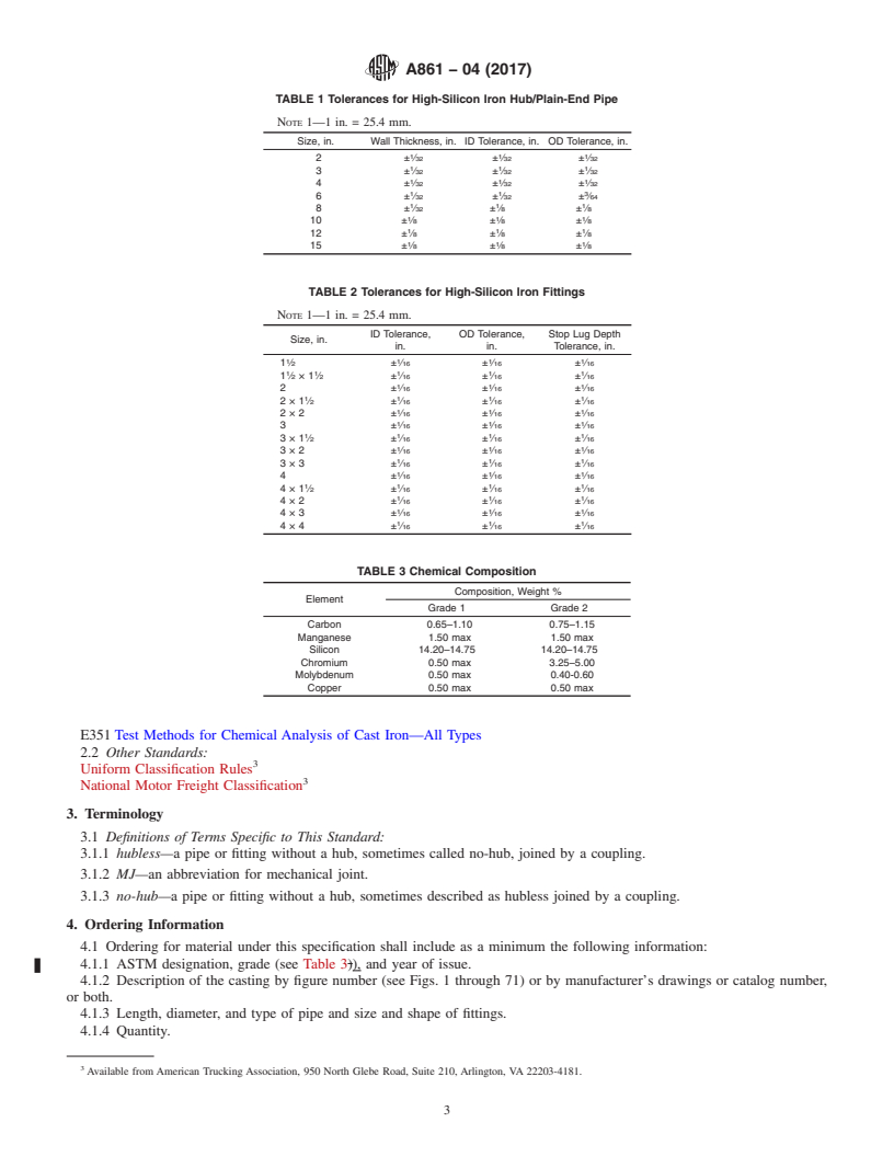
TABLE 1 Tolerances for High-Silicon Iron Hub/Plain-End Pipe
Note 1: 1 in. = 25.4 mm.
Size, in.
Wall Thickness, in.
ID Tolerance, in.
OD Tolerance, in.
2
±1/32
±1/32
±1/32
3
±1/32
±1/32
±1/32
4
±1/32
±1/32
±1/32
6
±1/32
±1/32
±3/64
8
±1/32
±1/8
±1/8
10
±1/8
±1/8
±1/8
12
±1/8
±1/8
±1/8
15
±1/8
±1/8
±1/8
TABLE 2 Tolerances for High-Silicon Iron Fittings
Note 1: 1 in. = 25.4 mm.
Size, in.
ID Tolerance,
in.
OD Tolerance,
in.
Stop Lug Depth
Tolerance, in.
11/2
±1/16
±1/16
±1/16
11/2 × 11/2
±1/16
±1/16
±1/16
2
±1/16
±1/16
±1/16
2 × 11/2
±1/16
±1/16
±1/16
2 × 2
±1/16
±1/16
±1/16
3
±1/16
±1/16
±1/16
3 × 11/2
±1/16
±1/16
±1/16
3 × 2
±1/16
±1/16
±1/16
3 × 3
±1/16
±1/16
±1/16
4
±1/16
±1/16
±1/16
4 × 11/2
±1/16
±1/16
±1/16
4 × 2
±1/16
±1/16
±1/16
4 × 3
±1/16
±1/16
±1/16
4 × 4
±1/16
±1/16
±1/16
TABLE 3 Chemical Composition
Element
Composition, Weight %
Grade 1
Grade 2
Carbon
0.65–1.10
0.75–1.15
Manganese
1.50 max
1.50 max
Silicon
14.20–14.75
14.20–14.75
Chromium
0.50 max
3.25–5.00
Molybdenum
0.50 max
0.40-0.60
Copper
0.50 max
0.50 max
FIG. 1 No-Hub Pipe (MJ)
Size, in.
J, in.
F, in.
t, in.
11/2
23/16 (2.19)
84
5/16
2
211/16 (2.69)
84
5/16
3
349/64 (3.77)
84
5/16
4
449/64 (4.77)
84
5/16
Note 1: 1 in. = 25.4 mm.
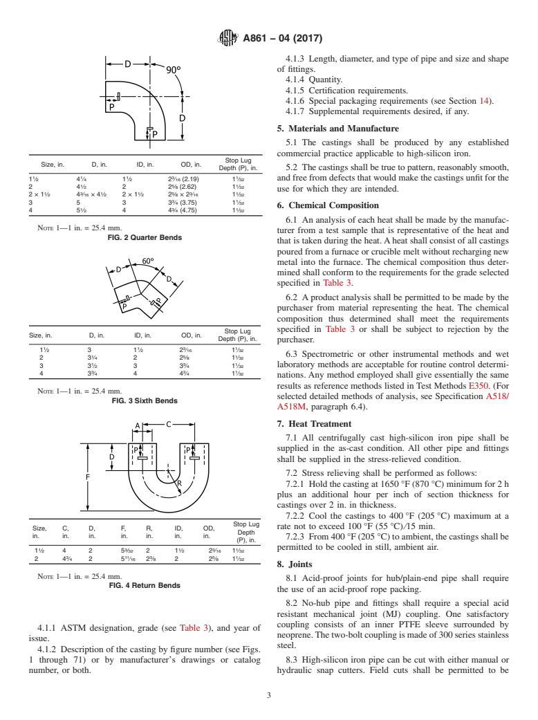
FIG. 2 Quarter Bends
Size, in.
D, in.
ID, in.
OD, in.
Stop Lug
Depth (P), in.
11/2
41/4
11/2
23/16 (2.19)
11/32
2
41/2
2
25/8 (2.62)
11/32
2 × 11/2
43/16 × 41/2
2 × 11/2
25/8 × 23/16
11/32
3
5
3
33/4 (3.75)
11/32
4
51/2
4
43/4 (4.75)
11/32
Note 1: 1 in. = 25.4 mm.
FIG. 3 Sixth Bends
Size, in.
D, in.
ID, in.
OD, in.
Stop Lug
Depth (P), in.
11/2
3
11/2
23/16
11/32
2
...
General Information
Buy Standard
Standards Content (Sample)
NOTICE: This standard has either been superseded and replaced by a new version or withdrawn.
Contact ASTM International (www.astm.org) for the latest information
Designation: A861 − 04 (Reapproved 2017)
Standard Specification for
High-Silicon Iron Pipe and Fittings
This standard is issued under the fixed designation A861; the number immediately following the designation indicates the year of
original adoption or, in the case of revision, the year of last revision. A number in parentheses indicates the year of last reapproval. A
superscript epsilon (´) indicates an editorial change since the last revision or reapproval.
1. Scope
Figs.
Quarter Bends 2
1.1 This specification covers high-silicon iron pipe and pipe
Sixth Bends 3
fittings intended for corrosion-resistant service for both above- Return Bends 4
Double-Branch Quarter Bend 5
and below-grade construction.
Eighth Bends 6
Sixteenth Bends 7
1.2 The values stated in inch-pound units are to be regarded
Long-Sweep Quarter Bends 8
as standard. The values given in parentheses are mathematical
Sanitary Y Branches 9
conversions to SI units that are provided for information only
Double-Branch Sanitary Y 10
Sanitary Combination Y and ⁄8 Bend 11
and are not considered standard.
Double-Branch Sanitary Combination Y and ⁄8 Bend 12
1.3 Pipe and pipe fittings shall be the no-hub (MJ) or the Sanitary T Branches 13
Double Branch Sanitary T 14
hub and plain end design.
Sanitary Running Traps 15
Sanitary P Traps 16
1.4 Pipe and pipe fittings shall be of the sizes specified in
Swivel Trap P-Style, Short 17
Table 1 and Table 2 and Figs. 1-71 or other sizes that shall be
Swivel Trap P-Style, Long 18
permitted to conform to the requirements given herein.
Swivel Trap S-Style, Long 19
Centrifugal Drum Trap P Swivel Type 20
1.4.1 Pipe:
Centrifugal Drum Trap S Swivel Type 21
1.4.1.1 No-Hub (MJ) (Fig. 1):
Combination Cleanout and Test Tees 22
Coupling 23
Size (in.) Length (ft)
Pipe Plugs 24
1 ⁄2 7
Cleanout Plugs 25
2 7
3 7 No-Hub (MJ) Adapter 26
Reducers-Increasers 27
4 7
Sink Outlet 28
1.4.1.2 Hub/Plain End (Fig.35):
Sink Overflows 29
Threaded Adapters 30
Size (in.) Length (ft)
Trap Cleanout Details 31
2 7
No-Hub (MJ) Adapter 32
3 7
(MJ) (No-Hub) to Lead Adapter 33
4 7
Floor Drains 34
6 7
8 7
1.4.3 Fitting (Hub/Plain End):
10 5
Figs.
12 5
15 5 Hub Plain End Pipe 35
Straight Tees 36
1.4.2 Fitting (No-Hub) (MJ):
Sanitary T Branches 37
Sanitary Y Branches 38
Double-Branch Sanitary Tee 39
This specification is under the jurisdiction of ASTM Committee A04 on Iron Double-Branch Sanitary Y 40
Double-Branch Sanitary Combination Y and ⁄8 Bend (T-Y) 41
Castings and is the direct responsibility of Subcommittee A04.12 on Pipes and
Short-Sweep Quarter Bends 42
Tubes.
Long-Sweep Quarter Bends 43
Current edition approved Oct. 1, 2017. Published October 2017. Originally
Sanitary Combination Y and ⁄8 Bend (T-Y) 44
approved in 1986. Last previous edition approved in 2013 as A861 – 04 (2013).
Quarter Bends 45
DOI: 10.1520/A0861-04R17.
Copyright © ASTM International, 100 Barr Harbor Drive, PO Box C700, West Conshohocken, PA 19428-2959. United States
A861 − 04 (2017)
TABLE 2 Tolerances for High-Silicon Iron Fittings
Sixth Bends 46
Eighth Bends 47
NOTE 1—1 in. = 25.4 mm.
Sixteenth Bends 48
Sanitary Increasers 49 ID Tolerance, OD Tolerance, Stop Lug Depth
Size, in.
Hub Strainers 50 in. in. Tolerance, in.
Sanitary Reducers 51
1 1 1 1
1 ⁄2 ± ⁄16 ± ⁄16 ± ⁄16
Double Hubs 52
1 1 1 1 1
1 ⁄2 × 1 ⁄2 ± ⁄16 ± ⁄16 ± ⁄16
Pipe Plugs 53
1 1 1
2 ± ⁄16 ± ⁄16 ± ⁄16
Cleanout Plugs 54
1 1 1 1
2 × 1 ⁄2 ± ⁄16 ± ⁄16 ± ⁄16
Adapter – Plain end to Split Flange 55
1 1 1
2 × 2 ± ⁄16 ± ⁄16 ± ⁄16
Adapter – Hub to-Split Flange 56
1 1 1
3 ± ⁄16 ± ⁄16 ± ⁄16
Combination Cleanout and Test Tees 57
1 1 1 1
3 × 1 ⁄2 ± ⁄16 ± ⁄16 ± ⁄16
Insertable Joints 58
1 1 1
3 × 2 ± ⁄16 ± ⁄16 ± ⁄16
Backwater Valves 59
1 1 1
3 × 3 ± ⁄16 ± ⁄16 ± ⁄16
Sanitary P Traps 60
1 1 1
4 ± ⁄16 ± ⁄16 ± ⁄16
Sanitary S Traps 61
1 1 1 1
4 × 1 ⁄2 ± ⁄16 ± ⁄16 ± ⁄16
Sanitary Running Traps 62
1 1 1
4 × 2 ± ⁄16 ± ⁄16 ± ⁄16
Floor Drains 63, 64, 65
1 1 1
4 × 3 ± ⁄16 ± ⁄16 ± ⁄16
Floor Drains 66
1 1 1
4 × 4 ± ⁄16 ± ⁄16 ± ⁄16
Floor Drains/Installation – Funnel Attachment 67, 68
Overflow 69
Sink Outlet 70
Detailed Cross Section of Cleanout 71
TABLE 3 Chemical Composition
Chemical Composition Table 3
Composition, Weight %
Transverse Bend Test Minimum Requirements Table S1.1
Element
Grade 1 Grade 2
1.5 This international standard was developed in accor-
Carbon 0.65–1.10 0.75–1.15
dance with internationally recognized principles on standard-
Manganese 1.50 max 1.50 max
ization established in the Decision on Principles for the
Silicon 14.20–14.75 14.20–14.75
Chromium 0.50 max 3.25–5.00
Development of International Standards, Guides and Recom-
Molybdenum 0.50 max 0.40-0.60
mendations issued by the World Trade Organization Technical
Copper 0.50 max 0.50 max
Barriers to Trade (TBT) Committee.
2. Referenced Documents
2.1 ASTM Standards:
A518/A518M Specification for Corrosion-Resistant High-
Silicon Iron Castings
E350 Test Methods for Chemical Analysis of Carbon Steel,
Low-Alloy Steel, Silicon Electrical Steel, Ingot Iron, and
Wrought Iron
E351 Test Methods for Chemical Analysis of Cast Iron—All
Types
2.2 Other Standards:
Uniform Classification Rules
Size, in. J, in. F, in. t, in.
National Motor Freight Classification
1 3 5
1 ⁄2 2 ⁄16 (2.19) 84 ⁄16
11 5
2 2 ⁄16 (2.69) 84 ⁄16
49 5
3 3 ⁄64 (3.77) 84 ⁄16
49 5
4 4 ⁄64 (4.77) 84 ⁄16
NOTE 1—1 in. = 25.4 mm.
For referenced ASTM standards, visit the ASTM website, www.astm.org, or
contact ASTM Customer Service at service@astm.org. For Annual Book of ASTM FIG. 1 No-Hub Pipe (MJ)
Standards volume information, refer to the standard’s Document Summary page on
the ASTM website.
Available from American Trucking Association, 950 North Glebe Road, Suite
210, Arlington, VA 22203-4181.
3. Terminology
3.1 Definitions of Terms Specific to This Standard:
TABLE 1 Tolerances for High-Silicon Iron Hub/Plain-End Pipe
3.1.1 hubless—a pipe or fitting without a hub, sometimes
NOTE 1—1 in. = 25.4 mm.
called no-hub, joined by a coupling.
Size, in. Wall Thickness, in. ID Tolerance, in. OD Tolerance, in.
3.1.2 MJ—an abbreviation for mechanical joint.
1 1 1
2 ± ⁄32 ± ⁄32 ± ⁄32
1 1 1
3.1.3 no-hub—a pipe or fitting without a hub, sometimes
3 ± ⁄32 ± ⁄32 ± ⁄32
1 1 1
4 ± ⁄32 ± ⁄32 ± ⁄32
described as hubless joined by a coupling.
1 1 3
6 ± ⁄32 ± ⁄32 ± ⁄64
1 1 1
8 ± ⁄32 ± ⁄8 ± ⁄8
1 1 1
4. Ordering Information
10 ± ⁄8 ± ⁄8 ± ⁄8
1 1 1
12 ± ⁄8 ± ⁄8 ± ⁄8
4.1 Ordering for material under this specification shall
1 1 1
15 ± ⁄8 ± ⁄8 ± ⁄8
include as a minimum the following information:
A861 − 04 (2017)
4.1.3 Length, diameter, and type of pipe and size and shape
of fittings.
4.1.4 Quantity.
4.1.5 Certification requirements.
4.1.6 Special packaging requirements (see Section 14).
4.1.7 Supplemental requirements desired, if any.
5. Materials and Manufacture
5.1 The castings shall be produced by any established
commercial practice applicable to high-silicon iron.
Stop Lug
Size, in. D, in. ID, in. OD, in.
Depth (P), in. 5.2 The castings shall be true to pattern, reasonably smooth,
1 1 1 3 1
and free from defects that would make the castings unfit for the
1 ⁄2 4 ⁄4 1 ⁄2 2 ⁄16 (2.19) 1 ⁄32
1 5 1
2 4 ⁄2 2 2 ⁄8 (2.62) 1 ⁄32
use for which they are intended.
1 3 1 1 5 3 1
2 × 1 ⁄2 4 ⁄16 × 4 ⁄2 2 × 1 ⁄2 2 ⁄8 × 2 ⁄16 1 ⁄32
3 1
3 5 3 3 ⁄4 (3.75) 1 ⁄32
6. Chemical Composition
1 3 1
4 5 ⁄2 4 4 ⁄4 (4.75) 1 ⁄32
6.1 An analysis of each heat shall be made by the manufac-
NOTE 1—1 in. = 25.4 mm.
turer from a test sample that is representative of the heat and
FIG. 2 Quarter Bends
that is taken during the heat. A heat shall consist of all castings
poured from a furnace or crucible melt without recharging new
metal into the furnace. The chemical composition thus deter-
mined shall conform to the requirements for the grade selected
specified in Table 3.
6.2 A product analysis shall be permitted to be made by the
purchaser from material representing the heat. The chemical
composition thus determined shall meet the requirements
specified in Table 3 or shall be subject to rejection by the
Stop Lug
Size, in. D, in. ID, in. OD, in.
Depth (P), in.
purchaser.
1 1 3 1
1 ⁄2 3 1 ⁄2 2 ⁄16 1 ⁄32
6.3 Spectrometric or other instrumental methods and wet
1 5 1
2 3 ⁄4 2 2 ⁄8 1 ⁄32
1 3 1
3 3 ⁄2 3 3 ⁄4 1 ⁄32 laboratory methods are acceptable for routine control determi-
3 3 1
4 3 ⁄4 4 4 ⁄4 1 ⁄32
nations. Any method employed shall give essentially the same
results as reference methods listed in Test Methods E350. (For
NOTE 1—1 in. = 25.4 mm.
selected detailed methods of analysis, see Specification A518/
FIG. 3 Sixth Bends
A518M, paragraph 6.4).
7. Heat Treatment
7.1 All centrifugally cast high-silicon iron pipe shall be
supplied in the as-cast condition. All other pipe and fittings
shall be supplied in the stress-relieved condition.
7.2 Stress relieving shall be performed as follows:
7.2.1 Hold the casting at 1650 °F (870 °C) minimum for 2 h
plus an additional hour per inch of section thickness for
castings over 2 in. in thickness.
7.2.2 Cool the castings to 400 °F (205 °C) maximum at a
Stop Lug
rate not to exceed 100 °F (55 °C) ⁄15 min.
Size, C, D, F, R, ID, OD,
Depth
in. in. in. in. in. in. in.
7.2.3 From 400 °F (205 °C) to ambient, the castings shall be
(P), in.
permitted to be cooled in still, ambient air.
1 3 1 3 1
1 ⁄2 4 2 5 ⁄32 2 1 ⁄2 2 ⁄16 1 ⁄32
3 11 3 5 1
2 4 ⁄4 2 5 ⁄16 2 ⁄8 2 2 ⁄8 1 ⁄32
8. Joints
NOTE 1—1 in. = 25.4 mm.
8.1 Acid-proof joints for hub/plain-end pipe shall require
FIG. 4 Return Bends
the use of an acid-proof rope packing.
8.2 No-hub pipe and fittings shall require a special acid
resistant mechanical joint (MJ) coupling. One satisfactory
coupling consists of an inner PTFE sleeve surrounded by
4.1.1 ASTM designation, grade (see Table 3), and year of
neoprene. The two-bolt coupling is made of 300 series stainless
issue.
steel.
4.1.2 Description of the casting by figure number (see Figs.
1 through 71) or by manufacturer’s drawings or catalog 8.3 High-silicon iron pipe can be cut with either manual or
number, or both. hydraulic snap cutters. Field cuts shall be permitted to be
A861 − 04 (2017)
Stop Lug
Size, D, E, ID, OD,
Depth (P),
in. in. in. in. in.
in.
1 7 3 1 3 1
1 ⁄2 3 ⁄8 3 ⁄4 1 ⁄2 2 ⁄16 1 ⁄32
NOTE 1—1 in. = 25.4 mm.
FIG. 5 Double-Branch Quarter Bend
Size, D, ID, OD, Stop Lug Depth
in. in. in. in. (P), in.
1 1 1 3 1
1 ⁄2 2 ⁄2 1 ⁄2 2 ⁄16 1 ⁄32
3 5 1
2 2 ⁄4 2 2 ⁄8 1 ⁄32
3 1
3 3 3 3 ⁄4 1 ⁄32
1 3 1
4 3 ⁄4 4 4 ⁄4 1 ⁄32
NOTE 1—1 in. = 25.4 mm.
FIG. 6 Eight Bends
Size, D, ID, OD, Stop Lug Depth
in. in. in. in. (P), in.
1 1 3 1
1 ⁄2 2 1 ⁄2 2 ⁄16 1 ⁄32
1 5 1
2 2 ⁄8 2 2 ⁄8 1 ⁄32
1 3 1
3 2 ⁄4 3 3 ⁄4 1 ⁄32
3 3 1
4 2 ⁄8 4 4 ⁄4 1 ⁄32
NOTE 1—1 in. = 25.4 mm.
FIG. 7 Sixteenth Bends
readily used with mechanical joint couplings to provide ac- 9.1.1 Hub/plain-end pipe shall have a hub at one end and a
ceptable leak-proof joints.
plain end at the other and shall be cast in one piece (see Fig.
35).
9. Dimensions and Permissible Variations
9.1.2 Individual length of hub/plain-end pipe shall be either
9.1 Pipe: 7 or 5 ft nominal laying lengths as shown in Fig. 35.
A861 − 04 (2017)
FIG. 8 Long-Sweep Quarter Bends
Stop Lug
Size, D, F, G, ID, OD,
Depth (P),
in. in. in. in. in in.
in.
1 1 5 1 7 1 1 3 3 1
⁄2 × 1 ⁄2 4 ⁄8 6 ⁄2 1 ⁄8 1 ⁄2 × 1 ⁄2 2 ⁄16 × 2 ⁄16 1 ⁄32
1 7 1 5 1 5 3 1
2 × 1 ⁄2 4 ⁄8 6 ⁄2 1 ⁄8 2 × 1 ⁄2 2 ⁄8 × 2 ⁄16 1 ⁄32
5 3 5 5 1
2 × 2 4 ⁄8 6 ⁄8 2 2 × 2 2 ⁄8 × 2 ⁄8 1 ⁄32
1 5 1 1 1 3 3 1
3 × 1 ⁄2 5 ⁄8 6 ⁄2 1 ⁄4 3 × 1 ⁄2 3 ⁄4 × 2 ⁄16 1 ⁄32
7 1 1 3 5 1
3 × 2 5 ⁄8 7 ⁄8 1 ⁄2 3 × 2 3 ⁄4 × 2 ⁄8 1 ⁄32
3 5 1 3 3 1
3 × 3 6 ⁄8 8 ⁄8 2 ⁄4 3 × 3 3 ⁄4 × 3 ⁄4 1 ⁄32
1 5 1 3 1 3 3 1
4 × 1 ⁄2 6 ⁄8 7 ⁄2 1 ⁄8 4 × 1 ⁄2 4 ⁄4 × 2 ⁄16 1 ⁄32
5 1 3 3 5 1
4 × 2 6 ⁄8 7 ⁄2 1 ⁄8 4 × 2 4 ⁄4 × 2 ⁄8 1 ⁄32
1 3 3 3 3 1
4 × 3 7 ⁄8 8 ⁄4 1 ⁄4 4 × 3 4 ⁄4 × 3 ⁄4 1 ⁄32
5 1 5 3 3 1
4 × 4 7 ⁄8 10 ⁄4 2 ⁄8 4 × 4 4 ⁄4 × 4 ⁄4 1 ⁄32
NOTE 1—1 in. = 25.4 mm.
FIG. 9 Sanitary Y Branches
9.1.3 Any deflections in the barrel of a single length of pipe specified herein. All tests and inspection with the exception of
shall not exceed ⁄16 in. product analysis shall be made at the place of manufacture
9.1.4 No-hub pipe shall be cast in a single piece and unless otherwise agreed upon.
conform to nominal dimensions shown in Fig. 1.
10.2 Inspection and Test by the Purchaser—The manufac-
9.1.5 No dimension of hub/plain-end pipe shall exceed the
turer shall afford the purchaser’s inspector all reasonable
tolerances specified in Table 1.
facilities necessary to satisfy that the material is being pro-
9.2 Fittings—All fittings shall conform to the nominal duced and furnished in accordance with this specification.
dimensions specified in applicable figures and be within the Foundry inspection by the purchaser shall not interfere unnec-
tolerances specified in Table 2 for fittings listed in Figs. 2 essarily with the manufacturer’s operations.
through 34 or in Table 1 for fittings listed in Figs. 36 through
11. Rejection and Rehearing
39.
11.1 Material that shows unacceptable discontinuities as
10. Inspection
determined by the acceptance standards specified in the order,
10.1 Inspection and Test by the Manufacturer—Pipe and subsequent to its acceptance at the manufacturer’s works, shall
fittings shall be inspected by the manufacturer prior to ship- be rejected and the manufacturer shall be notified within 30
ment. Inspection by the manufacturer shall include all tests as days unless otherwise agreed upon.
A861 − 04 (2017)
Size, D, F, G, ID, OD, Stop Lug
Depth (P),
in. in. in. in. in. in.
in.
1 1 5 1 7 1 1 3 3 1
1 ⁄2 × 1 ⁄2 4 ⁄8 6 ⁄2 1 ⁄8 1 ⁄2 × 1 ⁄2 2 ⁄16 × 2 ⁄16 1 ⁄32
1 7 1 5 1 5 3 1
2 × 1 ⁄2 4 ⁄8 6 ⁄2 1 ⁄8 2 × 1 ⁄2 2 ⁄8 × 2 ⁄16 1 ⁄32
5 3 5 5 1
2 × 2 4 ⁄8 6 ⁄8 2 2 × 2 2 ⁄8 × 2 ⁄8 1 ⁄32
1 5 1 1 1 3 3 1
3 × 1 ⁄2 5 ⁄8 6 ⁄2 1 ⁄4 3 × 1 ⁄2 3 ⁄4 × 2 ⁄16 1 ⁄32
7 1 1 3 5 1
3 × 2 5 ⁄8 7 ⁄8 1 ⁄2 3 × 2 3 ⁄4 × 2 ⁄8 1 ⁄32
3 5 1 3 3 1
3 × 3 6 ⁄8 8 ⁄8 2 ⁄4 3 × 3 3 ⁄4 × 3 ⁄4 1 ⁄32
5 1 3 3 5 1
4 × 2 6 ⁄8 7 ⁄2 1 ⁄8 4 × 2 4 ⁄4 × 2 ⁄8 1 ⁄32
1 3 3 3 3 1
4 × 3 7 ⁄8 8 ⁄4 1 ⁄4 4 × 3 4 ⁄4 × 3 ⁄4 1 ⁄32
5 1 5 3 3 1
4 × 4 7 ⁄8 10 ⁄4 2 ⁄8 4 × 4 4 ⁄4 × 4 ⁄4 1 ⁄32
NOTE 1—1 in. = 25.4 mm.
FIG. 10 Double-Branch Sanitary Y
Size, D, E, F, G, ID, OD, Stop Lug
in. in. in. in. in. in. in. Depth
(P), in.
1 1 3 3 1 7 1 1 3 3 1
1 ⁄2 × 1 ⁄2 4 ⁄4 5 ⁄8 6 ⁄2 1 ⁄8 ⁄2 × 1 ⁄2 2 ⁄16 × 2 ⁄16 1 ⁄32
1 3 3 1 5 1 5 3 1
2 × 1 ⁄2 4 ⁄4 5 ⁄4 6 ⁄2 1 ⁄8 2 × 1 ⁄2 2 ⁄8 × 2 ⁄16 1 ⁄32
7 5 7 5 5 1
2 × 2 5 5 ⁄8 6 ⁄8 1 ⁄8 2 × 2 2 ⁄8 × 2 ⁄8 1 ⁄32
1 1 1 5 1 3 3 1
3 × 1 ⁄2 4 5 ⁄4 6 ⁄2 1 ⁄8 3 × 1 ⁄2 3 ⁄4 × 2 ⁄16 1 ⁄32
1 1 1 3 5 1
3 × 2 5 6 ⁄4 7 ⁄8 1 ⁄2 3 × 2 3 ⁄4 × 2 ⁄8 1 ⁄32
1 1 1 3 3 1
3 × 3 6 ⁄4 7 8 ⁄2 2 ⁄4 3 × 3 3 ⁄4 × 3 ⁄4 1 ⁄32
1 5 1 5 3 1 3
...
This document is not an ASTM standard and is intended only to provide the user of an ASTM standard an indication of what changes have been made to the previous version. Because
it may not be technically possible to adequately depict all changes accurately, ASTM recommends that users consult prior editions as appropriate. In all cases only the current version
of the standard as published by ASTM is to be considered the official document.
Designation: A861 − 04 (Reapproved 2013) A861 − 04 (Reapproved 2017)
Standard Specification for
High-Silicon Iron Pipe and Fittings
This standard is issued under the fixed designation A861; the number immediately following the designation indicates the year of
original adoption or, in the case of revision, the year of last revision. A number in parentheses indicates the year of last reapproval. A
superscript epsilon (´) indicates an editorial change since the last revision or reapproval.
1. Scope
1.1 This specification covers high-silicon iron pipe and pipe fittings intended for corrosion-resistant service for both above- and
below-grade construction.
1.2 The values stated in inch-pound units are to be regarded as standard. The values given in parentheses are mathematical
conversions to SI units that are provided for information only and are not considered standard.
1.3 Pipe and pipe fittings shall be the no-hub (MJ) or the hub and plain end design.
1.4 Pipe and pipe fittings shall be of the sizes specified in Table 1 and Table 2 and Figs. 1-71 or other sizes that shall be permitted
to conform to the requirements given herein.
1.4.1 Pipe:
1.4.1.1 No-hubNo-Hub (MJ) (Fig. 1):
Size (in.) Length (ft)
1 ⁄2 7
2 7
3 7
4 7
1.4.1.2 Hub/Plain End (Fig.35):
Size (in.) Length (ft)
2 7
3 7
4 7
6 7
8 7
10 5
12 5
15 5
1.4.2 Fitting (No-hub)(No-Hub) (MJ):
Figs.
Quarter Bends 2
Sixth Bends 3
Return Bends 4
Double-Branch Quarter Bend 5
Eighth Bends 6
Sixteenth Bends 7
Long-Sweep Quarter Bends 8
Sanitary Y Branches 9
Double-Branch Sanitary Y 10
Sanitary Combination Y and ⁄8 Bend 11
Double-Branch Sanitary Combination Y and ⁄8 Bend 12
Sanitary T Branches 13
Double Branch Sanitary T 14
Sanitary Running Traps 15
Sanitary P Traps 16
Swivel Trap P-Style Short 17
Swivel Trap P-Style, Short 17
Swivel Trap P-Style Long 18
Swivel Trap P-Style, Long 18
Swivel Trap S-Style Long 19
This specification is under the jurisdiction of ASTM Committee A04 on Iron Castings and is the direct responsibility of Subcommittee A04.12 on Pipes and Tubes.
Current edition approved May 1, 2013Oct. 1, 2017. Published July 2013October 2017. Originally approved in 1986. Last previous edition approved in 20082013 as
A861 – 04 (2008).(2013). DOI: 10.1520/A0861-04R13.10.1520/A0861-04R17.
Copyright © ASTM International, 100 Barr Harbor Drive, PO Box C700, West Conshohocken, PA 19428-2959. United States
A861 − 04 (2017)
Swivel Trap S-Style, Long 19
Centrifugal Drum Trap P Swivel Type 20
Centrifugal Drum Trap S Swivel Type 21
Combination Cleanout and Test Tees 22
Coupling 23
Pipe Plugs 24
Cleanout Plugs 25
No-hub (MJ) Adapter 26
No-Hub (MJ) Adapter 26
Reducers—Increasers 27
Reducers-Increasers 27
Sink Outlet 28
Sink Overflows 29
Threaded Adapters 30
Trap Cleanout Details 31
No-hub (MJ) Adapter 32
No-Hub (MJ) Adapter 32
(MJ) (No-hub) to Lead Adapter 33
(MJ) (No-Hub) to Lead Adapter 33
Floor Drains 34
1.4.3 Fitting (Hub/Plain End):
Figs.
Hub Plain End Pipe 35
Straight Tees 36
Sanitary T Branches 37
Sanitary Y Branches 38
Double-Branch Sanitary Tee 39
Double-Branch Sanitary Y 40
Double-Branch Sanitary Combination Y and ⁄8 Bend (T-Y) 41
Short-Sweep Quarter Bends 42
Long-Sweep Quarter Bends 43
Sanitary Combination Y and ⁄8 Bend (T-Y) 44
Quarter Bends 45
Sixth Bends 46
Eighth Bends 47
Sixteenth Bends 48
Sanitary Increasers 49
Hub Strainers 50
Sanitary Reducers 51
Double Hubs 52
Pipe Plugs 53
Cleanout Plugs 54
Adapter—Plain end to Split Flange 55
Adapter – Plain end to Split Flange 55
Adapter—Hub to-Split Flange 56
Adapter – Hub to-Split Flange 56
Combination Cleanout and Test Tees 57
Insertable Joints 58
Backwater Valves 59
Sanitary P Traps 60
Sanitary S Traps 61
Sanitary Running Traps 62
Floor Drains 63, 64, 65
Floor Drains 66
Floor Drains/Installation—Funnel Attachment 67, 68
Floor Drains/Installation – Funnel Attachment 67, 68
Overflow 69
Sink Outlet 70
Detailed Cross Section of Cleanout 71
Chemical Composition Table 3
Transverse Bend Test Minimum Requirements Table S1.1
1.5 This international standard was developed in accordance with internationally recognized principles on standardization
established in the Decision on Principles for the Development of International Standards, Guides and Recommendations issued
by the World Trade Organization Technical Barriers to Trade (TBT) Committee.
2. Referenced Documents
2.1 ASTM Standards:
A518/A518M Specification for Corrosion-Resistant High-Silicon Iron Castings
E350 Test Methods for Chemical Analysis of Carbon Steel, Low-Alloy Steel, Silicon Electrical Steel, Ingot Iron, and Wrought
Iron
For referenced ASTM standards, visit the ASTM website, www.astm.org, or contact ASTM Customer Service at service@astm.org. For Annual Book of ASTM Standards
volume information, refer to the standard’s Document Summary page on the ASTM website.
A861 − 04 (2017)
TABLE 1 Tolerances for High-Silicon Iron Hub/Plain-End Pipe
NOTE 1—1 in. = 25.4 mm.
Size, in. Wall Thickness, in. ID Tolerance, in. OD Tolerance, in.
1 1 1
2 ± ⁄32 ± ⁄32 ± ⁄32
1 1 1
3 ± ⁄32 ± ⁄32 ± ⁄32
1 1 1
4 ± ⁄32 ± ⁄32 ± ⁄32
1 1 3
6 ± ⁄32 ± ⁄32 ± ⁄64
1 1 1
8 ± ⁄32 ± ⁄8 ± ⁄8
1 1 1
10 ± ⁄8 ± ⁄8 ± ⁄8
1 1 1
12 ± ⁄8 ± ⁄8 ± ⁄8
1 1 1
15 ± ⁄8 ± ⁄8 ± ⁄8
TABLE 2 Tolerances for High-Silicon Iron Fittings
NOTE 1—1 in. = 25.4 mm.
ID Tolerance, OD Tolerance, Stop Lug Depth
Size, in.
in. in. Tolerance, in.
1 1 1 1
1 ⁄2 ± ⁄16 ± ⁄16 ± ⁄16
1 1 1 1 1
1 ⁄2 × 1 ⁄2 ± ⁄16 ± ⁄16 ± ⁄16
1 1 1
2 ± ⁄16 ± ⁄16 ± ⁄16
1 1 1 1
2 × 1 ⁄2 ± ⁄16 ± ⁄16 ± ⁄16
1 1 1
2 × 2 ± ⁄16 ± ⁄16 ± ⁄16
1 1 1
3 ± ⁄16 ± ⁄16 ± ⁄16
1 1 1 1
3 × 1 ⁄2 ± ⁄16 ± ⁄16 ± ⁄16
1 1 1
3 × 2 ± ⁄16 ± ⁄16 ± ⁄16
1 1 1
3 × 3 ± ⁄16 ± ⁄16 ± ⁄16
1 1 1
4 ± ⁄16 ± ⁄16 ± ⁄16
1 1 1 1
4 × 1 ⁄2 ± ⁄16 ± ⁄16 ± ⁄16
1 1 1
4 × 2 ± ⁄16 ± ⁄16 ± ⁄16
1 1 1
4 × 3 ± ⁄16 ± ⁄16 ± ⁄16
1 1 1
4 × 4 ± ⁄16 ± ⁄16 ± ⁄16
TABLE 3 Chemical Composition
Composition, Weight %
Element
Grade 1 Grade 2
Carbon 0.65–1.10 0.75–1.15
Manganese 1.50 max 1.50 max
Silicon 14.20–14.75 14.20–14.75
Chromium 0.50 max 3.25–5.00
Molybdenum 0.50 max 0.40-0.60
Copper 0.50 max 0.50 max
E351 Test Methods for Chemical Analysis of Cast Iron—All Types
2.2 Other Standards:
Uniform Classification Rules
National Motor Freight Classification
3. Terminology
3.1 Definitions of Terms Specific to This Standard:
3.1.1 hubless—a pipe or fitting without a hub, sometimes called no-hub, joined by a coupling.
3.1.2 MJ—an abbreviation for mechanical joint.
3.1.3 no-hub—a pipe or fitting without a hub, sometimes described as hubless joined by a coupling.
4. Ordering Information
4.1 Ordering for material under this specification shall include as a minimum the following information:
4.1.1 ASTM designation, grade (see Table 3)), and year of issue.
4.1.2 Description of the casting by figure number (see Figs. 1 through 71) or by manufacturer’s drawings or catalog number,
or both.
4.1.3 Length, diameter, and type of pipe and size and shape of fittings.
4.1.4 Quantity.
Available from American Trucking Association, 950 North Glebe Road, Suite 210, Arlington, VA 22203-4181.
A861 − 04 (2017)
Size, in. J, in. F, in. t, in.
1 3 5
1 ⁄2 2 ⁄16 (2.19) 84 ⁄16
11 5
2 2 ⁄16 (2.69) 84 ⁄16
49 5
3 3 ⁄64 (3.77) 84 ⁄16
49 5
4 4 ⁄64 (4.77) 84 ⁄16
NOTE 1—1 in. = 25.4 mm.
FIG. 1 No-Hub Pipe (MJ)
Stop Lug
Size, in. D, in. ID, in. OD, in.
Depth (P), in.
1 1 1 3 1
1 ⁄2 4 ⁄4 1 ⁄2 2 ⁄16 (2.19) 1 ⁄32
1 5 1
2 4 ⁄2 2 2 ⁄8 (2.62) 1 ⁄32
1 3 1 1 5 3 1
2 × 1 ⁄2 4 ⁄16 × 4 ⁄2 2 × 1 ⁄2 2 ⁄8 × 2 ⁄16 1 ⁄32
3 1
3 5 3 3 ⁄4 (3.75) 1 ⁄32
1 3 1
4 5 ⁄2 4 4 ⁄4 (4.75) 1 ⁄32
NOTE 1—1 in. = 25.4 mm.
FIG. 2 Quarter Bends
Stop Lug
Size, in. D, in. ID, in. OD, in.
Depth (P), in.
1 1 3 1
1 ⁄2 3 1 ⁄2 2 ⁄16 1 ⁄32
1 5 1
2 3 ⁄4 2 2 ⁄8 1 ⁄32
1 3 1
3 3 ⁄2 3 3 ⁄4 1 ⁄32
3 3 1
4 3 ⁄4 4 4 ⁄4 1 ⁄32
NOTE 1—1 in. = 25.4 mm.
FIG. 3 Sixth Bends
4.1.5 Certification requirements.
4.1.6 Special packaging requirements (see Section 14).
4.1.7 Supplemental requirements desired, if any.
A861 − 04 (2017)
Stop Lug
Size, C, D, F, R, ID, OD,
Depth
in. in. in. in. in. in. in.
(P), in.
1 3 1 3 1
1 ⁄2 4 2 5 ⁄32 2 1 ⁄2 2 ⁄16 1 ⁄32
3 11 3 5 1
2 4 ⁄4 2 5 ⁄16 2 ⁄8 2 2 ⁄8 1 ⁄32
NOTE 1—1 in. = 25.4 mm.
FIG. 4 Return Bends
5. Materials and Manufacture
5.1 The castings shall be produced by any established commercial practice applicable to high-silicon iron.
5.2 The castings shall be true to pattern, reasonably smooth, and free from defects that would make the castings unfit for the
use for which they are intended.
6. Chemical Composition
6.1 An analysis of each heat shall be made by the manufacturer from a test sample that is representative of the heat and that
is taken during the heat. A heat shall consist of all castings poured from a furnace or crucible melt without recharging new metal
into the furnace. The chemical composition thus determined shall conform to the requirements for the grade selected specified in
Table 3.
6.2 A product analysis shall be permitted to be made by the purchaser from material representing the heat. The chemical
composition thus determined shall meet the requirements specified in Table 3 or shall be subject to rejection by the purchaser.
6.3 Spectrometric or other instrumental methods and wet laboratory methods are acceptable for routine control determinations.
Any method employed shall give essentially the same results as reference methods listed in Test Methods E350. (For selected
detailed methods of analysis, see Specification A518/A518M, paragraph 6.4).
7. Heat Treatment
7.1 All centrifugally cast high-silicon iron pipe shall be supplied in the as-cast condition. All other pipe and fittings shall be
supplied in the stress-relieved condition.
7.2 Stress relieving shall be performed as follows:
7.2.1 Hold the casting at 1650°F (870°C)1650 °F (870 °C) minimum for 2 h 2 h plus an additional hour per inch of section
thickness for castings over 2 in. in thickness.
7.2.2 Cool the castings to 400°F (205°C)400 °F (205 °C) maximum at a rate not to exceed 100°F (55°C)/15100 °F (55 °C) ⁄15
min.
7.2.3 From 400°F (205°C)400 °F (205 °C) to ambient, the castings shall be permitted to be cooled in still, ambient air.
8. Joints
8.1 Acid-proof joints for hub/plain-end pipe shall require the use of an acid-proof rope packing.
8.2 No-hub pipe and fittings shall require a special acid resistant mechanical joint (MJ) coupling. One satisfactory coupling
consists of an inner PTFE sleeve surrounded by neoprene. The two-bolt coupling is made of 300 series stainless steel.
8.3 High-silicon iron pipe can be cut with either manual or hydraulic snap cutters. Field cuts shall be permitted to be readily
used with mechanical joint couplings to provide acceptable leak-proof joints.
9. Dimensions and Permissible Variations
9.1 Pipe:
9.1.1 Hub/plain-end pipe shall have a hub at one end and a plain end at the other and shall be cast in one piece (see Fig. 35).
9.1.2 Individual length of hub/plain-end pipe shall be either 7 or 5 ft nominal laying lengths as shown in Fig. 35.
9.1.3 Any deflections in the barrel of a single length of pipe shall not exceed ⁄16 in.
A861 − 04 (2017)
Stop Lug
Size, D, E, ID, OD,
Depth (P),
in. in. in. in. in.
in.
1 7 3 1 3 1
1 ⁄2 3 ⁄8 3 ⁄4 1 ⁄2 2 ⁄16 1 ⁄32
NOTE 1—1 in. = 25.4 mm.
FIG. 5 Double-Branch Quarter Bend
Size, D, ID, OD, Stop Lug Depth
in. in. in. in. (P), in.
1 1 1 3 1
1 ⁄2 2 ⁄2 1 ⁄2 2 ⁄16 1 ⁄32
3 5 1
2 2 ⁄4 2 2 ⁄8 1 ⁄32
3 1
3 3 3 3 ⁄4 1 ⁄32
1 3 1
4 3 ⁄4 4 4 ⁄4 1 ⁄32
NOTE 1—1 in. = 25.4 mm.
FIG. 6 Eight Bends
Size, D, ID, OD, Stop Lug Depth
in. in. in. in. (P), in.
1 1 3 1
1 ⁄2 2 1 ⁄2 2 ⁄16 1 ⁄32
1 5 1
2 2 ⁄8 2 2 ⁄8 1 ⁄32
1 3 1
3 2 ⁄4 3 3 ⁄4 1 ⁄32
3 3 1
4 2 ⁄8 4 4 ⁄4 1 ⁄32
NOTE 1—1 in. = 25.4 mm.
FIG. 7 Sixteenth Bends
9.1.4 No-hub pipe shall be cast in a single piece and conform to nominal dimensions shown in Fig. 1.
9.1.5 No dimension of hub/plain-end pipe shall exceed the tolerances specified in Table 1.
9.2 Fittings—All fittings shall conform to the nominal dimensions specified in applicable figures and be within the tolerances
specified in Table 2 for fittings listed in Figs. 2 through 34 or in Table 1 for fittings listed in Figs. 36 through 39.
A861 − 04 (2017)
FIG. 8 Long-Sweep Quarter Bends
Stop Lug
Size, D, F, G, ID, OD,
Depth (P),
in. in. in. in. in in.
in.
1 1 5 1 7 1 1 3 3 1
⁄2 × 1 ⁄2 4 ⁄8 6 ⁄2 1 ⁄8 1 ⁄2 × 1 ⁄2 2 ⁄16 × 2 ⁄16 1 ⁄32
1 7 1 5 1 5 3 1
2 × 1 ⁄2 4 ⁄8 6 ⁄2 1 ⁄8 2 × 1 ⁄2 2 ⁄8 × 2 ⁄16 1 ⁄32
5 3 5 5 1
2 × 2 4 ⁄8 6 ⁄8 2 2 × 2 2 ⁄8 × 2 ⁄8 1 ⁄32
1 5 1 1 1 3 3 1
3 × 1 ⁄2 5 ⁄8 6 ⁄2 1 ⁄4 3 × 1 ⁄2 3 ⁄4 × 2 ⁄16 1 ⁄32
7 1 1 3 5 1
3 × 2 5 ⁄8 7 ⁄8 1 ⁄2 3 × 2 3 ⁄4 × 2 ⁄8 1 ⁄32
3 5 1 3 3 1
3 × 3 6 ⁄8 8 ⁄8 2 ⁄4 3 × 3 3 ⁄4 × 3 ⁄4 1 ⁄32
1 5 1 3 1 3 3 1
4 × 1 ⁄2 6 ⁄8 7 ⁄2 1 ⁄8 4 × 1 ⁄2 4 ⁄4 × 2 ⁄16 1 ⁄32
5 1 3 3 5 1
4 × 2 6 ⁄8 7 ⁄2 1 ⁄8 4 × 2 4 ⁄4 × 2 ⁄8 1 ⁄32
1 3 3 3 3 1
4 × 3 7 ⁄8 8 ⁄4 1 ⁄4 4 × 3 4 ⁄4 × 3 ⁄4 1 ⁄32
5 1 5 3 3 1
4 × 4 7 ⁄8 10 ⁄4 2 ⁄8 4 × 4 4 ⁄4 × 4 ⁄4 1 ⁄32
NOTE 1—1 in. = 25.4 mm.
FIG. 9 Sanitary Y Branches
10. Inspection
10.1 Inspection and Test by the Manufacturer—Pipe and fittings shall be inspected by the manufacturer prior to shipment.
Inspection by the manufacturer shall include all tests as specified herein. All tests and inspection with the exception of product
analysis shall be made at the place of manufacture unless otherwise agreed upon.
10.2 Inspection and Test by the Purchaser—The manufacturer shall afford the purchaser’s inspector all reasonable facilities
necessary to satisfy that the material is being produced and furnished in accordance with this specification. Foundry inspection by
the purchaser shall not interfere unnecessarily with the manufacturer’s operations.
11. Rejection and Rehearing
11.1 Material that shows unacceptable discontinuities as determined by the acceptance standards specified in the order,
subsequent to its acceptance at the manufacturer’s works, shall be rejected and the manufacturer shall be notified within 30 days
unless otherwise agreed upon.
12. Certification
12.1 Upon request of the purchaser, the manufacturer shall certify that his product conforms to the requirements of this
specification. The results of tests shall be furnished to the purchaser upon request as mutually agreed upon.
A861 − 04 (2017)
Size, D, F, G, ID, OD, Stop Lug
Depth (P),
in. in. in. in. in. in.
in.
1 1 5 1 7 1 1 3 3 1
1 ⁄2 × 1 ⁄2 4
...
Questions, Comments and Discussion
Ask us and Technical Secretary will try to provide an answer. You can facilitate discussion about the standard in here.