

SIST EN 302 617-1 V1.1.1:2009
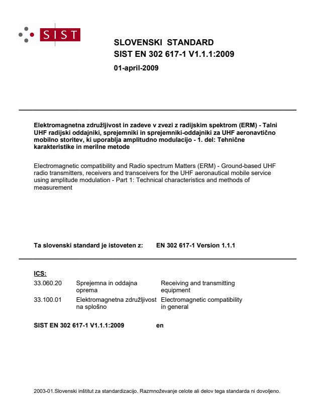
Electromagnetic compatibility and Radio spectrum Matters (ERM) - Ground-based UHF radio transmitters, receivers and transceivers for the UHF aeronautical mobile service using amplitude modulation - Part 1: Technical characteristics and methods of measurement
General Information
- Abstract
The present document states the minimum performance requirements for radio transmitters receivers and transceivers at ground-based aeronautical stations operating in the UHF band (225 MHz to 399,975 MHz) allocated to the aeronautical mobile service. The present document applies to DSB AM systems, with channel separations of 25 kHz intended for analogue speech. The scope of the present document is limited to ground base stations.
- Status
- Published
- Public Enquiry End Date
- 30-Apr-2008
- Publication Date
- 02-Mar-2009
- Technical Committee
- MOC - Mobile Communications
- Current Stage
- 6060 - National Implementation/Publication (Adopted Project)
- Start Date
- 17-Feb-2009
- Due Date
- 24-Apr-2009
- Completion Date
- 03-Mar-2009
Buy Documents
ETSI EN 302 617-1 V1.1.1 (2008-11) - Electromagnetic compatibility and Radio spectrum Matters (ERM); Ground-based UHF radio transmitters, receivers and transceivers for the UHF aeronautical mobile service using amplitude modulation; Part 1: Technical characteristics and methods of measurement
ETSI EN 302 617-1 V1.1.1 (2009-01) - Electromagnetic compatibility and Radio spectrum Matters (ERM); Ground-based UHF radio transmitters, receivers and transceivers for the UHF aeronautical mobile service using amplitude modulation; Part 1: Technical characteristics and methods of measurement

Overview
SIST EN 302 617-1 V1.1.1:2009 establishes the minimum technical and measurement requirements for ground-based UHF radio transmitters, receivers, and transceivers used in the aeronautical mobile service. This European standard, developed by the Slovenski inštitut za standardizacijo (SIST), applies exclusively to equipment operating within aeronautical stations in the UHF band 225 MHz to 399.975 MHz, using double side band (DSB) amplitude modulation (AM) with 25 kHz channel spacing for analogue speech communication.
Strict compliance with electromagnetic compatibility and radio spectrum management is crucial in the aviation sector. This document provides a comprehensive framework to ensure equipment interoperability, safety, and reliability within ground-based communication infrastructure.
Key Topics
The standard covers essential subject areas and performance criteria, including:
- Minimum Performance Requirements: Specifies expected baseline functioning for transmitters, receivers, and transceivers in UHF aeronautical base stations.
- Technical Characteristics: Covers amplitude modulation (AM) properties, channel spacing (25 kHz), and DSB transmission.
- Methods of Measurement: Outlines standard test set-ups and measurement procedures to verify compliance with performance and electromagnetic compatibility requirements.
- General Requirements: Includes controls and indicators, class of emission, warm-up conditions, and prevention of unauthorized parameter changes.
- Transmitter and Receiver Tests: Defines parameters such as frequency error, carrier power, modulation depth, adjacent channel power, sensitivity, harmonic distortion, noise, and more.
- Environmental Testing: Specifies test conditions under varying power sources, ambient temperature, and humidity to ensure reliable operation.
- Measurement Uncertainty: Addresses acceptable measurement uncertainty levels and interpretation of test results.
Applications
This standard is key to maintaining safe and effective ground-based aeronautical communication by ensuring:
- Interoperability: Compatible performance across UHF aeronautical mobile base stations, fostering seamless voice communication between air traffic control and aircraft.
- Safety: Reliable and interference-free transmission and reception within the critical aeronautical UHF band, minimizing risk from spurious emissions or equipment malfunction.
- Regulatory Compliance: Fulfilment of European and international requirements for equipment certification, supporting regulatory approval and market access in the aviation sector.
- Quality Assurance: Consistent manufacturing and maintenance of communication equipment in line with rigorous, standardized test protocols.
Typical users include equipment manufacturers, service providers, regulatory bodies, and maintenance organizations responsible for implementation, inspection, and certification of ground-based UHF radio systems at airports or other aeronautical facilities.
Related Standards
For comprehensive system design and compliance, refer to these related standards:
- ETSI EN 302 617-2: Harmonized EN covering essential requirements, complementing Part 1 by addressing regulatory directives.
- ITU-T Recommendation O.41: Provides guidance on equipment for circuit noise measurement relevant to radio communications.
- ETSI EN 300 113-1: Covers land mobile radio equipment characteristics and measurement methods, useful for comparison or interoperability in mixed environments.
- NATO STANAG 4205: Technical standards for single channel UHF radio equipment, particularly for military or defense applications.
By aligning with SIST EN 302 617-1 V1.1.1:2009, stakeholders ensure their ground-based UHF radio communication equipment for the aeronautical mobile service meets international expectations for performance, reliability, and electromagnetic compatibility.
Buy Documents
ETSI EN 302 617-1 V1.1.1 (2008-11) - Electromagnetic compatibility and Radio spectrum Matters (ERM); Ground-based UHF radio transmitters, receivers and transceivers for the UHF aeronautical mobile service using amplitude modulation; Part 1: Technical characteristics and methods of measurement
ETSI EN 302 617-1 V1.1.1 (2009-01) - Electromagnetic compatibility and Radio spectrum Matters (ERM); Ground-based UHF radio transmitters, receivers and transceivers for the UHF aeronautical mobile service using amplitude modulation; Part 1: Technical characteristics and methods of measurement
Get Certified
Connect with accredited certification bodies for this standard

ANCE
Mexican certification and testing association.

Intertek Slovenia
Intertek testing, inspection, and certification services in Slovenia.

LNE (Laboratoire National de Métrologie et d'Essais)
French national laboratory for metrology and testing.
Sponsored listings
Frequently Asked Questions
SIST EN 302 617-1 V1.1.1:2009 is a standard published by the Slovenian Institute for Standardization (SIST). Its full title is "Electromagnetic compatibility and Radio spectrum Matters (ERM) - Ground-based UHF radio transmitters, receivers and transceivers for the UHF aeronautical mobile service using amplitude modulation - Part 1: Technical characteristics and methods of measurement". This standard covers: The present document states the minimum performance requirements for radio transmitters receivers and transceivers at ground-based aeronautical stations operating in the UHF band (225 MHz to 399,975 MHz) allocated to the aeronautical mobile service. The present document applies to DSB AM systems, with channel separations of 25 kHz intended for analogue speech. The scope of the present document is limited to ground base stations.
The present document states the minimum performance requirements for radio transmitters receivers and transceivers at ground-based aeronautical stations operating in the UHF band (225 MHz to 399,975 MHz) allocated to the aeronautical mobile service. The present document applies to DSB AM systems, with channel separations of 25 kHz intended for analogue speech. The scope of the present document is limited to ground base stations.
SIST EN 302 617-1 V1.1.1:2009 is classified under the following ICS (International Classification for Standards) categories: 33.060.20 - Receiving and transmitting equipment; 33.100.01 - Electromagnetic compatibility in general. The ICS classification helps identify the subject area and facilitates finding related standards.
SIST EN 302 617-1 V1.1.1:2009 is available in PDF format for immediate download after purchase. The document can be added to your cart and obtained through the secure checkout process. Digital delivery ensures instant access to the complete standard document.
Standards Content (Sample)
Final draft ETSI EN 302 617-1 V1.1.1 (2008-11)
European Standard (Telecommunications series)
Electromagnetic compatibility
and Radio spectrum Matters (ERM);
Ground-based UHF radio transmitters, receivers
and transceivers for the UHF aeronautical mobile service
using amplitude modulation;
Part 1: Technical characteristics and
methods of measurement
2 Final draft ETSI EN 302 617-1 V1.1.1 (2008-11)
Reference
DEN/ERM-TG25-262-1
Keywords
aeronautical, AM, DSB, radio, testing, UHF
ETSI
650 Route des Lucioles
F-06921 Sophia Antipolis Cedex - FRANCE
Tel.: +33 4 92 94 42 00 Fax: +33 4 93 65 47 16
Siret N° 348 623 562 00017 - NAF 742 C
Association à but non lucratif enregistrée à la
Sous-Préfecture de Grasse (06) N° 7803/88
Important notice
Individual copies of the present document can be downloaded from:
http://www.etsi.org
The present document may be made available in more than one electronic version or in print. In any case of existing or
perceived difference in contents between such versions, the reference version is the Portable Document Format (PDF).
In case of dispute, the reference shall be the printing on ETSI printers of the PDF version kept on a specific network drive
within ETSI Secretariat.
Users of the present document should be aware that the document may be subject to revision or change of status.
Information on the current status of this and other ETSI documents is available at
http://portal.etsi.org/tb/status/status.asp
If you find errors in the present document, please send your comment to one of the following services:
http://portal.etsi.org/chaircor/ETSI_support.asp
Copyright Notification
No part may be reproduced except as authorized by written permission.
The copyright and the foregoing restriction extend to reproduction in all media.
© European Telecommunications Standards Institute 2008.
All rights reserved.
TM TM TM TM
DECT , PLUGTESTS , UMTS , TIPHON , the TIPHON logo and the ETSI logo are Trade Marks of ETSI registered
for the benefit of its Members.
TM
3GPP is a Trade Mark of ETSI registered for the benefit of its Members and of the 3GPP Organizational Partners.
ETSI
3 Final draft ETSI EN 302 617-1 V1.1.1 (2008-11)
Contents
Intellectual Property Rights . 7
Foreword . 7
1 Scope . 8
2 References . 8
2.1 Normative references . 8
2.2 Informative references . 8
3 Definitions and abbreviations . 9
3.1 Definitions . 9
3.2 Abbreviations . 9
4 General requirements . 9
4.1 Controls and indicators . 9
4.2 Class of emission and modulation characteristics . 10
4.3 Warm up . 10
5 Test conditions, power sources and ambient temperatures . 10
5.1 Normal and extreme test conditions . 10
5.2 Test power source . 10
5.3 Normal test conditions . 10
5.3.1 Normal temperature and humidity . 10
5.3.2 Normal power sources . 11
5.3.2.1 Mains voltage and frequency . 11
5.3.2.2 Other power sources . 11
5.4 Extreme test conditions . 11
5.4.1 Extreme temperatures . 11
5.4.2 Extreme values of test power sources . 11
5.4.2.1 Mains voltage . 11
5.4.2.2 Other power sources . 11
5.5 Performance test . 11
5.6 Environmental tests . 12
5.6.1 General . 12
5.6.2 Procedure for tests at extreme temperatures . 12
5.6.3 Temperature tests . 12
5.6.3.1 High temperature . 12
5.6.3.2 Low temperature . 12
6 General conditions of measurement . 13
6.1 Receiver test signal arrangement . 13
6.1.1 Test signal sources . 13
6.1.2 Nominal frequency . 13
6.1.3 Normal test signal . 13
6.1.4 Squelch . 13
6.1.5 Normal audio output power . 13
6.1.6 Audio AGC . 13
6.2 Transmitter test signal arrangement . 13
6.2.1 Coaxial termination. 13
6.2.2 Signal sources . 13
6.2.3 Normal test signal . 13
6.3 Test channels . 14
7 Transmitter . 14
7.1 Protection of the transmitter . 14
7.1.1 Definition . 14
7.1.2 Method of measurement . 14
7.1.3 Requirement . 14
7.2 Frequency error . 14
ETSI
4 Final draft ETSI EN 302 617-1 V1.1.1 (2008-11)
7.2.1 Definition . 14
7.2.2 Method of measurement . 14
7.2.3 Limits . 15
7.3 Carrier power . 15
7.3.1 Definitions . 15
7.3.2 Method of measurement . 15
7.3.3 Tolerances . 15
7.3.3.1 Normal test conditions . 15
7.3.3.2 Extreme test conditions . 15
7.4 Amplitude modulation characteristic. 16
7.4.1 Modulation depth . 16
7.4.1.1 Definitions . 16
7.4.1.2 Method of measurement . 16
7.4.1.3 Limits . 16
7.4.2 Modulation compression . 16
7.4.2.1 Definition . 16
7.4.2.2 Method of measurement . 16
7.4.2.3 Limits . 17
7.4.3 Amplitude modulation distortion . 17
7.4.3.1 Definition . 17
7.4.3.2 Method of measurement . 17
7.4.3.3 Limits . 17
7.4.4 Audio frequency response . 17
7.4.4.1 Definition . 17
7.4.4.2 Method of measurement . 17
7.4.4.3 Limits . 17
7.5 Adjacent channel power . 18
7.5.1 Definition . 18
7.5.2 Measurement. 18
7.5.3 Limits . 18
7.6 Broadband noise measurement . 18
7.6.1 Definition . 18
7.6.2 Method of measurement . 19
7.6.3 Limit . 19
7.7 Conducted spurious emissions . 20
7.7.1 Definition . 20
7.7.2 Method of measurement . 20
7.7.3 Limits . 20
7.8 Intermodulation attenuation. 20
7.8.1 Definition . 20
7.8.2 Method of measurement . 21
7.8.3 Limits . 21
7.9 RF power attack time and release time . 22
7.9.1 Definitions . 22
7.9.2 Method of measurement . 22
7.9.2.1 Attack time . 22
7.9.2.2 Release time . 22
7.9.3 Limits . 23
7.10 Keying Transient frequency behaviour of the transmitter . 23
7.10.1 Definitions . 23
7.10.2 Method of measurement . 23
7.10.3 Limits . 24
7.11 Sidetone . 24
7.11.1 Limits . 24
8 Receiver . . 24
8.1 Sensitivity . 24
8.1.1 Definition . 24
8.1.2 Method of measurement . 24
8.1.3 Limits . 25
8.2 Harmonic distortion . 25
8.2.1 Definition . 25
ETSI
5 Final draft ETSI EN 302 617-1 V1.1.1 (2008-11)
8.2.2 Method of measurement . 25
8.2.3 Limits . 25
8.3 Audio frequency response . 25
8.3.1 Definition . 25
8.3.2 Method of measurement . 25
8.3.3 Limits . 25
8.4 Audio noise . 26
8.4.1 Definition . 26
8.4.2 Method of measurement . 26
8.4.3 Limits . 26
8.5 Effective acceptance bandwidth . 26
8.5.1 Definition . 26
8.5.2 Method of measurement . 26
8.5.3 Limits . 26
8.6 Adjacent channel rejection . 27
8.6.1 Definition . 27
8.6.2 Method of measurement . 27
8.6.3 Limits . 27
8.7 Spurious response rejection . 28
8.7.1 Definition . 28
8.7.2 Introduction to the method of measurement . 28
8.7.3 Method of search of the limited frequency range . 28
8.7.4 Method of measurement . 29
8.7.5 Limit . 29
8.8 Intermodulation response rejection . 29
8.8.1 Definition . 29
8.8.2 Method of measurement . 29
8.8.3 Limit . 30
8.9 Blocking or desensitization . 30
8.9.1 Definition . 30
8.9.2 Method of measurement . 30
8.9.3 Limit . 31
8.10 Conducted spurious emissions . 31
8.10.1 Definition . 31
8.10.2 Method of measuring the power level . 31
8.10.3 Limits . 32
8.11 Squelch operation . 32
8.11.1 Definition . 32
8.11.2 Method of measurement . 32
8.11.3 Limits . 32
8.12 Cross modulation rejection . 33
8.12.1 Definition . 33
8.12.2 Method of measurement . 33
8.12.3 Limits . 33
8.13 Receiver dynamic range . 33
8.13.1 Definition . 33
8.13.2 Method of measurement . 33
8.13.3 Limit . 34
8.14 AGC attack time and release time . 34
8.14.1 Definitions . 34
8.14.2 Method of measurement . 34
8.14.2.1 Attack time . 34
8.14.2.2 AGC Decay time . 34
8.14.3 Limits . 34
8.15 AF AGC . 35
8.15.1 Definition . 35
8.15.2 Method of measurement . 35
8.15.3 Limit . 35
8.16 Cabinet Radiation . 35
9 Measurement uncertainty and interpretation of the measured results . 35
9.1 Maximum measurement uncertainties . 36
ETSI
6 Final draft ETSI EN 302 617-1 V1.1.1 (2008-11)
9.2 Interpretation of the measurement results . 37
Annex A (normative): Auxiliary cables . 38
Annex B (informative): Specification for adjacent channel power measurement
arrangements . 39
B.1 Power measuring receiver specification . 39
B.1.1 IF filter . 39
B.1.2 Attenuation indicator . 40
B.1.3 RMS value indicator . 40
B.1.4 Oscillator and amplifier . 40
Annex C (informative): Bibliography . 41
History . 42
ETSI
7 Final draft ETSI EN 302 617-1 V1.1.1 (2008-11)
Intellectual Property Rights
IPRs essential or potentially essential to the present document may have been declared to ETSI. The information
pertaining to these essential IPRs, if any, is publicly available for ETSI members and non-members, and can be found
in ETSI SR 000 314: "Intellectual Property Rights (IPRs); Essential, or potentially Essential, IPRs notified to ETSI in
respect of ETSI standards", which is available from the ETSI Secretariat. Latest updates are available on the ETSI Web
server (http://webapp.etsi.org/IPR/home.asp).
Pursuant to the ETSI IPR Policy, no investigation, including IPR searches, has been carried out by ETSI. No guarantee
can be given as to the existence of other IPRs not referenced in ETSI SR 000 314 (or the updates on the ETSI Web
server) which are, or may be, or may become, essential to the present document.
Foreword
This European Standard (Telecommunications series) has been produced by ETSI Technical Committee
Electromagnetic compatibility and Radio spectrum Matters (ERM), and is now submitted for the Vote phase of the
ETSI standards Two-step Approval Procedure.
The present document is part 1 of a multi-part deliverable covering the Electromagnetic compatibility and Radio
Spectrum Matters (ERM): Ground-based UHF radio transmitters, receivers and transceivers for the UHF aeronautical
mobile service using amplitude modulation as identified below:
Part 1: "Technical characteristics and methods of measurement";
Part 2: "Harmonized EN covering essential requirements of article 3.2 of the R&TTE Directive".
Proposed national transposition dates
Date of latest announcement of this EN (doa): 3 months after ETSI publication
Date of latest publication of new National Standard
or endorsement of this EN (dop/e): 6 months after doa
Date of withdrawal of any conflicting National Standard (dow): 6 months after doa
ETSI
8 Final draft ETSI EN 302 617-1 V1.1.1 (2008-11)
1 Scope
The present document states the minimum performance requirements for radio transmitters receivers and transceivers at
ground-based aeronautical stations operating in the UHF band (225 MHz to 399,975 MHz) allocated to the aeronautical
mobile service.
The present document applies to DSB AM systems, with channel separations of 25 kHz intended for analogue speech.
The scope of the present document is limited to ground base stations.
2 References
References are either specific (identified by date of publication and/or edition number or version number) or
non-specific.
• For a specific reference, subsequent revisions do not apply.
• Non-specific reference may be made only to a complete document or a part thereof and only in the following
cases:
- if it is accepted that it will be possible to use all future changes of the referenced document for the
purposes of the referring document;
- for informative references.
Referenced documents which are not found to be publicly available in the expected location might be found at
http://docbox.etsi.org/Reference.
For online referenced documents, information sufficient to identify and locate the source shall be provided. Preferably,
the primary source of the referenced document should be cited, in order to ensure traceability. Furthermore, the
reference should, as far as possible, remain valid for the expected life of the document. The reference shall include the
method of access to the referenced document and the full network address, with the same punctuation and use of upper
case and lower case letters.
NOTE: While any hyperlinks included in this clause were valid at the time of publication ETSI cannot guarantee
their long term validity.
2.1 Normative references
The following referenced documents are indispensable for the application of the present document. For dated
references, only the edition cited applies. For non-specific references, the latest edition of the referenced document
(including any amendments) applies.
[1] ITU-T Recommendation O.41: "Psophometer for use on telephone-type circuits".
2.2 Informative references
The following referenced documents are not essential to the use of the present document but they assist the user with
regard to a particular subject area. For non-specific references, the latest version of the referenced document (including
any amendments) applies.
[i.1] ETSI TR 100 028 (all parts): "Electromagnetic compatibility and Radio spectrum Matters (ERM);
Uncertainties in the measurement of mobile radio equipment characteristics".
[i.2] NATO STANAG 4205: "Technical Standards for Single Channel UHF Radio Equipment".
ETSI
9 Final draft ETSI EN 302 617-1 V1.1.1 (2008-11)
[i.3] ETSI EN 300 113-1: "Electromagnetic compatibility and Radio spectrum Matters (ERM); Land
mobile service; Radio equipment intended for the transmission of data (and/or speech) using
constant or non-constant envelope modulation and having an antenna connector; Part 1: Technical
characteristics and methods of measurement".
3 Definitions and abbreviations
3.1 Definitions
For the purposes of the present document, the following terms and definitions apply:
aeronautical mobile service: mobile service between aeronautical stations and aircraft stations, or between aircraft
stations, in which survival craft stations may participate
conducted measurements: measurements which are made using a direct RF connection to the equipment under test
ground base station: aeronautical station equipment, in the aeronautical mobile service, for use with an external
antenna and intended for use at a fixed location
radiated measurements: measurements which involve the measurement of a radiated field
3.2 Abbreviations
For the purposes of the present document, the following abbreviations apply:
AF Audio Frequency
AGC Automatic Gain Control
AM Amplitude Modulation
dBc dB relative to the carrier power
DSB Double Side Band
IF Intermediate Frequency
ppm parts per million
RF Radio Frequency
rms root mean square
SINAD (Signal + Noise + Distortion)/(Noise + Distortion)
UHF Ultra High Frequency
VSWR Voltage Standing Wave Ratio
4 General requirements
25 kHz equipment shall be able to operate on the frequencies 225,000 MHz to 399,975 MHz.
It shall not be possible to transmit while any frequency synthesizer used within the transmitter is out of lock.
It shall not be possible to transmit during channel switching operations.
4.1 Controls and indicators
The equipment shall have the following controls and indicators as a minimum:
• a visual indication that the device is switched on;
• a facility to disable the squelch for test purposes (by local or remote control);
• a visual indication that the carrier is being produced.
ETSI
10 Final draft ETSI EN 302 617-1 V1.1.1 (2008-11)
The equipment shall also meet the following requirements:
• the user shall not have access to any control which, if unintentionally set, might impair the operating
parameters of the equipment.
4.2 Class of emission and modulation characteristics
The equipment shall use Double Side Band (DSB) Amplitude Modulation (AM) full carrier, 6K80A3EJN with
25 kHz channel spacing.
4.3 Warm up
After being switched on the equipment shall meet the requirements of the present document within one minute under
normal test conditions (see clause 5.3).
If the equipment includes parts which require to be heated in order to operate correctly (e.g. crystal ovens) a
warming-up period of 10 minutes of those parts shall be allowed.
5 Test conditions, power sources and ambient
temperatures
5.1 Normal and extreme test conditions
Measurements shall be made under normal test conditions (see clause 5.3) and also, where stated, under extreme test
conditions (see clauses 5.4.1 and 5.4.2).
5.2 Test power source
During testing, the equipment shall be supplied from a test power source capable of producing normal and extreme test
voltages.
The internal impedance of the test power source shall be low enough for its effect on the test results to be negligible.
For the purpose of testing the power source voltage shall be measured at the input terminals of the equipment.
During testing, the power source voltages shall be maintained within a tolerance of ±3 % relative to the voltage level at
the beginning of each test.
5.3 Normal test conditions
5.3.1 Normal temperature and humidity
The normal temperature and humidity conditions for tests shall be a combination of temperature and humidity within
the following ranges:
• temperature: +15 °C to +35 °C;
• relative humidity: 20 % to 75 %.
When it is impracticable to carry out the tests under these conditions, a note to this effect, stating the ambient
temperature and relative humidity during the tests, shall be added to the test report.
ETSI
11 Final draft ETSI EN 302 617-1 V1.1.1 (2008-11)
5.3.2 Normal power sources
5.3.2.1 Mains voltage and frequency
The normal test voltage for equipment to be connected to the mains shall be the nominal mains voltage.
For the purpose of the present document, the nominal voltage shall be the declared voltage or any of the declared
voltages for which the equipment was designed.
The frequency of the test power source corresponding to the AC mains shall be between 49 Hz and 51 Hz.
5.3.2.2 Other power sources
For operation from other power sources or types of battery (primary or secondary), the normal test voltage shall be that
declared by the equipment manufacturer.
5.4 Extreme test conditions
5.4.1 Extreme temperatures
For tests at extreme temperatures, measurements shall be made in accordance with clause 5.5, at a lower temperature of
-20 °C and an upper temperature of +55 °C. This test shall be performed at the nominal supply voltage as defined in
clause 5.3.2.
5.4.2 Extreme values of test power sources
5.4.2.1 Mains voltage
The extreme test voltages shall be between 207 V and 253 V. This test shall be performed at the normal temperature
and humidity as defined in clause 5.3.1.
The frequency of the test voltage shall be between 49 Hz and 51 Hz.
5.4.2.2 Other power sources
For equipment using other power sources, or capable of being operated from a variety of power sources, the extreme
test voltages shall be those agreed between the equipment manufacturer and the testing laboratory and shall be recorded
in the test report.
5.5 Performance test
For the purposes of the present document, the term "performance test" shall be taken to mean the following
measurements and limits:
• for the transmitter:
- frequency error:
with the transmitter connected to a coaxial termination (see clause 6.2.1), the frequency error shall be as
in clause 7.2;
- carrier power:
with the transmitter connected to a coaxial termination (see clause 6.2.1), the transmitter shall be keyed
without modulation and the output power shall be as defined in clause 7.3;
- modulation:
with the transmitter connected to a coaxial termination (see clause 6.2.1), the transmitter shall be keyed.
The modulation distortion shall be as in clause 7.4.3.
ETSI
12 Final draft ETSI EN 302 617-1 V1.1.1 (2008-11)
• for the receiver:
- sensitivity:
with the AGC operative, a normal test signal (see clause 6.1.3) shall be applied to the receiver. The
sensitivity shall be as defined in clause 8.1.
5.6 Environmental tests
5.6.1 General
Environmental tests shall follow checking the protection of the transmitter (see clause 7.1) which follows the first
application of the Performance test (see clause 5.5).
5.6.2 Procedure for tests at extreme temperatures
Before tests at the upper extreme temperature (55 °C ± 3 °C), the equipment shall be placed in the test chamber and left
until thermal balance is attained. The equipment shall then be switched on fo
...
European Standard (Telecommunications series)
Electromagnetic compatibility
and Radio spectrum Matters (ERM);
Ground-based UHF radio transmitters, receivers
and transceivers for the UHF aeronautical mobile service
using amplitude modulation;
Part 1: Technical characteristics and
methods of measurement
2 ETSI EN 302 617-1 V1.1.1 (2009-01)
Reference
DEN/ERM-TG25-262-1
Keywords
aeronautical, AM, DSB, radio, testing, UHF
ETSI
650 Route des Lucioles
F-06921 Sophia Antipolis Cedex - FRANCE
Tel.: +33 4 92 94 42 00 Fax: +33 4 93 65 47 16
Siret N° 348 623 562 00017 - NAF 742 C
Association à but non lucratif enregistrée à la
Sous-Préfecture de Grasse (06) N° 7803/88
Important notice
Individual copies of the present document can be downloaded from:
http://www.etsi.org
The present document may be made available in more than one electronic version or in print. In any case of existing or
perceived difference in contents between such versions, the reference version is the Portable Document Format (PDF).
In case of dispute, the reference shall be the printing on ETSI printers of the PDF version kept on a specific network drive
within ETSI Secretariat.
Users of the present document should be aware that the document may be subject to revision or change of status.
Information on the current status of this and other ETSI documents is available at
http://portal.etsi.org/tb/status/status.asp
If you find errors in the present document, please send your comment to one of the following services:
http://portal.etsi.org/chaircor/ETSI_support.asp
Copyright Notification
No part may be reproduced except as authorized by written permission.
The copyright and the foregoing restriction extend to reproduction in all media.
© European Telecommunications Standards Institute 2009.
All rights reserved.
TM TM TM TM
DECT , PLUGTESTS , UMTS , TIPHON , the TIPHON logo and the ETSI logo are Trade Marks of ETSI registered
for the benefit of its Members.
TM
3GPP is a Trade Mark of ETSI registered for the benefit of its Members and of the 3GPP Organizational Partners.
LTE™ is a Trade Mark of ETSI currently being registered
for the benefit of its Members and of the 3GPP Organizational Partners.
GSM® and the GSM logo are Trade Marks registered and owned by the GSM Association.
ETSI
3 ETSI EN 302 617-1 V1.1.1 (2009-01)
Contents
Intellectual Property Rights . 7
Foreword . 7
1 Scope . 8
2 References . 8
2.1 Normative references . 8
2.2 Informative references . 8
3 Definitions and abbreviations . 9
3.1 Definitions . 9
3.2 Abbreviations . 9
4 General requirements . 9
4.1 Controls and indicators . 9
4.2 Class of emission and modulation characteristics . 10
4.3 Warm up . 10
5 Test conditions, power sources and ambient temperatures . 10
5.1 Normal and extreme test conditions . 10
5.2 Test power source . 10
5.3 Normal test conditions . 10
5.3.1 Normal temperature and humidity . 10
5.3.2 Normal power sources . 10
5.3.2.1 Mains voltage and frequency . 10
5.3.2.2 Other power sources . 11
5.4 Extreme test conditions . 11
5.4.1 Extreme temperatures . 11
5.4.2 Extreme values of test power sources . 11
5.4.2.1 Mains voltage . 11
5.4.2.2 Other power sources . 11
5.5 Performance test . 11
5.6 Environmental tests . 12
5.6.1 General . 12
5.6.2 Procedure for tests at extreme temperatures . 12
5.6.3 Temperature tests . 12
5.6.3.1 High temperature . 12
5.6.3.2 Low temperature . 12
6 General conditions of measurement . 13
6.1 Receiver test signal arrangement . 13
6.1.1 Test signal sources . 13
6.1.2 Nominal frequency . 13
6.1.3 Normal test signal . 13
6.1.4 Squelch . 13
6.1.5 Normal audio output power . 13
6.1.6 Audio AGC . 13
6.2 Transmitter test signal arrangement . 13
6.2.1 Coaxial termination. 13
6.2.2 Signal sources . 13
6.2.3 Normal test signal . 13
6.3 Test channels . 14
7 Transmitter . 14
7.1 Protection of the transmitter . 14
7.1.1 Definition . 14
7.1.2 Method of measurement . 14
7.1.3 Requirement . 14
7.2 Frequency error . 14
ETSI
4 ETSI EN 302 617-1 V1.1.1 (2009-01)
7.2.1 Definition . 14
7.2.2 Method of measurement . 14
7.2.3 Limits . 15
7.3 Carrier power . 15
7.3.1 Definitions . 15
7.3.2 Method of measurement . 15
7.3.3 Tolerances . 15
7.3.3.1 Normal test conditions . 15
7.3.3.2 Extreme test conditions . 15
7.4 Amplitude modulation characteristic. 16
7.4.1 Modulation depth . 16
7.4.1.1 Definitions . 16
7.4.1.2 Method of measurement . 16
7.4.1.3 Limits . 16
7.4.2 Modulation compression . 16
7.4.2.1 Definition . 16
7.4.2.2 Method of measurement . 16
7.4.2.3 Limits . 17
7.4.3 Amplitude modulation distortion . 17
7.4.3.1 Definition . 17
7.4.3.2 Method of measurement . 17
7.4.3.3 Limits . 17
7.4.4 Audio frequency response . 17
7.4.4.1 Definition . 17
7.4.4.2 Method of measurement . 17
7.4.4.3 Limits . 17
7.5 Adjacent channel power . 18
7.5.1 Definition . 18
7.5.2 Measurement. 18
7.5.3 Limits . 18
7.6 Broadband noise measurement . 18
7.6.1 Definition . 18
7.6.2 Method of measurement . 19
7.6.3 Limit . 19
7.7 Conducted spurious emissions . 20
7.7.1 Definition . 20
7.7.2 Method of measurement . 20
7.7.3 Limits . 20
7.8 Intermodulation attenuation. 20
7.8.1 Definition . 20
7.8.2 Method of measurement . 21
7.8.3 Limits . 21
7.9 RF power attack time and release time . 22
7.9.1 Definitions . 22
7.9.2 Method of measurement . 22
7.9.2.1 Attack time . 22
7.9.2.2 Release time . 22
7.9.3 Limits . 23
7.10 Keying Transient frequency behaviour of the transmitter . 23
7.10.1 Definitions . 23
7.10.2 Method of measurement . 23
7.10.3 Limits . 24
7.11 Sidetone . 24
7.11.1 Limits . 24
8 Receiver . . 24
8.1 Sensitivity . 24
8.1.1 Definition . 24
8.1.2 Method of measurement . 24
8.1.3 Limits . 25
8.2 Harmonic distortion . 25
8.2.1 Definition . 25
ETSI
5 ETSI EN 302 617-1 V1.1.1 (2009-01)
8.2.2 Method of measurement . 25
8.2.3 Limits . 25
8.3 Audio frequency response . 25
8.3.1 Definition . 25
8.3.2 Method of measurement . 25
8.3.3 Limits . 25
8.4 Audio noise . 26
8.4.1 Definition . 26
8.4.2 Method of measurement . 26
8.4.3 Limits . 26
8.5 Effective acceptance bandwidth . 26
8.5.1 Definition . 26
8.5.2 Method of measurement . 26
8.5.3 Limits . 26
8.6 Adjacent channel rejection . 27
8.6.1 Definition . 27
8.6.2 Method of measurement . 27
8.6.3 Limits . 27
8.7 Spurious response rejection . 28
8.7.1 Definition . 28
8.7.2 Introduction to the method of measurement . 28
8.7.3 Method of search of the limited frequency range . 28
8.7.4 Method of measurement . 29
8.7.5 Limit . 29
8.8 Intermodulation response rejection . 29
8.8.1 Definition . 29
8.8.2 Method of measurement . 29
8.8.3 Limit . 30
8.9 Blocking or desensitization . 30
8.9.1 Definition . 30
8.9.2 Method of measurement . 30
8.9.3 Limit . 31
8.10 Conducted spurious emissions . 31
8.10.1 Definition . 31
8.10.2 Method of measuring the power level . 31
8.10.3 Limits . 32
8.11 Squelch operation . 32
8.11.1 Definition . 32
8.11.2 Method of measurement . 32
8.11.3 Limits . 32
8.12 Cross modulation rejection . 33
8.12.1 Definition . 33
8.12.2 Method of measurement . 33
8.12.3 Limits . 33
8.13 Receiver dynamic range . 33
8.13.1 Definition . 33
8.13.2 Method of measurement . 33
8.13.3 Limit . 34
8.14 AGC attack time and release time . 34
8.14.1 Definitions . 34
8.14.2 Method of measurement . 34
8.14.2.1 Attack time . 34
8.14.2.2 AGC Decay time . 34
8.14.3 Limits . 34
8.15 AF AGC . 35
8.15.1 Definition . 35
8.15.2 Method of measurement . 35
8.15.3 Limit . 35
8.16 Cabinet Radiation . 35
9 Measurement uncertainty and interpretation of the measured results . 35
9.1 Maximum measurement uncertainties . 36
ETSI
6 ETSI EN 302 617-1 V1.1.1 (2009-01)
9.2 Interpretation of the measurement results . 37
Annex A (normative): Auxiliary cables . 38
Annex B (informative): Specification for adjacent channel power measurement
arrangements . 39
B.1 Power measuring receiver specification . 39
B.1.1 IF filter . 39
B.1.2 Attenuation indicator . 40
B.1.3 RMS value indicator . 40
B.1.4 Oscillator and amplifier . 40
Annex C (informative): Bibliography . 41
History . 42
ETSI
7 ETSI EN 302 617-1 V1.1.1 (2009-01)
Intellectual Property Rights
IPRs essential or potentially essential to the present document may have been declared to ETSI. The information
pertaining to these essential IPRs, if any, is publicly available for ETSI members and non-members, and can be found
in ETSI SR 000 314: "Intellectual Property Rights (IPRs); Essential, or potentially Essential, IPRs notified to ETSI in
respect of ETSI standards", which is available from the ETSI Secretariat. Latest updates are available on the ETSI Web
server (http://webapp.etsi.org/IPR/home.asp).
Pursuant to the ETSI IPR Policy, no investigation, including IPR searches, has been carried out by ETSI. No guarantee
can be given as to the existence of other IPRs not referenced in ETSI SR 000 314 (or the updates on the ETSI Web
server) which are, or may be, or may become, essential to the present document.
Foreword
This European Standard (Telecommunications series) has been produced by ETSI Technical Committee
Electromagnetic compatibility and Radio spectrum Matters (ERM).
The present document is part 1 of a multi-part deliverable covering the Electromagnetic compatibility and Radio
Spectrum Matters (ERM): Ground-based UHF radio transmitters, receivers and transceivers for the UHF aeronautical
mobile service using amplitude modulation as identified below:
Part 1: "Technical characteristics and methods of measurement";
Part 2: "Harmonized EN covering essential requirements of article 3.2 of the R&TTE Directive".
National transposition dates
Date of adoption of this EN: 19 January 2009
Date of latest announcement of this EN (doa): 30 April 2009
Date of latest publication of new National Standard
or endorsement of this EN (dop/e): 31 October 2009
Date of withdrawal of any conflicting National Standard (dow): 31 October 2009
ETSI
8 ETSI EN 302 617-1 V1.1.1 (2009-01)
1 Scope
The present document states the minimum performance requirements for radio transmitters receivers and transceivers at
ground-based aeronautical stations operating in the UHF band (225 MHz to 399,975 MHz) allocated to the aeronautical
mobile service.
The present document applies to DSB AM systems, with channel separations of 25 kHz intended for analogue speech.
The scope of the present document is limited to ground base stations.
2 References
References are either specific (identified by date of publication and/or edition number or version number) or
non-specific.
• For a specific reference, subsequent revisions do not apply.
• Non-specific reference may be made only to a complete document or a part thereof and only in the following
cases:
- if it is accepted that it will be possible to use all future changes of the referenced document for the
purposes of the referring document;
- for informative references.
Referenced documents which are not found to be publicly available in the expected location might be found at
http://docbox.etsi.org/Reference.
NOTE: While any hyperlinks included in this clause were valid at the time of publication ETSI cannot guarantee
their long term validity.
2.1 Normative references
The following referenced documents are indispensable for the application of the present document. For dated
references, only the edition cited applies. For non-specific references, the latest edition of the referenced document
(including any amendments) applies.
[1] ITU-T Recommendation O.41: "Psophometer for use on telephone-type circuits".
2.2 Informative references
The following referenced documents are not essential to the use of the present document but they assist the user with
regard to a particular subject area. For non-specific references, the latest version of the referenced document (including
any amendments) applies.
[i.1] ETSI TR 100 028 (all parts): "Electromagnetic compatibility and Radio spectrum Matters (ERM);
Uncertainties in the measurement of mobile radio equipment characteristics".
[i.2] NATO STANAG 4205: "Technical Standards for Single Channel UHF Radio Equipment".
[i.3] ETSI EN 300 113-1: "Electromagnetic compatibility and Radio spectrum Matters (ERM); Land
mobile service; Radio equipment intended for the transmission of data (and/or speech) using
constant or non-constant envelope modulation and having an antenna connector; Part 1: Technical
characteristics and methods of measurement".
ETSI
9 ETSI EN 302 617-1 V1.1.1 (2009-01)
3 Definitions and abbreviations
3.1 Definitions
For the purposes of the present document, the following terms and definitions apply:
aeronautical mobile service: mobile service between aeronautical stations and aircraft stations, or between aircraft
stations, in which survival craft stations may participate
conducted measurements: measurements which are made using a direct RF connection to the equipment under test
ground base station: aeronautical station equipment, in the aeronautical mobile service, for use with an external
antenna and intended for use at a fixed location
radiated measurements: measurements which involve the measurement of a radiated field
3.2 Abbreviations
For the purposes of the present document, the following abbreviations apply:
AF Audio Frequency
AGC Automatic Gain Control
AM Amplitude Modulation
dBc dB relative to the carrier power
DSB Double Side Band
IF Intermediate Frequency
ppm parts per million
RF Radio Frequency
rms root mean square
SINAD (Signal + Noise + Distortion)/(Noise + Distortion)
UHF Ultra High Frequency
VSWR Voltage Standing Wave Ratio
4 General requirements
25 kHz equipment shall be able to operate on the frequencies 225,000 MHz to 399,975 MHz.
It shall not be possible to transmit while any frequency synthesizer used within the transmitter is out of lock.
It shall not be possible to transmit during channel switching operations.
4.1 Controls and indicators
The equipment shall have the following controls and indicators as a minimum:
• a visual indication that the device is switched on;
• a facility to disable the squelch for test purposes (by local or remote control);
• a visual indication that the carrier is being produced.
The equipment shall also meet the following requirements:
• the user shall not have access to any control which, if unintentionally set, might impair the operating
parameters of the equipment.
ETSI
10 ETSI EN 302 617-1 V1.1.1 (2009-01)
4.2 Class of emission and modulation characteristics
The equipment shall use Double Side Band (DSB) Amplitude Modulation (AM) full carrier, 6K80A3EJN with 25 kHz
channel spacing.
4.3 Warm up
After being switched on the equipment shall meet the requirements of the present document within one minute under
normal test conditions (see clause 5.3).
If the equipment includes parts which require to be heated in order to operate correctly (e.g. crystal ovens) a
warming-up period of 10 minutes of those parts shall be allowed.
5 Test conditions, power sources and ambient
temperatures
5.1 Normal and extreme test conditions
Measurements shall be made under normal test conditions (see clause 5.3) and also, where stated, under extreme test
conditions (see clauses 5.4.1 and 5.4.2).
5.2 Test power source
During testing, the equipment shall be supplied from a test power source capable of producing normal and extreme test
voltages.
The internal impedance of the test power source shall be low enough for its effect on the test results to be negligible.
For the purpose of testing the power source voltage shall be measured at the input terminals of the equipment.
During testing, the power source voltages shall be maintained within a tolerance of ±3 % relative to the voltage level at
the beginning of each test.
5.3 Normal test conditions
5.3.1 Normal temperature and humidity
The normal temperature and humidity conditions for tests shall be a combination of temperature and humidity within
the following ranges:
• temperature: +15 °C to +35 °C;
• relative humidity: 20 % to 75 %.
When it is impracticable to carry out the tests under these conditions, a note to this effect, stating the ambient
temperature and relative humidity during the tests, shall be added to the test report.
5.3.2 Normal power sources
5.3.2.1 Mains voltage and frequency
The normal test voltage for equipment to be connected to the mains shall be the nominal mains voltage.
For the purpose of the present document, the nominal voltage shall be the declared voltage or any of the declared
voltages for which the equipment was designed.
ETSI
11 ETSI EN 302 617-1 V1.1.1 (2009-01)
The frequency of the test power source corresponding to the AC mains shall be between 49 Hz and 51 Hz.
5.3.2.2 Other power sources
For operation from other power sources or types of battery (primary or secondary), the normal test voltage shall be that
declared by the equipment manufacturer.
5.4 Extreme test conditions
5.4.1 Extreme temperatures
For tests at extreme temperatures, measurements shall be made in accordance with clause 5.5, at a lower temperature of
-20 °C and an upper temperature of +55 °C. This test shall be performed at the nominal supply voltage as defined in
clause 5.3.2.
5.4.2 Extreme values of test power sources
5.4.2.1 Mains voltage
The extreme test voltages shall be between 207 V and 253 V. This test shall be performed at the normal temperature
and humidity as defined in clause 5.3.1.
The frequency of the test voltage shall be between 49 Hz and 51 Hz.
5.4.2.2 Other power sources
For equipment using other power sources, or capable of being operated from a variety of power sources, the extreme
test voltages shall be those agreed between the equipment manufacturer and the testing laboratory and shall be recorded
in the test report.
5.5 Performance test
For the purposes of the present document, the term "performance test" shall be taken to mean the following
measurements and limits:
• for the transmitter:
- frequency error:
with the transmitter connected to a coaxial termination (see clause 6.2.1), the frequency error shall be as
in clause 7.2;
- carrier power:
with the transmitter connected to a coaxial termination (see clause 6.2.1), the transmitter shall be keyed
without modulation and the output power shall be as defined in clause 7.3;
- modulation:
with the transmitter connected to a coaxial termination (see clause 6.2.1), the transmitter shall be keyed.
The modulation distortion shall be as in clause 7.4.3.
• for the receiver:
- sensitivity:
with the AGC operative, a normal test signal (see clause 6.1.3) shall be applied to the receiver. The
sensitivity shall be as defined in clause 8.1.
ETSI
12 ETSI EN 302 617-1 V1.1.1 (2009-01)
5.6 Environmental tests
5.6.1 General
Environmental tests shall follow checking the protection of the transmitter (see clause 7.1) which follows the first
application of the Performance test (see clause 5.5).
5.6.2 Procedure for tests at extreme temperatures
Before tests at the upper extreme temperature (55 °C ± 3 °C), the equipment shall be placed in the test chamber and left
until thermal balance is attained. The equipment shall then be switched on for 30 minutes. The transmitter shall then be
keyed for 1 minute in the transmit condition, after which the equipment shall meet the specified requirements.
Transmitters shall be operated in the highest rated power transmit condition.
For tests at the lower extreme temperature (-20 °C ± 3 °C), the equipment shall be left in the test chamber until thermal
balance is attained, then switched to the standby or receive condition for 1 minute after which the equipment shall meet
the specified requirements.
NOTE: It i
...
2003-01.Slovenski inštitut za standardizacijo. Razmnoževanje celote ali delov tega standarda ni dovoljeno.KQLþQHElectromagnetic compatibility and Radio spectrum Matters (ERM) - Ground-based UHF radio transmitters, receivers and transceivers for the UHF aeronautical mobile service using amplitude modulation - Part 1: Technical characteristics and methods of measurement33.100.01Elektromagnetna združljivost na splošnoElectromagnetic compatibility in general33.060.20Sprejemna in oddajna opremaReceiving and transmitting equipmentICS:Ta slovenski standard je istoveten z:EN 302 617-1 Version 1.1.1SIST EN 302 617-1 V1.1.1:2009en01-april-2009SIST EN 302 617-1 V1.1.1:2009SLOVENSKI
STANDARD
ETSI ETSI EN 302 617-1 V1.1.1 (2009-01) 2
Reference DEN/ERM-TG25-262-1 Keywords aeronautical, AM, DSB, radio, testing, UHF ETSI 650 Route des Lucioles F-06921 Sophia Antipolis Cedex - FRANCE
Tel.: +33 4 92 94 42 00
Fax: +33 4 93 65 47 16
Siret N° 348 623 562 00017 - NAF 742 C Association à but non lucratif enregistrée à la Sous-Préfecture de Grasse (06) N° 7803/88
Important notice Individual copies of the present document can be downloaded from: http://www.etsi.org The present document may be made available in more than one electronic version or in print. In any case of existing or perceived difference in contents between such versions, the reference version is the Portable Document Format (PDF). In case of dispute, the reference shall be the printing on ETSI printers of the PDF version kept on a specific network drive within ETSI Secretariat. Users of the present document should be aware that the document may be subject to revision or change of status. Information on the current status of this and other ETSI documents is available at http://portal.etsi.org/tb/status/status.asp If you find errors in the present document, please send your comment to one of the following services: http://portal.etsi.org/chaircor/ETSI_support.asp Copyright Notification No part may be reproduced except as authorized by written permission. The copyright and the foregoing restriction extend to reproduction in all media.
© European Telecommunications Standards Institute 2009. All rights reserved.
DECTTM, PLUGTESTSTM, UMTSTM, TIPHONTM, the TIPHON logo and the ETSI logo are Trade Marks of ETSI registered for the benefit of its Members. 3GPPTM is a Trade Mark of ETSI registered for the benefit of its Members and of the 3GPP Organizational Partners. LTE™ is a Trade Mark of ETSI currently being registered for the benefit of its Members and of the 3GPP Organizational Partners. GSM® and the GSM logo are Trade Marks registered and owned by the GSM Association. SIST EN 302 617-1 V1.1.1:2009
ETSI ETSI EN 302 617-1 V1.1.1 (2009-01) 3 Contents Intellectual Property Rights . 7 Foreword . 7 1 Scope . 8 2 References . 8 2.1 Normative references . 8 2.2 Informative references . 8 3 Definitions and abbreviations . 9 3.1 Definitions . 9 3.2 Abbreviations . 9 4 General requirements . 9 4.1 Controls and indicators . 9 4.2 Class of emission and modulation characteristics . 10 4.3 Warm up . 10 5 Test conditions, power sources and ambient temperatures . 10 5.1 Normal and extreme test conditions . 10 5.2 Test power source . 10 5.3 Normal test conditions . 10 5.3.1 Normal temperature and humidity . 10 5.3.2 Normal power sources . 10 5.3.2.1 Mains voltage and frequency . 10 5.3.2.2 Other power sources . 11 5.4 Extreme test conditions . 11 5.4.1 Extreme temperatures . 11 5.4.2 Extreme values of test power sources . 11 5.4.2.1 Mains voltage . 11 5.4.2.2 Other power sources . 11 5.5 Performance test . 11 5.6 Environmental tests . 12 5.6.1 General . 12 5.6.2 Procedure for tests at extreme temperatures . 12 5.6.3 Temperature tests . 12 5.6.3.1 High temperature . 12 5.6.3.2 Low temperature . 12 6 General conditions of measurement . 13 6.1 Receiver test signal arrangement . 13 6.1.1 Test signal sources . 13 6.1.2 Nominal frequency . 13 6.1.3 Normal test signal . 13 6.1.4 Squelch . 13 6.1.5 Normal audio output power . 13 6.1.6 Audio AGC . 13 6.2 Transmitter test signal arrangement . 13 6.2.1 Coaxial termination. 13 6.2.2 Signal sources . 13 6.2.3 Normal test signal . 13 6.3 Test channels . 14 7 Transmitter . 14 7.1 Protection of the transmitter . 14 7.1.1 Definition . 14 7.1.2 Method of measurement . 14 7.1.3 Requirement . 14 7.2 Frequency error . 14 SIST EN 302 617-1 V1.1.1:2009
ETSI ETSI EN 302 617-1 V1.1.1 (2009-01) 4 7.2.1 Definition . 14 7.2.2 Method of measurement . 14 7.2.3 Limits . 15 7.3 Carrier power . 15 7.3.1 Definitions . 15 7.3.2 Method of measurement . 15 7.3.3 Tolerances . 15 7.3.3.1 Normal test conditions . 15 7.3.3.2 Extreme test conditions . 15 7.4 Amplitude modulation characteristic. 16 7.4.1 Modulation depth . 16 7.4.1.1 Definitions . 16 7.4.1.2 Method of measurement . 16 7.4.1.3 Limits . 16 7.4.2 Modulation compression . 16 7.4.2.1 Definition . 16 7.4.2.2 Method of measurement . 16 7.4.2.3 Limits . 17 7.4.3 Amplitude modulation distortion . 17 7.4.3.1 Definition . 17 7.4.3.2 Method of measurement . 17 7.4.3.3 Limits . 17 7.4.4 Audio frequency response . 17 7.4.4.1 Definition . 17 7.4.4.2 Method of measurement . 17 7.4.4.3 Limits . 17 7.5 Adjacent channel power . 18 7.5.1 Definition . 18 7.5.2 Measurement. 18 7.5.3 Limits . 18 7.6 Broadband noise measurement . 18 7.6.1 Definition . 18 7.6.2 Method of measurement . 19 7.6.3 Limit . 19 7.7 Conducted spurious emissions . 20 7.7.1 Definition . 20 7.7.2 Method of measurement . 20 7.7.3 Limits . 20 7.8 Intermodulation attenuation. 20 7.8.1 Definition . 20 7.8.2 Method of measurement . 21 7.8.3 Limits . 21 7.9 RF power attack time and release time . 22 7.9.1 Definitions . 22 7.9.2 Method of measurement . 22 7.9.2.1 Attack time . 22 7.9.2.2 Release time . 22 7.9.3 Limits . 23 7.10 Keying Transient frequency behaviour of the transmitter . 23 7.10.1 Definitions . 23 7.10.2 Method of measurement . 23 7.10.3 Limits . 24 7.11 Sidetone . 24 7.11.1 Limits . 24 8 Receiver . 24 8.1 Sensitivity . 24 8.1.1 Definition . 24 8.1.2 Method of measurement . 24 8.1.3 Limits . 25 8.2 Harmonic distortion . 25 8.2.1 Definition . 25 SIST EN 302 617-1 V1.1.1:2009
ETSI ETSI EN 302 617-1 V1.1.1 (2009-01) 5 8.2.2 Method of measurement . 25 8.2.3 Limits . 25 8.3 Audio frequency response . 25 8.3.1 Definition . 25 8.3.2 Method of measurement . 25 8.3.3 Limits . 25 8.4 Audio noise . 26 8.4.1 Definition . 26 8.4.2 Method of measurement . 26 8.4.3 Limits . 26 8.5 Effective acceptance bandwidth . 26 8.5.1 Definition . 26 8.5.2 Method of measurement . 26 8.5.3 Limits . 26 8.6 Adjacent channel rejection . 27 8.6.1 Definition . 27 8.6.2 Method of measurement . 27 8.6.3 Limits . 27 8.7 Spurious response rejection . 28 8.7.1 Definition . 28 8.7.2 Introduction to the method of measurement . 28 8.7.3 Method of search of the limited frequency range . 28 8.7.4 Method of measurement . 29 8.7.5 Limit . 29 8.8 Intermodulation response rejection . 29 8.8.1 Definition . 29 8.8.2 Method of measurement . 29 8.8.3 Limit . 30 8.9 Blocking or desensitization . 30 8.9.1 Definition . 30 8.9.2 Method of measurement . 30 8.9.3 Limit . 31 8.10 Conducted spurious emissions . 31 8.10.1 Definition . 31 8.10.2 Method of measuring the power level . 31 8.10.3 Limits . 32 8.11 Squelch operation . 32 8.11.1 Definition . 32 8.11.2 Method of measurement . 32 8.11.3 Limits . 32 8.12 Cross modulation rejection . 33 8.12.1 Definition . 33 8.12.2 Method of measurement . 33 8.12.3 Limits . 33 8.13 Receiver dynamic range . 33 8.13.1 Definition . 33 8.13.2 Method of measurement . 33 8.13.3 Limit . 34 8.14 AGC attack time and release time . 34 8.14.1 Definitions . 34 8.14.2 Method of measurement . 34 8.14.2.1 Attack time . 34 8.14.2.2 AGC Decay time . 34 8.14.3 Limits . 34 8.15 AF AGC . 35 8.15.1 Definition . 35 8.15.2 Method of measurement . 35 8.15.3 Limit . 35 8.16 Cabinet Radiation . 35 9 Measurement uncertainty and interpretation of the measured results . 35 9.1 Maximum measurement uncertainties . 36 SIST EN 302 617-1 V1.1.1:2009
ETSI ETSI EN 302 617-1 V1.1.1 (2009-01) 6 9.2 Interpretation of the measurement results . 37 Annex A (normative): Auxiliary cables . 38 Annex B (informative): Specification for adjacent channel power measurement arrangements . 39 B.1 Power measuring receiver specification . 39 B.1.1 IF filter . 39 B.1.2 Attenuation indicator . 40 B.1.3 RMS value indicator . 40 B.1.4 Oscillator and amplifier . 40 Annex C (informative): Bibliography . 41 History . 42
ETSI ETSI EN 302 617-1 V1.1.1 (2009-01) 7 Intellectual Property Rights IPRs essential or potentially essential to the present document may have been declared to ETSI. The information pertaining to these essential IPRs, if any, is publicly available for ETSI members and non-members, and can be found in ETSI SR 000 314: "Intellectual Property Rights (IPRs); Essential, or potentially Essential, IPRs notified to ETSI in respect of ETSI standards", which is available from the ETSI Secretariat. Latest updates are available on the ETSI Web server (http://webapp.etsi.org/IPR/home.asp). Pursuant to the ETSI IPR Policy, no investigation, including IPR searches, has been carried out by ETSI. No guarantee can be given as to the existence of other IPRs not referenced in ETSI SR 000 314 (or the updates on the ETSI Web server) which are, or may be, or may become, essential to the present document. Foreword This European Standard (Telecommunications series) has been produced by ETSI Technical Committee Electromagnetic compatibility and Radio spectrum Matters (ERM). The present document is part 1 of a multi-part deliverable covering the Electromagnetic compatibility and Radio Spectrum Matters (ERM): Ground-based UHF radio transmitters, receivers and transceivers for the UHF aeronautical mobile service using amplitude modulation as identified below: Part 1: "Technical characteristics and methods of measurement"; Part 2: "Harmonized EN covering essential requirements of article 3.2 of the R&TTE Directive".
National transposition dates Date of adoption of this EN: 19 January 2009 Date of latest announcement of this EN (doa): 30 April 2009 Date of latest publication of new National Standard or endorsement of this EN (dop/e):
31 October 2009 Date of withdrawal of any conflicting National Standard (dow): 31 October 2009
ETSI ETSI EN 302 617-1 V1.1.1 (2009-01) 8 1 Scope The present document states the minimum performance requirements for radio transmitters receivers and transceivers at ground-based aeronautical stations operating in the UHF band (225 MHz to 399,975 MHz) allocated to the aeronautical mobile service. The present document applies to DSB AM systems, with channel separations of 25 kHz intended for analogue speech. The scope of the present document is limited to ground base stations. 2 References References are either specific (identified by date of publication and/or edition number or version number) or non-specific. • For a specific reference, subsequent revisions do not apply. • Non-specific reference may be made only to a complete document or a part thereof and only in the following cases: - if it is accepted that it will be possible to use all future changes of the referenced document for the purposes of the referring document; - for informative references. Referenced documents which are not found to be publicly available in the expected location might be found at http://docbox.etsi.org/Reference. NOTE: While any hyperlinks included in this clause were valid at the time of publication ETSI cannot guarantee their long term validity. 2.1 Normative references The following referenced documents are indispensable for the application of the present document. For dated references, only the edition cited applies. For non-specific references, the latest edition of the referenced document (including any amendments) applies. [1] ITU-T Recommendation O.41: "Psophometer for use on telephone-type circuits". 2.2 Informative references The following referenced documents are not essential to the use of the present document but they assist the user with regard to a particular subject area. For non-specific references, the latest version of the referenced document (including any amendments) applies. [i.1] ETSI TR 100 028 (all parts): "Electromagnetic compatibility and Radio spectrum Matters (ERM); Uncertainties in the measurement of mobile radio equipment characteristics". [i.2] NATO STANAG 4205: "Technical Standards for Single Channel UHF Radio Equipment". [i.3] ETSI EN 300 113-1: "Electromagnetic compatibility and Radio spectrum Matters (ERM); Land mobile service; Radio equipment intended for the transmission of data (and/or speech) using constant or non-constant envelope modulation and having an antenna connector; Part 1: Technical characteristics and methods of measurement". SIST EN 302 617-1 V1.1.1:2009
ETSI ETSI EN 302 617-1 V1.1.1 (2009-01) 9 3 Definitions and abbreviations 3.1 Definitions For the purposes of the present document, the following terms and definitions apply: aeronautical mobile service: mobile service between aeronautical stations and aircraft stations, or between aircraft stations, in which survival craft stations may participate conducted measurements: measurements which are made using a direct RF connection to the equipment under test ground base station: aeronautical station equipment, in the aeronautical mobile service, for use with an external antenna and intended for use at a fixed location radiated measurements: measurements which involve the measurement of a radiated field 3.2 Abbreviations For the purposes of the present document, the following abbreviations apply: AF Audio Frequency AGC Automatic Gain Control AM Amplitude Modulation dBc dB relative to the carrier power DSB Double Side Band IF Intermediate Frequency ppm parts per million RF Radio Frequency rms root mean square SINAD (Signal + Noise + Distortion)/(Noise + Distortion) UHF Ultra High Frequency VSWR Voltage Standing Wave Ratio 4 General requirements 25 kHz equipment shall be able to operate on the frequencies 225,000 MHz to 399,975 MHz. It shall not be possible to transmit while any frequency synthesizer used within the transmitter is out of lock. It shall not be possible to transmit during channel switching operations. 4.1 Controls and indicators The equipment shall have the following controls and indicators as a minimum: • a visual indication that the device is switched on; • a facility to disable the squelch for test purposes (by local or remote control); • a visual indication that the carrier is being produced. The equipment shall also meet the following requirements: • the user shall not have access to any control which, if unintentionally set, might impair the operating parameters of the equipment. SIST EN 302 617-1 V1.1.1:2009
ETSI ETSI EN 302 617-1 V1.1.1 (2009-01) 10 4.2 Class of emission and modulation characteristics The equipment shall use Double Side Band (DSB) Amplitude Modulation (AM) full carrier, 6K80A3EJN with 25 kHz channel spacing. 4.3 Warm up After being switched on the equipment shall meet the requirements of the present document within one minute under normal test conditions (see clause 5.3). If the equipment includes parts which require to be heated in order to operate correctly (e.g. crystal ovens) a warming-up period of 10 minutes of those parts shall be allowed. 5 Test conditions, power sources and ambient temperatures 5.1 Normal and extreme test conditions Measurements shall be made under normal test conditions (see clause 5.3) and also, where stated, under extreme test conditions (see clauses 5.4.1 and 5.4.2). 5.2 Test power source During testing, the equipment shall be supplied from a test power source capable of producing normal and extreme test voltages. The internal impedance of the test power source shall be low enough for its effect on the test results to be negligible. For the purpose of testing the power source voltage shall be measured at the input terminals of the equipment. During testing, the power source voltages shall be maintained within a tolerance of ±3 % relative to the voltage level at the beginning of each test. 5.3 Normal test conditions 5.3.1 Normal temperature and humidity The normal temperature and humidity conditions for tests shall be a combination of temperature and humidity within the following ranges: • temperature: +15 °C to +35 °C; • relative humidity: 20 % to 75 %. When it is impracticable to carry out the tests under these conditions, a note to this effect, stating the ambient temperature and relative humidity during the tests, shall be added to the test report. 5.3.2 Normal power sources 5.3.2.1 Mains voltage and frequency The normal test voltage for equipment to be connected to the mains shall be the nominal mains voltage. For the purpose of the present document, the nominal voltage shall be the declared voltage or any of the declared voltages for which the equipment was designed. SIST EN 302 617-1 V1.1.1:2009
ETSI ETSI EN 302 617-1 V1.1.1 (2009-01) 11 The frequency of the test power source corresponding to the AC mains shall be between 49 Hz and 51 Hz. 5.3.2.2 Other power sources For operation from other power sources or types of battery (primary or secondary), the normal test voltage shall be that declared by the equipment manufacturer. 5.4 Extreme test conditions 5.4.1 Extreme temperatures For tests at extreme temperatures, measurements shall be made in accordance with clause 5.5, at a lower temperature of -20 °C and an upper temperature of +55 °C. This test shall be performed at the nominal supply voltage as defined in clause 5.3.2. 5.4.2 Extreme values of test power sources 5.4.2.1 Mains voltage The extreme test voltages shall be between 207 V and 253 V. This test shall be performed at the normal temperature and humidity as defined in clause 5.3.1. The frequency of the test voltage shall be between 49 Hz and 51 Hz. 5.4.2.2 Other power sources For equipment using other power sources, or capable of being operated from a variety of power sources, the extreme test voltages shall be those agreed between the equipment manufacturer and the testing laboratory and shall be recorded in the test report. 5.5 Performance test For the purposes of the present document, the term "performance test" shall be taken to mean the following measurements and limits: • for the transmitter: - frequency error: with the transmitter connected to a coaxial termination (see clause 6.2.1), the frequency error shall be as in clause 7.2; - carrier power: with the transmitter connected to a coaxial termination (see clause 6.2.1), the transmitter shall be keyed without modulation and the output power shall be as defined in clause 7.3; - modulation: with the transmitter connected to a coaxial termination (see clause 6.2.1), the transmitter shall be keyed. The modulation distortion shall be as in clause 7.4.3. • for the receiver: - sensitivity: with the AGC operative, a normal test signal (see clause 6.1.3) shall be applied to the receiver. The sensitivity shall be as defined in clause 8.1. SIST EN 302 617-1 V1.1.1:2009
ETSI ETSI EN 302 617-1 V1.1.1 (2009-01) 12 5.6 Environmental tests 5.6.1 General Environmental tests shall follow checking the protection of the transmitter (see clause 7.1) which follows the first application of the Performance test (see clause 5.5). 5.6.2 Procedure for tests at extreme temperatures Before tests at the upper extreme temperature (55 °C ± 3 °C), the equipment shall be placed in the test chamber and left until thermal balance is attained. The equipment shall then be switched on for 30 minutes. The transmitter shall then be keyed for 1 minute in the transmit condition, after which the equipment shall meet the specified requirements. Transmitters shall be operated in the highest rated power transmit condition. For tests at the lower extreme temperature (-20 °C ± 3 °C), the equipment shall be left in the test chamber until thermal balance is attained, then switched to the standby or receive condition for 1 minute after which the equipment shall meet the specified requirements. NOTE: I
...