

ISO 11010-2:2026
(Main)Passenger cars — Simulation model classification — Part 2: Perception sensor models for ADAS/AD
- Abstract
This document specifies a classification framework and terminology of simulation models for perception sensors in advanced driver assistance systems and automated driving (ADAS/AD) use cases. It builds upon the overall framework defined in ISO 11010-1 [2], which is applicable to vehicle dynamic models. This document focuses on perception sensor models for radar, camera, lidar and ultrasonic sensors. This document enables a structured approach for perception sensor model selection and provides a foundation for consistent sensor model comparison. The model classification is based on the modelling approach of the sensor model and its environment, as well as the necessary inputs and outputs of the model.
- Status
- Published
- Publication Date
- 18-Nov-2026
- Technical Committee
- ISO/TC 22/SC 33 - Vehicle dynamics and chassis components
- Drafting Committee
- ISO/TC 22/SC 33 - Vehicle dynamics and chassis components
- Current Stage
- 6060 - International Standard published
- Start Date
- 19-Nov-2026
- Completion Date
- 19-Nov-2026

ISO 11010-2:2026 is an International Standard from ISO for passenger car simulation model classification. It specifies a classification framework and terminology for perception sensor models used in advanced driver assistance systems and automated driving (ADAS/AD), with focus on radar, camera, lidar and ultrasonic sensors. The document helps users select, compare and describe sensor simulation models in a consistent way.
What does ISO 11010-2:2026 specify?
ISO 11010-2:2026 specifies how to classify simulation models for perception sensors and how to name the main parts of those models. It is built on the overall ISO 11010-1 framework and applies that idea to perception sensor models rather than vehicle dynamics models.
The document is organized into six main parts: scope, terms and definitions, model topology, sensor model characterization, model designation numbers, and bibliography. In practice, this means the standard first explains the sensor model structure, then gives the classification attributes and finally shows how to combine them into a designation number.
The scope is limited to perception sensor models for radar, camera, lidar and ultrasonic sensors in ADAS/AD use cases. The classification is based on the modelling approach, the sensor environment, and the required inputs and outputs, rather than on individual sensor effects as separate classification items.
What are the key requirements of ISO 11010-2:2026?
ISO 11010-2:2026 is mainly a classification standard, so its key provisions are the model structure, class definitions and designation rules that users apply to simulation models. These provisions matter because they let teams describe how detailed a sensor model is, what it takes as input, and what it outputs.
Model topology in Clause 4
Clause 4 defines a nominal perception sensor topology with four functional parts: signal propagation, sensing technology, digital signal processing (DSP), and sensor function. It also separates the model into a sensor physical system model and a sensor controller model.
This matters because the same sensor can be modelled at different levels of detail. For example, a team may model propagation outside the sensor, inside the sensor, or both, depending on what the simulation case needs. Clause 4 also links the sensor model to a core environment model and to vehicle function models, which is important for closed-loop simulation.
Sensor model classes and fidelity in Clause 5
Clause 5 classifies perception sensor models by three aspects: sensor model class, sensor model fidelity, and sensor model design approach. The document recognizes four sensor model classes: radar model (RM), lidar model (LM), camera model (CM) and ultrasonic model (UM).
This matters in practice because a buyer or engineer can quickly see whether a model fits the sensor technology they need. Clause 5.3 then says fidelity is the degree to which the model reproduces the physical sensor, so users can judge whether a model is suitable for detailed development work or for more abstract simulation tasks.
Technology-specific model content in Clause 5
For radar, the document distinguishes digitized baseband data, detection list and object list interfaces, and describes external propagation effects such as delay, Doppler shift, phase shift and weather-related attenuation. For lidar, it covers time-of-flight (ToF) and frequency-modulated continuous wave (FMCW) approaches, plus point-cloud style detection lists and object lists.
For camera models, ISO 11010-2:2026 allows a split between lens model and imager model, and defines two alternative input interfaces for image frames. It also notes control settings such as shutter mode and exposure time. For ultrasonic models, the document describes pulse-echo and reception modes, star or bus sensor networks, and outputs such as detected features or free space.
Sensor model design approach in Clause 5
Clause 5.4 groups design approaches into four types: ideal, statistical, physical and phenomenological. An ideal model reports ground truth without weaknesses, a statistical model uses measured data patterns, a physical model applies formulas and component sub-models, and a phenomenological model reproduces known behavior without modelling every component directly.
This matters because the design approach strongly affects validation effort, runtime and realism. Teams can use it to decide whether they need a fast approximation, a data-driven model, or a detailed physical model for a given use case.
Model designation numbers in Clause 6
Clause 6 defines a model designation scheme in the form <II> / <SP> / <ST> / <CM> / <OI>. The elements describe input interface, signal propagation, sensing technology, sensor controller model, and output interface.
The designation tables assign values for object, feature and detection interfaces, as well as for different propagation and sensing technology options. Multiple input or output options can be combined with “+”. This matters because the designation number gives a compact way to compare sensor models and document exactly what kind of model is being used.
What terms does ISO 11010-2:2026 define?
- Simulation model - A mathematical model used to calculate system state variables for a vehicle or vehicle sub-system.
- Model class - A category of simulation models for a vehicle or vehicle sub-system, such as a radar perception sensor model class.
- Model subclass - A subdivision of a model class, including separate sensor physical system and controller parts.
- Model designation number - A graded description of model type and depth, together with the model characteristics and required inputs and outputs.
- Perception sensor - Vehicle hardware and software that gathers information about the surrounding environment and may perform initial processing such as detection, identification, tracking or classification.
- Sensor physical system - The part of a perception sensor that covers internal signal propagation and sensing technology, including analogue processing and conversion into the digital domain.
- Sensor controller - The part of a perception sensor that performs digital processing and sensor functions.
- Field of view (FoV) - The restricted spatial view of the perception sensor into its environment.
Who uses ISO 11010-2:2026?
ISO 11010-2:2026 is used by simulation engineers, ADAS/AD developers, vehicle dynamics and automated driving teams, and sensor model suppliers. It is also relevant to quality managers and buyers who need to compare sensor models from different sources.
In practice, these users apply the standard when defining simulation setups, choosing a radar, lidar, camera or ultrasonic model, documenting model depth, and comparing interfaces such as object, feature or detection outputs. It is also useful for teams working on sensor fusion and closed-loop vehicle simulations, because the document explains how the sensor model interacts with vehicle functions and the core environment model.
Which standards are used with ISO 11010-2:2026?
ISO 11010-2:2026 builds on ISO 11010-1, which provides the overall framework for simulation model classification and the base definitions used by this part. The document also cites related references that support its terminology and classification context.
- ISO 11010-1:2022 - Provides the overall vehicle-dynamics classification framework and the base terms referenced by this part.
- ISO 23150-1:2026 - Supplies related sensor and object terminology used for terms such as object, feature and detection.
- ISO/SAE PAS 22736:2021 - Provides related terminology for driving automation systems.
- prostep ivip SmartSE Recommendation V4 - Part F vECU - Is referenced for the vECU classification levels noted in the controller model table.
What does the ISO 11010-2:2026 document contain?
The document contains topology figures that show the physical and simulation structure of perception sensors, including the separation between signal propagation, sensing technology, DSP and sensor function. It also contains technology-specific sections for radar, lidar, camera and ultrasonic models, each with its own interfaces and modelling notes.
Clause 6 includes tables for input interface, signal propagation, sensing technology, controller model and output interface options, and the document gives worked examples of full designation numbers. In practice, these examples help users classify a model consistently and communicate its structure to development partners.
Get Certified
Connect with accredited certification bodies for this standard

TÜV Rheinland
TÜV Rheinland is a leading international provider of technical services.

TÜV SÜD
TÜV SÜD is a trusted partner of choice for safety, security and sustainability solutions.

DEKRA Certification Inc.
DEKRA US certification services.
Sponsored listings
Frequently Asked Questions
ISO 11010-2:2026 is a standard published by the International Organization for Standardization (ISO). Its full title is "Passenger cars — Simulation model classification — Part 2: Perception sensor models for ADAS/AD". This standard covers: This document specifies a classification framework and terminology of simulation models for perception sensors in advanced driver assistance systems and automated driving (ADAS/AD) use cases. It builds upon the overall framework defined in ISO 11010-1 [2], which is applicable to vehicle dynamic models. This document focuses on perception sensor models for radar, camera, lidar and ultrasonic sensors. This document enables a structured approach for perception sensor model selection and provides a foundation for consistent sensor model comparison. The model classification is based on the modelling approach of the sensor model and its environment, as well as the necessary inputs and outputs of the model.
This document specifies a classification framework and terminology of simulation models for perception sensors in advanced driver assistance systems and automated driving (ADAS/AD) use cases. It builds upon the overall framework defined in ISO 11010-1 [2], which is applicable to vehicle dynamic models. This document focuses on perception sensor models for radar, camera, lidar and ultrasonic sensors. This document enables a structured approach for perception sensor model selection and provides a foundation for consistent sensor model comparison. The model classification is based on the modelling approach of the sensor model and its environment, as well as the necessary inputs and outputs of the model.
ISO 11010-2:2026 is classified under the following ICS (International Classification for Standards) categories: 43.100 - Passenger cars. Caravans and light trailers. The ICS classification helps identify the subject area and facilitates finding related standards.
ISO 11010-2:2026 is available in PDF format for immediate download after purchase. The document can be added to your cart and obtained through the secure checkout process. Digital delivery ensures instant access to the complete standard document.
Standards Content (Sample)
International
Standard
ISO 11010-2
First edition
Passenger cars — Simulation model
2026-11
classification —
Part 2:
Perception sensor models for
ADAS/AD
Voitures particulières — Classification des modèles de
simulation —
Partie 2: Modèles de capteurs de perception pour ADAS/AD
Reference number
© ISO 2026
All rights reserved.
This ISO publication is protected by copyright and is owned by ISO and/or its licensors.
The content of this ISO publication is provided under licence, not sold. Use is subject to the applicable licence terms issued by ISO,
an ISO member body, or an authorized third-party distributor.
Except as required for implementation or expressly permitted by a separate licence, no part of this ISO publication may be
reproduced, distributed, modified, used, or made available in any form or by any means – electronic or mechanical, including
photocopying, scanning, recording, or posting on internal or external digital platforms.
Any use beyond the scope of the granted rights is prohibited and may result in legal action.
ISO copyright office
CP 401 • CH-1214 Vernier, Geneva
Phone: +41 22 749 01 11
Email: copyright@iso.org
Website: www.iso.org
Published in Switzerland
ii
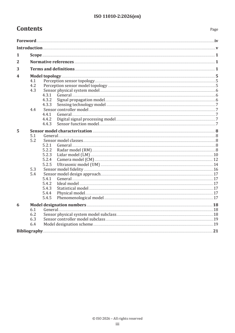
Contents Page
Foreword .iv
Introduction .v
1 Scope . 1
2 Normative references . 1
3 Terms and definitions . 1
4 Model topology . 5
4.1 Perception sensor topology . .5
4.2 Perception sensor model topology .5
4.3 Sensor physical system model .6
4.3.1 General .6
4.3.2 Signal propagation model . .6
4.3.3 Sensing technology model .7
4.4 Sensor controller model .7
4.4.1 General .7
4.4.2 Digital signal processing model .7
4.4.3 Sensor function model . .7
5 Sensor model characterization . 8
5.1 General .8
5.2 Sensor model classes .8
5.2.1 General .8
5.2.2 Radar model (RM) . .8
5.2.3 Lidar model (LM) .10
5.2.4 Camera model (CM) . 12
5.2.5 Ultrasonic model (UM) .14
5.3 Sensor model fidelity .16
5.4 Sensor model design approach.17
5.4.1 General .17
5.4.2 Ideal model .17
5.4.3 Statistical model .17
5.4.4 Physical model .17
5.4.5 Phenomenological model .17
6 Model designation numbers .18
6.1 General .18
6.2 Sensor physical system model subclass .18
6.3 Sensor controller model subclass .19
6.4 Model designation scheme .19
Bibliography .21
iii
Foreword
ISO (the International Organization for Standardization) is a worldwide federation of national standards
bodies (ISO member bodies). The work of preparing International Standards is normally carried out through
ISO technical committees. Each member body interested in a subject for which a technical committee
has been established has the right to be represented on that committee. International organizations,
governmental and non-governmental, in liaison with ISO, also take part in the work. ISO collaborates closely
with the International Electrotechnical Commission (IEC) on all matters of electrotechnical standardization.
The procedures used to develop this document and those intended for its further maintenance are described
in the ISO/IEC Directives, Part 1. In particular, the different approval criteria needed for the different types
of ISO documents should be noted. This document was drafted in accordance with the editorial rules of the
ISO/IEC Directives, Part 2 (see www.iso.org/directives).
ISO draws attention to the possibility that the implementation of this document may involve the use of (a)
patent(s). ISO takes no position concerning the evidence, validity or applicability of any claimed patent
rights in respect thereof. As of the date of publication of this document, ISO had not received notice of (a)
patent(s) which may be required to implement this document. However, implementers are cautioned that
this may not represent the latest information, which may be obtained from the patent database available at
www.iso.org/patents. ISO shall not be held responsible for identifying any or all such patent rights.
Any trade name used in this document is information given for the convenience of users and does not
constitute an endorsement.
For an explanation of the voluntary nature of standards, the meaning of ISO specific terms and expressions
related to conformity assessment, as well as information about ISO's adherence to the World Trade
Organization (WTO) principles in the Technical Barriers to Trade (TBT), see www.iso.org/iso/foreword.html.
This document was prepared by Technical Committee ISO/TC 22, Road vehicles, Subcommittee SC 33, Vehicle
dynamics, chassis components and driving automation systems testing.
A list of all parts in the ISO 11010 series can be found on the ISO website.
Any feedback or questions on this document should be directed to the user’s national standards body. A
complete listing of these bodies can be found at www.iso.org/members.html.
iv
Introduction
This document was developed in response to worldwide demand for standardization of simulation models
and their requirements in specific scenarios as use cases. During development and test of road vehicles,
the question arises of how good simulation models have to be for performing certain use cases. Without
standardization, it is common practice that experts in different organizations develop their own methods
and processes to answer this question. When it comes to comparability and model exchange between project
partners, obstacles occur.
The main purpose of this document is to provide a framework that enables a systematic characterization
of perception sensor simulation models. This document does not consider specific sensor effects for
classification. The simulation models are classified into certain model classes, their designation number and
related elements, characteristics and common modelling methods. The assignment is the responsibility of
the user or can be specified by other regulations and standards.
v
International Standard ISO 11010-2:2026(en)
Passenger cars — Simulation model classification —
Part 2:
Perception sensor models for ADAS/AD
1 Scope
This document specifies a classification framework and terminology of simulation models for perception
sensors in advanced driver assistance systems and automated driving (ADAS/AD) use cases. It builds upon
[1]
the overall framework defined in ISO 11010-1 , which is applicable to vehicle dynamic models.
This document focuses on perception sensor models for radar, camera, lidar and ultrasonic sensors.
This document enables a structured approach for perception sensor model selection and provides a
foundation for consistent sensor model comparison. The model classification is based on the modelling
approach of the sensor model and its environment, as well as the necessary inputs and outputs of the model.
2 Normative references
There are no normative references in this document.
3 Terms and definitions
For the purposes of this document, the following terms and definitions apply.
ISO and IEC maintain terminology databases for use in standardization at the following addresses:
— IEC Electropedia: available at http:// www .electropedia .org/
— ISO Online browsing platform: available at http:// www .iso .org/ obp
3.1
simulation model
mathematical model for the calculation of the system state variables based on equations describing a vehicle
or vehicle sub-system
[2]
[SOURCE: ISO 11010-1:2022 , 3.1, modified — Note 1 to entry has been deleted.]
3.2
model class
category of simulation models (3.1) of a vehicle or a vehicle sub-system
EXAMPLE Radar perception sensor model class.
3.3
model subclass
subclassification of a model class (3.2), including the separation of sensor physical system model and
controller model parts of the overall model class into individual subclasses
EXAMPLE Radar perception sensor physical system model subclass.
3.4
model designation number
gradation of model type and depth with associated model characteristics, represented effects and minimal
model inputs and outputs
[2]
[SOURCE: ISO 11010-1:2022 , 3.3]
3.5
core environment model
core part of the simulation model (3.1) of the physical world outside of the vehicle required to keep track of
the state of the world, excluding any rendering or signal propagation (3.10) modelling
Note 1 to entry: Not the vehicle-internal model of its surroundings.
3.6
perception sensor
hardware and software components embedded in a vehicle to gather information about its surrounding
environment, including any initial processing of this information in terms of feature (3.30), detection (3.31),
or object (3.29) identification, tracking and classification
3.7
perception sensor model
simulation model (3.1) of a perception sensor (3.6)
3.8
sensor physical system
part of the perception sensor (3.6) that comprises the internal signal propagation (3.12) and sensing technology
(3.14) parts of the overall sensor including all analogue processing and the initial conversion into the digital
domain
3.9
sensor physical system model
simulation model (3.1) of the sensor physical system (3.8)
3.10
signal propagation
transmission path of signals between a perception sensor (3.6) and the environment, which is unidirectional
for passive sensors and bidirectional for active sensors
3.11
external signal propagation
part of the signal propagation (3.10) that occurs external to the perception sensor (3.6) component
EXAMPLE The propagation of radio waves of a radar perception sensor once they have left the sensor component
and their return path until entering the sensor component form the external signal propagation.
3.12
internal signal propagation
part of the signal propagation (3.10) that occurs inside the perception sensor (3.6) component
EXAMPLE The optical train of a camera perception sensor forms part of the internal signal propagation.
3.13
signal propagation model
simulation model (3.1) of the signal propagation (3.10) path between environment and perception sensor (3.6)
or a part of the signal propagation (3.10) path
3.14
sensing technology
physical signal conversion used by the perception sensor (3.6) to acquire needed signals including conversion
into the digital domain
3.15
sensing technology model
simulation model (3.1) of the sensing technology (3.14) part of a perception sensor (3.6)
3.16
sensor controller
part of the perception sensor (3.6) that performs the signal processing and sensor functions in the digital
domain
3.17
sensor controller model
simulation model (3.1) of the sensor controller (3.16) part of a perception sensor (3.6)
3.18
digital signal processing
DSP
processing of the sensing technology (3.14) output signals performed in the digital domain with the intent of
providing improved signal-based input to the higher-level sensor function (3.21)
3.19
field-programmable gate array
FPGA
type of configurable integrated circuit that can be repeatedly programmed after manufacturing and is often
used in digital signal processing (3.18) applications requiring configurable massively parallel operation
3.20
digital signal processing model
simulation model (3.1) of the digital signal processing (3.18) part of a perception sensor (3.6)
3.21
sensor function
object (3.29) detection, identification, classification, tracking and localization functions performed on the
converted physical signals
Note 1 to entry: The sensor function is a specific set of functions not necessarily reflective of the broader terms sensor
or perception.
3.22
sensor function model
simulation model (3.1) of the sensor function (3.21) part of a perception sensor (3.6)
3.23
vehicle function
specific component of a vehicle that relies on information gained from one or more perception sensors (3.6)
to perform its intended function
EXAMPLE Automated lane keeping system (ALKS): based on the images of one or more cameras, the position and
orientation of the host vehicle are derived. The ALKS is requesting steering inputs to let the host vehicle follow the
lane.
3.24
vehicle function model
simulation model (3.1) of a vehicle function (3.23)
3.25
vehicle model
overall simulation model (3.1) of a vehicle
3.26
input interface
data required by a simulation model (3.1) to perform its function
3.27
output interface
data provided by a simulation model (3.1) as a result of performing its function
3.28
field of view
FoV
characteristic restricted spatial view of the perception sensor (3.6) into its environment
3.29
object
representation of a real-world entity with defined boundaries and characteristics in the vehicle coordinate
system
Note 1 to entry: The geometric description of the object is in the vehicle coordinate system.
Note 2 to entry: Object signals are basically sensor technology independent. Sensor technology-specific signals may
extend the object signals.
[3]
[SOURCE: ISO 23150-1:2026 , 3.2.7 modified — Examples and references to other terms have been
removed.]
3.30
feature
sensor technology-specific entity represented in the vehicle coordinate system based on multiple
measurements
Note 1 to entry: Multiple measurements can originate from a sensor cluster.
Note 2 to entry: Multiple measurements can originate from multiple measurement cycles.
Note 3 to entry: The term feature is used in this document not as function or group of functions as specified in ISO/
[4]
SAE PAS 22736:2021 .
[3]
[SOURCE: ISO 23150-1:2026 , 3.2.5 modified — References to other terms have been removed.]
3.31
detection
sensor technology-specific entity represented in the sensor coordinate system based on a single
measurement of a sensor
Note 1 to entry: A small amount of history can be used for some detection signals, for example, model-free filtering
may be used in track-before-detect algorithms.
Note 2 to entry: Raw data at this level of information can be referred to using the more specific terms reflection (3.32)
or image (3.33), depending on context, data formats and sensor technology.
[3]
[SOURCE: ISO 23150-1:2026 , 3.2.1 modified — References to other terms have been removed and Note 2
to entry washas been added.]
3.32
reflection
single measurement of intensity, phase, polarization, or any combination thereof, performed by an active
sensor, including radar and lidar sensors, that corresponds to a return signal of an emitted signal represented
in a sensor detector-specific coordinate system
Note 1 to entry: See detection (3.31) for the more generic term for this level of information, as used in ISO 23150-1:2026
[3]
.
3.33
image
two-dimensional rectilinear grid representation of the environment where the information at each point in
the representation, given by brightness, colour, depth, or other information, is related to the output signal
from the sensing technology (3.14) detector directly or through some form of digital signal processing (3.18)
Note 1 to entry: See detection (3.31) for the more generic term for this level of information, as used in ISO 23150-1:2026
[3]
.
4 Model topology
4.1 Perception sensor topology
The following stylized structure of perception sensors forms the basis of the definition of a corresponding
sensor model topology in 4.2.
A perception sensor typically involves a number of distinct parts that together perform the function of the
perception sensor, as shown in Figure 1:
— A signal propagation path from the surrounding environment to the actual sensing technology detection
mechanism of the sensor. Parts of this path reside outside of the sensor itself (e.g. the air), constituting
the external signal propagation, while some parts like an optical train of a camera reside inside the
sensor, constituting the internal signal propagation. For an active sensor like radar or lidar, the signal
propagation path is bidirectional, for a passive sensor like a camera it is unidirectional.
— The actual sensing technology part of the perception sensor that detects the signals and converts them,
potentially via other physical domains, into the digital domain.
— Any digital signal processing steps that are focussed on improving the signal for the higher-level sensor
functions.
— The higher-level sensor function, including object extraction, tracking and any other further processing
that is part of the overall perception sensor function. This includes the handling of all external
communication interfaces, whether at detection, feature, or object level.
The internal signal propagation and sensing technology parts constitute the sensor physical system,
whereas the digital signal processing and sensor function parts constitute the sensor controller.
The data produced by a perception sensor are consumed by one or more vehicle functions, either directly
or indirectly via sensor fusion or other intermediary processing steps, which are subsumed in the vehicle
function for purposes of the overall topology.
Similarly, the signal propagation interacts with the environment in which the vehicle operates.
Figure 1 — Stylized structure of a perception sensor in its real-world context
4.2 Perception sensor model topology
Based on the sensor topology of 4.1, a corresponding nominal perception sensor model topology can be
defined as shown in Figure 2:
Figure 2 — Nominal topology of a perception sensor model in its simulation context
The nominal model topology can be separated into two major simulation model blocks, the sensor physical
system model, comprising the modelled parts of the signal propagation and the sensing technology, and the
sensor controller model, comprising the digital signal processing and sensor function aspects.
The nominal model topology is defined purely for the purpose of model classification. It does not specify
the actual separation into separate model components. The separation into blocks in the topology and the
overall "Perception sensor model" box does not imply that these are the actual boundaries of models used
to model the perception sensor. The perception sensor model could be split up into multiple models for
individual parts thereof without violating the nominal topology. Similarly, many parts can be modelled in a
combined fashion in an overall model.
The overall perception sensor model interacts with one or more vehicle function models that consume the
data provided by the perception sensor models. In closed-loop simulations, these form part of an overall
vehicle model, which feeds back into the core environment model for state updates of the vehicle in its
environment.
For access to the state of the environment, the signal propagation model interacts with the core environment
model.
The interfaces between the individual parts of the model topology are characterized in the technology-
specific subclauses of Clause 5. They form part of the model classification scheme of Clause 6 due to the
input interface and output interface based level of detail classifications. Besides the major data interfaces
as indicated in the topology, additional control interfaces can be present that are needed to feed control
information back into preceding model from later processing stages. Where relevant, these are also specified
in technology-specific subclauses of Clause 5.
4.3 Sensor physical system model
4.3.1 General
The sensor physical system model covers the parts of the perception sensor model that are concerned with
physical signal propagation and conversion into the digital domain.
In the model classification scheme of Clause 6, this forms a model subclass.
4.3.2 Signal propagation model
The signal propagation model covers the signal propagation path from the surrounding environment to the
actual sensing technology detection mechanism of the sensor. For active sensors, this also includes the signal
propagation from the sensor into the environment (bidirectional signal propagation). For passive sensors,
the signal propagation is unidirectional.
Parts of the signal propagation path reside outside of the sensor itself (e.g. the air), termed the external
signal propagation, while some parts like an optical train of a camera reside inside the sensor, termed
internal signal propagation.
The extent to which the signal propagation model is included in the overall perception sensor model,
and to which extent it employs models outside the overall perception sensor is an important aspect of
model classification, as defined in Clause 6. This also affects the way these models interact with the core
environment model.
4.3.3 Sensing technology model
The sensing technology model covers the part of the perception sensor that detects the signals as propagated
and converts them, potentially via conversions to other physical domains, into the digital domain. For active
sensors, this also covers the generation of signals emitted from the sensor.
EXAMPLE 1 For a camera perception sensor, the sensing technology model can include the conversion of light
rays to electrical signals in a charge-coupled device (CCD) imager, their amplification and readout, as well as their
conversion to the digital domain via analogue to digital conversion (ADC).
EXAMPLE 2 For a radar perception sensor, the sensing technology model can include the generation of radar
waves via oscillators, modulators and amplifiers, including their transmission via antenna, as well as their reception
via antenna, amplification, any potential demodulation and conversion to the digital domain via analogue to digital
conversion (ADC).
4.4 Sensor controller model
4.4.1 General
The sensor controller model is concerned with all computational processing aspects of the perception
sensor, including processing hardware like DSP or field-programmable gate array (FPGA) systems, as well
as all software aspects. This model can be separated into the following notional sub-models.
In the model classification scheme of Clause 6, this forms a model subclass.
4.4.2 Digital signal processing model
The digital signal processing model comprises the modelling of any digital signal processing steps that are
focussed on improving the signal coming from the sensing technology model for the higher-level sensor
functions modelled in the sensor function model.
This includes all generic filtering or other transformations performed on the signal to improve signal
detection capabilities, as well as the initial stages of detection or feature extraction. It depends on the sensor
implementation and modelling choices how far the extraction process itself is handled as part of DSP, and to
what extent it is processed as part of the sensor function.
Usually, final classification of detections and features, as well as object extraction and tracking are
considered part of the sensor function and hence modelled as part of the sensor function model.
4.4.3 Sensor function model
This model represents the higher-level sensor function, including object extraction, tracking and any other
further processing that is part of the overall perception sensor function. This most commonly comprises
the final classification of detections and features, as well as object extraction, classification and tracking
functionality.
The sensor function includes the handling of all external communication interfaces, whether at detection,
feature or object level, and is part of the functionality modelled in the sensor function model. While at
least the initial stages of detection or feature extraction are usually handled as part of the digital signal
processing modelled in the DSP model, any further processing, including final classification, the preparation
of this data for communication to the outside world, as well as the actual communication handling are part
of the sensor function model.
5 Sensor model characterization
5.1 General
Sensor models are characterised according to the following aspects:
— sensor model class, i.e. physical sensing technique (see 5.2);
— sensor model fidelity (see 5.3);
— sensor model design approach (see 5.4).
5.2 Sensor model classes
5.2.1 General
This document takes into account four sensor model classes, reflecting the physical mode of operation
(sensing technology) of the sensors being modelled, namely radar, lidar, camera and ultrasonic sensors.
5.2.2 Radar model (RM)
5.2.2.1 Radar sensor topology
The radar sensor topology shown in Figure 3 presents the sensing signal flow of a radar sensor, including the
sensor physical system and the sensor controller. The sensor physical system is divided into the frontend,
containing all necessary components to handle the received signals and those to be transmitted, and the
antennas acting as an interface to the external signal propagation within the environment. As radar sensors
are active sensors, the sensor physical system comprises a transmit path and is bidirectional accordingly.
Figure 3 — Radar perception sensor topology
Once the received signals are handled by the sensor physical system, the digitized baseband d
...