

ISO 13373-9:2026
(Main)Condition monitoring and diagnostics of machines — Vibration condition monitoring — Part 9: Diagnostic techniques for electric motors
General Information
- Abstract
This document specifies the procedures to be considered when carrying out vibration diagnostics of various types of electric motors. The four motor types covered by this document are squirrel-cage induction, wound-rotor induction, salient-pole, and DC. NOTE Motor types a) and b) are defined in ISO 20958. This document is mostly applicable to motors with power above 15 kW. This document is intended to be used by condition monitoring practitioners, engineers and technicians and provides a practical step-by-step vibration-based approach to fault diagnosis. In addition, it gives several examples for a range of machine and component types and their associated fault symptoms. The procedures presented in this document can, in some cases, be applied to other types of electrical machines, such as generators, but there can be other specific techniques associated with such machines that are not included in this document. The use of non-vibration quantities, such as voltage and current, to identify and analyse vibration-related faults in electric motors is outside the scope of this document.
- Status
- Published
- Publication Date
- 10-Aug-2026
- Current Stage
- 6060 - International Standard published
- Start Date
- 11-Aug-2026
- Due Date
- 09-Mar-2026
- Completion Date
- 11-Aug-2026


Overview
ISO 13373-9:2026 - Condition Monitoring and Diagnostics of Machines – Vibration Condition Monitoring – Part 9: Diagnostic Techniques for Electric Motors is an international standard developed by the International Organization for Standardization (ISO). This standard establishes comprehensive procedures for conducting vibration diagnostics on various types of electric motors, specifically focusing on squirrel-cage induction, wound-rotor induction, salient-pole, and DC motors. The document is particularly applicable to electric motors with power ratings above 15 kW and is intended to guide condition monitoring practitioners, engineers, and technicians through a step-by-step vibration-based approach to fault diagnosis.
This part of ISO 13373 enables organizations to systematically identify and diagnose faults in electric motors using vibration analysis, supporting predictive maintenance strategies, reducing downtime, and improving machine reliability in industrial environments.
Key Topics
ISO 13373-9:2026 covers several critical areas related to vibration condition monitoring and diagnostics for electric motors:
- Procedures for Vibration Measurements: Guidelines on selecting and utilizing appropriate transducers (such as accelerometers and eddy current probes) and assessment of motor vibration severity in line with ISO 10816 and ISO 20816 series.
- Analysis Techniques: Outlines visual inspections, spectral analysis, time waveform analysis, phase analysis, and operational deflection shape (ODS) analysis for effective vibration diagnosis.
- Motor-Specific Fault Diagnosis: Diagnostic steps and practical tables with common electric motor faults (e.g., loose stator coils, bent shafts, cracked rotor bars), their symptoms, and typical corrective actions.
- Systematic Evaluation Approach: Use of diagnostic flowcharts, process tables, and fault/symptom tables for a systematic and structured diagnosis workflow, ensuring thorough anomaly assessment and root cause identification.
- Influencing Parameters: Emphasis on monitoring key operational parameters such as rotational speed, load, orientation, mounting configuration, and temperature, as these can impact vibration characteristics.
The standard explicitly excludes the use of non-vibration quantities (such as voltage and current) in diagnosing vibration-related faults.
Applications
Implementation of ISO 13373-9:2026 provides significant practical value in a range of industrial and commercial environments:
- Predictive Maintenance: Enables facilities to adopt advanced condition monitoring programs, proactively identifying motor faults to prevent unexpected failures and extend machine life.
- Industrial Asset Management: Supports reliability engineers and maintenance teams in oil & gas, manufacturing, utilities, and process industries to optimize equipment uptime.
- Commissioning & Troubleshooting: Serves as a reference during motor installation, commissioning, and when investigating vibration anomalies or performance issues.
- Training and Standardization: Used as a guide for educating field technicians and engineers in best practices for vibration analysis and motor diagnostics, ensuring consistency in maintenance operations.
- Quality Assurance: Helps maintain high operational standards by providing structured assessment frameworks for fault detection and decision-making.
This standard is also adaptable for analytical work on similar types of electrical machines, such as generators, although it does not cover specific generator diagnostic techniques.
Related Standards
Professionals utilizing ISO 13373-9:2026 for electric motor vibration diagnostics should also be aware of these related international standards:
- ISO 13373-1: General procedures for vibration condition monitoring of machines.
- ISO 13373-2: Processing, analysis, and presentation of vibration data.
- ISO 13373-3: Diagnosis of faults common to rotating machines.
- ISO 10816 / ISO 20816 Series: Criteria for assessment of vibration severity.
- ISO 20958: Electrical signature analysis of three-phase induction motors.
- ISO 2041 / ISO 13372: Vibration and condition monitoring vocabulary.
- ISO 21940-2: Vocabulary for rotor balancing.
Referencing these standards alongside ISO 13373-9:2026 enhances the effectiveness of vibration condition monitoring and supports comprehensive asset management in electric motor applications.
By following ISO 13373-9:2026, organizations can confidently establish a reliable, standardized approach to electric motor diagnostics and proactive maintenance using vibration monitoring techniques.
Relations
- Effective Date
- 11-Mar-2023
Get Certified
Connect with accredited certification bodies for this standard

BSMI (Bureau of Standards, Metrology and Inspection)
Taiwan's standards and inspection authority.
Sponsored listings
Frequently Asked Questions
ISO 13373-9:2026 is a standard published by the International Organization for Standardization (ISO). Its full title is "Condition monitoring and diagnostics of machines — Vibration condition monitoring — Part 9: Diagnostic techniques for electric motors". This standard covers: This document specifies the procedures to be considered when carrying out vibration diagnostics of various types of electric motors. The four motor types covered by this document are squirrel-cage induction, wound-rotor induction, salient-pole, and DC. NOTE Motor types a) and b) are defined in ISO 20958. This document is mostly applicable to motors with power above 15 kW. This document is intended to be used by condition monitoring practitioners, engineers and technicians and provides a practical step-by-step vibration-based approach to fault diagnosis. In addition, it gives several examples for a range of machine and component types and their associated fault symptoms. The procedures presented in this document can, in some cases, be applied to other types of electrical machines, such as generators, but there can be other specific techniques associated with such machines that are not included in this document. The use of non-vibration quantities, such as voltage and current, to identify and analyse vibration-related faults in electric motors is outside the scope of this document.
This document specifies the procedures to be considered when carrying out vibration diagnostics of various types of electric motors. The four motor types covered by this document are squirrel-cage induction, wound-rotor induction, salient-pole, and DC. NOTE Motor types a) and b) are defined in ISO 20958. This document is mostly applicable to motors with power above 15 kW. This document is intended to be used by condition monitoring practitioners, engineers and technicians and provides a practical step-by-step vibration-based approach to fault diagnosis. In addition, it gives several examples for a range of machine and component types and their associated fault symptoms. The procedures presented in this document can, in some cases, be applied to other types of electrical machines, such as generators, but there can be other specific techniques associated with such machines that are not included in this document. The use of non-vibration quantities, such as voltage and current, to identify and analyse vibration-related faults in electric motors is outside the scope of this document.
ISO 13373-9:2026 is classified under the following ICS (International Classification for Standards) categories: 17.160 - Vibrations, shock and vibration measurements. The ICS classification helps identify the subject area and facilitates finding related standards.
ISO 13373-9:2026 has the following relationships with other standards: It is inter standard links to ISO 13373-9:2017. Understanding these relationships helps ensure you are using the most current and applicable version of the standard.
ISO 13373-9:2026 is available in PDF format for immediate download after purchase. The document can be added to your cart and obtained through the secure checkout process. Digital delivery ensures instant access to the complete standard document.
Standards Content (Sample)
International
Standard
ISO 13373-9
Second edition
Condition monitoring and
2026-08
diagnostics of machines —
Vibration condition monitoring —
Part 9:
Diagnostic techniques for electric
motors
Surveillance et diagnostic d'état des machines — Surveillance des
vibrations —
Partie 9: Techniques de diagnostic pour moteurs électriques
Reference number
© ISO 2026
All rights reserved. Unless otherwise specified, or required in the context of its implementation, no part of this publication may
be reproduced or utilized otherwise in any form or by any means, electronic or mechanical, including photocopying, or posting on
the internet or an intranet, without prior written permission. Permission can be requested from either ISO at the address below
or ISO’s member body in the country of the requester.
ISO copyright office
CP 401 • Ch. de Blandonnet 8
CH-1214 Vernier, Geneva
Phone: +41 22 749 01 11
Email: copyright@iso.org
Website: www.iso.org
Published in Switzerland
ii
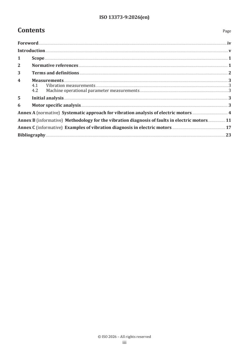
Contents Page
Foreword .iv
Introduction .v
1 Scope . 1
2 Normative references . 1
3 Terms and definitions . 2
4 Measurements . 3
4.1 Vibration measurements .3
4.2 Machine operational parameter measurements .3
5 Initial analysis . 3
6 Motor specific analysis . 3
Annex A (normative) Systematic approach for vibration analysis of electric motors . 4
Annex B (informative) Methodology for the vibration diagnosis of faults in electric motors .11
Annex C (informative) Examples of vibration diagnosis in electric motors . 17
Bibliography .23
iii
Foreword
ISO (the International Organization for Standardization) is a worldwide federation of national standards
bodies (ISO member bodies). The work of preparing International Standards is normally carried out through
ISO technical committees. Each member body interested in a subject for which a technical committee
has been established has the right to be represented on that committee. International organizations,
governmental and non-governmental, in liaison with ISO, also take part in the work. ISO collaborates closely
with the International Electrotechnical Commission (IEC) on all matters of electrotechnical standardization.
The procedures used to develop this document and those intended for its further maintenance are described
in the ISO/IEC Directives, Part 1. In particular, the different approval criteria needed for the different types
of ISO document should be noted. This document was drafted in accordance with the editorial rules of the
ISO/IEC Directives, Part 2 (see www.iso.org/directives).
ISO draws attention to the possibility that the implementation of this document may involve the use of (a)
patent(s). ISO takes no position concerning the evidence, validity or applicability of any claimed patent
rights in respect thereof. As of the date of publication of this document, ISO had not received notice of (a)
patent(s) which may be required to implement this document. However, implementers are cautioned that
this may not represent the latest information, which may be obtained from the patent database available at
www.iso.org/patents. ISO shall not be held responsible for identifying any or all such patent rights.
Any trade name used in this document is information given for the convenience of users and does not
constitute an endorsement.
For an explanation of the voluntary nature of standards, the meaning of ISO specific terms and expressions
related to conformity assessment, as well as information about ISO's adherence to the World Trade
Organization (WTO) principles in the Technical Barriers to Trade (TBT), see www.iso.org/iso/foreword.html.
This document was prepared by Technical Committee ISO/TC 108, Mechanical vibration, shock and condition
monitoring, Subcommittee SC 2, Measurement and evaluation of mechanical vibration and shock as applied to
machines, vehicles and structures.
This second edition cancels and replaces the first edition (ISO 13373-9:2017), which has been technically
revised.
The main changes are as follows:
— unused terms have been deleted;
— Table A.2 has been added;
— Clause A.2 with descriptions of tests related to Table A.1 and Table A.2 has been added;
— references have been updated;
— document has been editorially revised.
A list of all parts in the ISO 13373 series can be found on the ISO website.
Any feedback or questions on this document should be directed to the user’s national standards body. A
complete listing of these bodies can be found at www.iso.org/members.html.
iv
Introduction
This document has been developed as a guideline for the procedures to be considered when carrying out
vibration diagnostics of electric motors. It is intended to be used by vibration practitioners, engineers
and technicians and provides them with useful diagnostic tools. These tools include the use of diagnostic
flowcharts, process tables and fault tables. The material contained in this document presents the most basic,
logical and intelligent steps that should be taken when diagnosing problems associated with these types of
machines.
The ISO 10816 series and ISO 20816 series contain acceptable vibration levels and zones for various types
and sizes of machines, ranging from new and well-running to those that are in danger of failing.
ISO 13373-1 presents the basic procedures for carrying out vibration narrow-band signal analysis. It includes
the types of transducers used, their ranges and their recommended locations on various types of machines,
online and periodic vibration monitoring systems and the detection of potential machine problems.
ISO 13373-2 includes descriptions of the signal conditioning equipment that is required, time and frequency
domain techniques and the waveforms and signatures that represent the most common machines operating
phenomena or machine faults that are encountered when performing vibration signature analysis.
ISO 13373-3 sets out some procedures to determine the causes of vibration problems common to all types of
rotating machines. It includes systematic approaches to characterizing vibration effects, the diagnostic tools
available, which tools are needed for particular applications, and recommendations on how the tools are to
be applied to different types of machines and components. However, this does not preclude the use of other
diagnostic techniques.
ISO 17359 indicates that diagnostics
a) can be started as a succeeding activity after the detection of an anomaly during machine monitoring, or
b) can be executed synchronous with monitoring from the beginning.
This document considers only a) in which diagnostics is performed after an anomaly has been detected.
Moreover, this document focuses mainly on the use of flowcharts, process tables, fault and symptom tables
as diagnostic tools, since it is felt that these are the tools that are most appropriate for use by practitioners,
engineers and technicians in the field.
The flowchart and diagnostic process table methodology presents a structured procedure for a person in
the field to diagnose a fault and find its cause. This step-by-step procedure guides the practitioner through
the vibration diagnostics of the machine anomaly in order to reach its probable root cause.
The fault and symptom tables present a list of the most common faults in machines, as well as their
manifestation in the vibration data. When used with the flowcharts, the tables assist with the identification
of machine faults.
When approaching a machine problem that manifests itself as a high or erratic vibration signal, the
diagnosis of the problem should be done in a well-thought-out systematic manner. This document, together
with ISO 13373-3, achieve that by providing the analyst guidance on the selection of the proper measuring
tools, the analysis tools and their use and the step-by-step recommended procedures to diagnose problems
associated with various types of electric motors.
v
International Standard ISO 13373-9:2026(en)
Condition monitoring and diagnostics of machines —
Vibration condition monitoring —
Part 9:
Diagnostic techniques for electric motors
1 Scope
This document specifies the procedures to be considered when carrying out vibration diagnostics of various
types of electric motors. The four motor types covered by this document are
a) squirrel-cage induction,
b) wound-rotor induction,
c) salient-pole, and
d) DC.
NOTE Motor types a) and b) are defined in ISO 20958.
This document is mostly applicable to motors with power above 15 kW.
This document is intended to be used by condition monitoring practitioners, engineers and technicians and
provides a practical step-by-step vibration-based approach to fault diagnosis. In addition, it gives several
examples for a range of machine and component types and their associated fault symptoms.
The procedures presented in this document can, in some cases, be applied to other types of electrical
machines, such as generators, but there can be other specific techniques associated with such machines that
are not included in this document.
The use of non-vibration quantities, such as voltage and current, to identify and analyse vibration-related
faults in electric motors is outside the scope of this document.
2 Normative references
The following documents are referred to in the text in such a way that some or all of their content constitutes
requirements of this document. For dated references, only the edition cited applies. For undated references,
the latest edition of the referenced document (including any amendments) applies.
ISO 2041, Mechanical vibration, shock and condition monitoring — Vocabulary
ISO 13372, Condition monitoring and diagnostics of machines — Vocabulary
ISO 13373-1, Condition monitoring and diagnostics of machines — Vibration condition monitoring — Part 1:
General procedures
ISO 13373-2, Condition monitoring and diagnostics of machines — Vibration condition monitoring — Part 2:
Processing, analysis and presentation of vibration data
ISO 20958, Condition monitoring and diagnostics of machine systems — Electrical signature analysis of three-
phase induction motors
ISO 21940-2, Mechanical vibration — Rotor balancing — Part 2: Vocabulary
IEC 60050, International Electrotechnical Vocabulary
3 Terms and definitions
For the purposes of this document, the terms and definitions given in ISO 2041, ISO 13372, ISO 20958,
ISO 21940-2, IEC 60050 and the following apply.
ISO and IEC maintain terminology databases for use in standardization at the following addresses:
— IEC Electropedia: available at https:// www .electropedia .org/
— ISO Online browsing platform: available at https:// www .iso .org/ obp
3.1
DC motor
motor including shaft with laminated, slotted core into which a two-layer winding is installed and connected
to a commutator which is supplied with DC power via brushes
3.2
salient-pole rotor
shaft with solid or laminated poles having a winding on each pole
Note 1 to entry: The pole windings are connected together and to sliprings or a brushless exciter from which the
required DC power supply is applied.
3.3
supply frequency
line frequency
frequency of the power supply connected to AC motors
3.4
slip frequency
difference between the synchronous rotational speed and rotor rotational speed
frequencies
3.5
number of stator poles
integer which is defined by the following formula:
120 f /n
supp syn
where
n is the synchronous rotational speed, in r/min;
syn
f is the supply frequency, in Hz.
supp
Note 1 to entry: The number of pole pairs is the number of poles divided by 2.
3.6
stator slot pass frequency
number of stator slots times the rotor rotational speed
3.7
rotor slot pass frequency
number of rotor slots times the rotor rotational speed
3.8
rotor bar pass frequency
number of bars in a squirrel-cage rotor times the rotor rotational speed
4 Measurements
4.1 Vibration measurements
Vibration measurements may be obtained using two main categories of transducers:
— non-contacting (e.g. inductive, capacitive and eddy current probes used on rotating shafts);
— seismic transducers (e.g. accelerometers or velocity transducers used on non-rotating parts, such as
bearing housings).
The ISO 10816 series and ISO 20816 series set out requirements that can help assess the vibration severity
present in a motor.
It is important to recognize that the appropriate transducer, signal conditioning, measurement and analysis
system shall be used for the diagnosis of faults considering specific situations in electric motors. For example,
to detect rotor bar problems, high resolution in the spectrum is required to detect the slip frequency. In
many cases, it is required to consider the grounding and electrical field of the machine before taking any
measurement.
The description of transducer and measurement systems, as well as techniques for their use in fault
diagnosis, are given in ISO 13373-1 and ISO 13373-2, which shall be considered to assist in obtaining the
appropriate selection.
4.2 Machine operational parameter measurements
These are operational parameters, e.g. rotational speed, load, motor orientation (vertical or horizontal),
mounting configuration (solid or flexible support arrangement) and temperatures, that can have an influence
on the machine vibration characteristics and are therefore important to acquire in order to arrive at an
appropriate diagnosis. For a given machine, these parameters can be associated with a range of steady-state
and transient operating conditions.
5 Initial analysis
An initial analysis shall be performed using the guidelines given in ISO 13373-3:2015, Annex A. This analysis
shall identify safety concerns, the presence of high vibration, and if so, its vibration severity, past history,
effects of operating parameters, consequences of not taking corrective actions and the need for motor
shutdown. Also, other factors, e.g. motor mounting configuration, vibration from driven machines, position
relative to other rotating machines, building structure and environment, should be considered during the
initial analysis. See ISO 13373-3:2015, Annexes B to D, for common faults that can arise from installation
and bearing defects.
6 Motor specific analysis
Electric motors are used as drivers in many industrial applications such as pumps, fans and compressors.
This document covers vibration diagnosis for the most common types of electric motors. Symptoms of
the most prevalent motor defects that cause excessive vibration magnitudes are given in Annex A, which
shall be considered. However, Annex A does not cover motor vibration from inadequate motor mounting,
hydrodynamic or rolling bearing problems which are addressed in ISO 13373-3:2015, Annexes B, C and D,
respectively.
The methodology for vibration diagnosis of electric motors is given in Annex B, while case studies illustrating
the methodology are provided in Annex C. The techniques used in vibration diagnosis of electric motors
include visual inspections, vibration magnitudes, spectral analysis, time waveform analysis, phase analysis
and operational deflection shape (ODS) analysis. The use of these techniques is described in B.2.
Annex A
(normative)
Systematic approach for vibration analysis of electric motors
A.1 Fault and symptom tables for vibration analysis
A systematic approach to vibration analysis of electric motors is given by the fault Table A.1 and the symptom
Table A.2.
NOTE To understand as to why specific defects can be identified by certain vibration frequencies and other
characteristics see References [8] and [9].
Table A.1 — Fault table for vibration analysis of electric motors
Fault Conditions under Initial rate Major frequency component Subsequent be- Effect on reso- Effect of cutting Repeatability Comments
which vibration of change of changed vibration ampli- haviour of vibra- nance speed power
change occurs of vibration tude and phase angles tion with time
amplitude
Loose stator Usually gradually Slow rate of Number of stator coils times Magnitudes in- None Immediate drop in Yes Unlikely to occur if stator
coils (synchro- develops with time change rotational speed with 1× rota- crease with time vibration magni- winding is vacuum pressure
nous motors) tional speed sidebands tudes impregnated
Bent shaft Usually occurs Fast rate of Mainly 1× rotational speed, If caused by high None 2× supply frequency Magnitudes Can be confirmed by total
extension after failure of change but exhibit 2× supply frequen- radial load on shaft is supposed to can change indicated runout measurement
driven equipment, cy and modulation of this at 2× extensions, can disappear without with load and on shaft extension
or if a high radial slip frequency in 2-pole squir- increase with time power supply. 1× temperature
load is imposed rel-cage motors if bent shaft and vary with load turning speed de-
leads to non-uniform air gap creases with speed
and/or remains
elevated at low
speeds.
Rotor running After motor in- Depends on High axial 1×, 2× or 3× rota- Can change with None Immediate drop in Magnitudes Higher magnitudes in motors
off magnetic stallation or axial how far rotor tional speed frequency with load vibration magni- can change with radial cooling ducts on
centre realignment with is off its axial much lower radial vibration. tudes with load and stator and rotor
driven equipment magnetic Possibly exciting natural temperature
centre frequencies.
Cracked or bro- After motor start- Slow if fabri- High 1× rotational speed Vibration will Will change Immediate drop in Magnitudes Motor will become noisy during
ken rotor bars ing, unless due to cated rotor frequency with sidebands increase if more response vibration magni- will change if starting and start time will
voids in diecast bars at ± slip frequency times num- rotor bars break. tudes more rotor bars increase due to reduction in
rotor bars ber of poles. Also, harmonics Also unbalance break motor torque. Can usually be
of these frequencies. Vibration and vibration due confirmed by current signature
amplitude can vary at slip fre- to thermal bow analysis and 2× slip frequen-
quency times number of poles will develop. cy sidebands around supply
and increase with load. Can frequency.
also be a high 4× rotational
speed axial vibration.
Loose rotor Unless bars were For developing 2× supply frequency side- Vibration magni- Varies with load Rotor slot pass fre- Yes Excessive looseness and rotor
bars loose from manu- looseness with bands on 1×, 2× or 3× rotor tudes will increase quencies will imme- thermal bow can cause me-
facture, problems service, rate of slot pass frequency compo- with time and can diately disappear. chanical unbalance in higher
will usually start change will be nents vary with load if Unbalance effect speed motors
to develop some slow more bars become frequency compo-
time after motor is loose nent can suddenly
placed in service disappear at some
lower speeds.
Non-uniform Steady load condi- Can develop 2× supply frequency, can have Will likely not None Immediate drop in Yes Can be due to soft foot or flex-
air gap tions slowly with beating with 2× rotational change with time vibration magnitude ible stator, sometimes induced
time speed in 2-pole motors or load by misalignment
Unbalanced Steady load condi- Depends on 2× power supply frequency Vibration magni- None Drops rapidly unless Can be non-re- Voltage unbalance can be from
power supply tions the amount of radial, with 1/3× supply tudes will increase there is a resonance peatable, if supply unbalance, or loose con-
voltages voltage unbal- frequency sidebands, with with the amount of speed below rota- due to a loose nection at motor terminals
ance perhaps an amplitude beat voltage unbalance tional speed connection
Table A.1 (continued)
Fault Conditions under Initial rate Major frequency component Subsequent be- Effect on reso- Effect of cutting Repeatability Comments
which vibration of change of changed vibration ampli- haviour of vibra- nance speed power
change occurs of vibration tude and phase angles tion with time
amplitude
Rotor shaft Steady load condi- Slow initially 1× plus 2×, 3× mainly radial, 1× component Frequency can Can initially drop Can be non-re- Steady-state vibration changes
crack tions some axial dependent upon increases exponen- reduce and split due to loss of peatable can be insignificant. Larger
type of crack. Phase is erratic. tially with time, into two peaks magnetic attraction amplitudes can be evident on
while 2× magni- between rotor and rundown through resonance
tude and phase are stator, then slowly speeds leading to acceleration
unsteady declines afterwards of damage. Observe trends of
harmonic vibration compo-
nents. Compare historic slow-
roll runout and changes in 1×
and some 2× characteristics.
Proximity of Normal operating Immediately 1× rotational speed mainly Likely not to None Drops rapidly unless Yes Shaft displacement measure-
rotor resonance conditions, but can evident radial. Approximately 180° change with time there is a resonance ments are best for detecting
speed to oper- pass through reso- phase shift when crossing a speed below rota- this problem
ating speed nance speed during resonance frequency. tional speed
start up
Proximity of Normal operating Immediately 1× rotational speed radial or Likely not to None Drops rapidly unless Yes
structural conditions, but can evident axial but will dominate in one change with time there is a resonance
resonances pass through reso- plane. Approximately 180° speed below rota-
to operating nance speed during phase shift when crossing a tional speed
speed start up resonant frequency
Salient-pole Steady load condi- Immediately Rotational speed times Will increase if Can change reso- Immediate drop in Yes Sometimes difficult to confirm
rotor shorted tions evident number of poles. Magnitude more shorted nance speed due vibration magnitude since turn shorts can disappear
turns proportional to the number of turns develop to increase in ra- when centrifugal forces present
shorted turns and field cur- dial bearing load during running are not present
rent. Mainly radial vibration from unbalanced with the rotor at standstill
mode. magnetic pull
between rotor
and stator
Loose sali- Steady load and Can develop Rotational speed times Will increase Can change reso- Drops slowly with Yes
ent-poles during starting and slowly with number of stator poles with 1× with further pole nance speed speed
stopping time speed sidebands mainly radial looseness
Stator shorts Steady load condi- Can develop 2× supply frequency and Will increase Not applicable Immediate drop in Yes
tions slowly with multiples if shorted area vibration magnitude
time increases
DC motor bro- Steady load condi- Can develop Usually 6× solid state AC to DC Can increase with Not applicable Immediate drop in Yes
ken field wind- tions slowly with power rectifier firing frequen- increased connec- vibration magnitude
ings and loose time cy (mainly radial) tion looseness
connections
Misalignment See ISO 13373-3:20
...