

ISO 14303:2026
(Main)Space systems — Launch-vehicle-to-spacecraft interfaces
General Information
- Abstract
This document specifies the interfaces between a launch vehicle (LV) and the spacecraft (SC) being launched, to provide LV and SC organizations with the necessary format for presenting the required technical data on existing and future interfaces. Its intended purpose is to minimize costs and reduce the risks from errors resulting from miscommunication. It does not limit the ability of LV or SC organizations to specify unique requirements.
- Status
- Published
- Publication Date
- 09-Aug-2026
- Technical Committee
- ISO/TC 20/SC 14 - Space systems and operations
- Current Stage
- 6060 - International Standard published
- Start Date
- 10-Aug-2026
- Due Date
- 11-Jun-2026
- Completion Date
- 10-Aug-2026
Overview
ISO 14303:2026 is an international standard developed by the International Organization for Standardization (ISO) that specifies requirements for the interfaces between launch vehicles (LV) and spacecraft (SC). This standard offers a unified format for presenting technical data related to current and future LV-SC interfaces, aiming to support LV and SC organizations worldwide. By providing clear and standardized communication protocols for mechanical, electrical, and environmental interfaces, ISO 14303:2026 minimizes costs, reduces risks of miscommunication, and enhances the safety and reliability of space missions. Notably, this document does not restrict organizations from specifying unique or additional requirements suited to their particular missions.
Keywords: LV-SC interfaces, space mission integration, launch vehicle, spacecraft, interface control, ISO space standards
Key Topics
ISO 14303:2026 addresses the following core areas in the context of launch vehicle to spacecraft integration:
- Mechanical Interfaces: Specification of mating configurations, payload adapters, usable volume, and key spacecraft characteristics required for interface compatibility.
- Electrical Interfaces: Guidance on umbilical connectors, telemetry links, pyrotechnic and dry loop commands, power supply continuity, and transmission of separation status signals.
- Radio Frequency/Electromagnetic Compatibility: Protocols for RF telemetry, command links, and managing the electromagnetic environments generated by both the LV and the SC.
- Mission Performance: Frameworks for defining geosynchronous transfer orbits (GTO), elliptical, sun-synchronous, low Earth, circular, and escape mission profiles; includes details on injection accuracy, launch windows, and orientation/separation requirements.
- Environmental and Load Constraints: Expected launch-induced environments such as mechanical loads, acoustic noise, vibration, and thermal conditions, as well as requirements for cleanliness and contamination control.
- Verification and Documentation: Methods for interface verification through analyses and physical tests, and provisions for comprehensive documentation – including interface control documents (ICD), verification plans, and assessment protocols.
- Spacecraft Launch Preparation: Outlines pre-launch operations, hazardous item handling, assembly and checkout procedures, and final integration steps.
Applications
ISO 14303:2026 delivers practical value for a wide spectrum of space industry stakeholders:
- Space Agencies and Satellite Manufacturers: Enables interoperability by providing a universal reference for launch vehicle interface requirements, aiding in satellite design and LV compatibility assessments.
- Launch Services Providers: Facilitates efficient onboarding of multiple types of payloads, supports risk reduction, and improves mission planning and execution consistency.
- Interface Engineers and Mission Planners: Employs standard formats for documenting and exchanging crucial technical data, thus streamlining interface verification, reducing development time, and supporting joint operations from spacecraft preparation to LV integration.
- System Integrators: Standardizes pre-launch verification tasks, including mechanical, electrical, RF, and performance checks, ensuring smooth mission preparation and execution.
- Quality and Safety Teams: Offers systematic procedures for interface verification, risk assessment, and post-launch review to maintain mission integrity and safety.
Related Standards
For complete coverage and best practices in launch vehicle and spacecraft integration, consider the following related ISO standards:
- ISO 15863: Space systems - Interface control documents
- ISO 17401: Space systems - Spacecraft interfaces for launch vehicle services
These standards, together with ISO 14303:2026, provide a comprehensive framework for documenting and verifying interface requirements in space missions.
By establishing a common technical language and process, ISO 14303:2026 fosters greater reliability, safety, and cost-effectiveness in the integration of spacecraft and launch vehicles, supporting the success of increasingly complex international space endeavors.
Relations
- Effective Date
- 15-Jun-2024
Get Certified
Connect with accredited certification bodies for this standard

BUREAU VERITAS Certification Germany
Bureau Veritas certification in Germany.

Element Materials Technology
Materials testing and product certification.

AQMS Ltd.
AQMS provides ISO certification to SMEs across the UK.
Sponsored listings
Frequently Asked Questions
ISO 14303:2026 is a standard published by the International Organization for Standardization (ISO). Its full title is "Space systems — Launch-vehicle-to-spacecraft interfaces". This standard covers: This document specifies the interfaces between a launch vehicle (LV) and the spacecraft (SC) being launched, to provide LV and SC organizations with the necessary format for presenting the required technical data on existing and future interfaces. Its intended purpose is to minimize costs and reduce the risks from errors resulting from miscommunication. It does not limit the ability of LV or SC organizations to specify unique requirements.
This document specifies the interfaces between a launch vehicle (LV) and the spacecraft (SC) being launched, to provide LV and SC organizations with the necessary format for presenting the required technical data on existing and future interfaces. Its intended purpose is to minimize costs and reduce the risks from errors resulting from miscommunication. It does not limit the ability of LV or SC organizations to specify unique requirements.
ISO 14303:2026 is classified under the following ICS (International Classification for Standards) categories: 49.140 - Space systems and operations. The ICS classification helps identify the subject area and facilitates finding related standards.
ISO 14303:2026 has the following relationships with other standards: It is inter standard links to ISO 14303:2002. Understanding these relationships helps ensure you are using the most current and applicable version of the standard.
ISO 14303:2026 is available in PDF format for immediate download after purchase. The document can be added to your cart and obtained through the secure checkout process. Digital delivery ensures instant access to the complete standard document.
Standards Content (Sample)
International
Standard
ISO 14303
Second edition
Space systems — Launch-vehicle-to-
2026-08
spacecraft interfaces
Systèmes spatiaux — Interfaces entre le lanceur spatial et le
véhicule spatial
Reference number
© ISO 2026
All rights reserved. Unless otherwise specified, or required in the context of its implementation, no part of this publication may
be reproduced or utilized otherwise in any form or by any means, electronic or mechanical, including photocopying, or posting on
the internet or an intranet, without prior written permission. Permission can be requested from either ISO at the address below
or ISO’s member body in the country of the requester.
ISO copyright office
CP 401 • Ch. de Blandonnet 8
CH-1214 Vernier, Geneva
Phone: +41 22 749 01 11
Email: copyright@iso.org
Website: www.iso.org
Published in Switzerland
ii
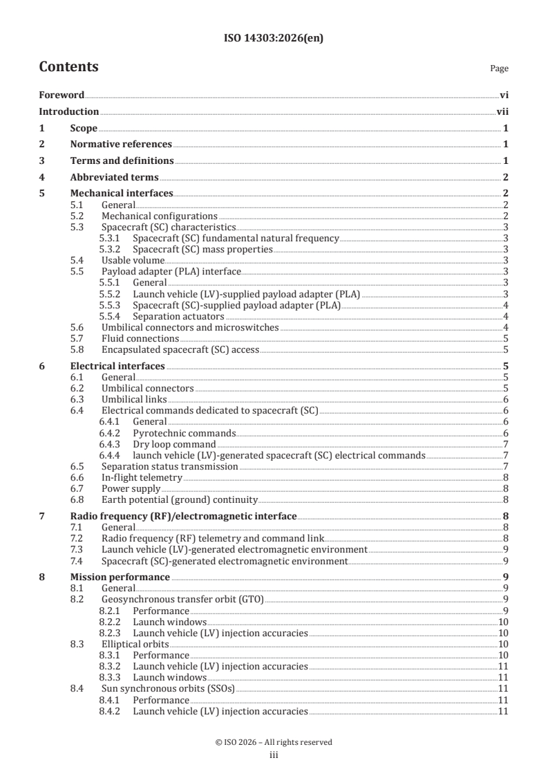
Contents Page
Foreword .vi
Introduction .vii
1 Scope . 1
2 Normative references . 1
3 Terms and definitions . 1
4 Abbreviated terms . 2
5 Mechanical interfaces. 2
5.1 General .2
5.2 Mechanical configurations .2
5.3 Spacecraft (SC) characteristics.3
5.3.1 Spacecraft (SC) fundamental natural frequency .3
5.3.2 Spacecraft (SC) mass properties .3
5.4 Usable volume.3
5.5 Payload adapter (PLA) interface . .3
5.5.1 General .3
5.5.2 Launch vehicle (LV)-supplied payload adapter (PLA) .3
5.5.3 Spacecraft (SC)-supplied payload adapter (PLA) .4
5.5.4 Separation actuators .4
5.6 Umbilical connectors and microswitches .4
5.7 Fluid connections .5
5.8 Encapsulated spacecraft (SC) access .5
6 Electrical interfaces . 5
6.1 General .5
6.2 Umbilical connectors .5
6.3 Umbilical links .6
6.4 Electrical commands dedicated to spacecraft (SC) .6
6.4.1 General .6
6.4.2 Pyrotechnic commands .6
6.4.3 Dry loop command .7
6.4.4 launch vehicle (LV)-generated spacecraft (SC) electrical commands .7
6.5 Separation status transmission .7
6.6 In-flight telemetry .8
6.7 Power supply .8
6.8 Earth potential (ground) continuity .8
7 Radio frequency (RF)/electromagnetic interface . 8
7.1 General .8
7.2 Radio frequency (RF) telemetry and command link .8
7.3 Launch vehicle (LV)-generated electromagnetic environment .9
7.4 Spacecraft (SC)-generated electromagnetic environment .9
8 Mission performance . 9
8.1 General .9
8.2 Geosynchronous transfer orbit (GTO) .9
8.2.1 Performance .9
8.2.2 Launch windows .10
8.2.3 Launch vehicle (LV) injection accuracies .10
8.3 Elliptical orbits .10
8.3.1 Performance .10
8.3.2 Launch vehicle (LV) injection accuracies .11
8.3.3 Launch windows .11
8.4 Sun synchronous orbits (SSOs) .11
8.4.1 Performance .11
8.4.2 Launch vehicle (LV) injection accuracies .11
iii
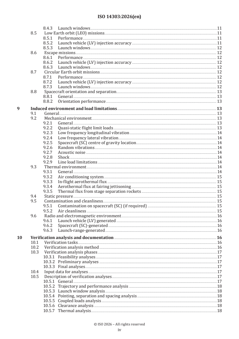
8.4.3 Launch windows .11
8.5 Low Earth orbit (LEO) missions.11
8.5.1 Performance .11
8.5.2 Launch vehicle (LV) injection accuracy .11
8.5.3 Launch windows . 12
8.6 Escape missions . 12
8.6.1 Performance . 12
8.6.2 Launch vehicle (LV) injection accuracy . 12
8.6.3 Launch windows . 12
8.7 Circular Earth orbit missions . 12
8.7.1 Performance . 12
8.7.2 Launch vehicle (LV) injection accuracy . 12
8.7.3 Launch windows . 12
8.8 Spacecraft orientation and separation. 13
8.8.1 General . 13
8.8.2 Orientation performance . 13
9 Induced environment and load limitations .13
9.1 General . 13
9.2 Mechanical environment . 13
9.2.1 General . 13
9.2.2 Quasi-static flight limit loads . 13
9.2.3 Low frequency longitudinal vibration .14
9.2.4 Low frequency lateral vibration .14
9.2.5 Spacecraft (SC) centre of gravity location .14
9.2.6 Random vibrations .14
9.2.7 Acoustic noise .14
9.2.8 Shock .14
9.2.9 Line load limitations .14
9.3 Thermal environment .14
9.3.1 General .14
9.3.2 Air conditioning system . 15
9.3.3 In-flight aerothermal flux . 15
9.3.4 Aerothermal flux at fairing jettisoning . 15
9.3.5 Thermal flux from stage separation rockets . 15
9.4 Static pressure . 15
9.5 Contamination and cleanliness . . 15
9.5.1 Contamination on spacecraft (SC) (if required) . 15
9.5.2 Air cleanliness . 15
9.6 Radio and electromagnetic environment .16
9.6.1 Launch vehicle (LV) generated .16
9.6.2 Spacecraft (SC)-generated .16
9.6.3 Launch-range-generated .16
10 Verification analysis and documentation .16
10.1 Verification tasks . .16
10.2 Verification analysis method .16
10.3 Verification analysis phases .17
10.3.1 Feasibility analyses .17
10.3.2 Preliminary analyses .17
10.3.3 Final analyses .17
10.4 Input data for analyses .17
10.5 Description of verification analyses .17
10.5.1 General .17
10.5.2 Trajectory and performance analysis .18
10.5.3 Launch window analysis .18
10.5.4 Pointing, separation and spacing analysis .18
10.5.5 Coupled loads analysis .18
10.5.6 Clearance analysis .18
10.5.7 Thermal analysis .18
iv
10.5.8 Radio frequency link analysis .19
10.5.9 Electromagnetic compatibility and interference analysis .19
10.5.10 Contamination analysis — Optional .19
10.6 Safety.19
10.7 Launch readiness assessment .19
10.8 Post launch assessment .19
10.9 Documentation .19
10.9.1 Spacecraft (SC) to launch vehicle (LV) interface requirements .19
10.9.2 Verification plan for launch vehicle (LV)–spacecraft (SC) compatibility . 20
10.9.3 Interface control document (ICD) . 20
11 Verification tests .20
11.1 General . 20
11.2 Vibration test, static and dynamic loads, acoustic tests. 20
11.2.1 General . 20
11.2.2 Static load test . 20
11.2.3 Modal survey .21
11.2.4 Sinusoidal vibration test . .21
11.2.5 Acoustic test .21
11.2.6 Random vibration test .21
11.3 Pyro-shock and separation test.21
11.4 Functional interface tests .21
11.4.1 General .21
11.4.2 Electrical interface test .21
11.4.3 Mechanical compatibility test .21
11.4.4 Match mate verification . 22
11.4.5 Umbilical connector pull-out test — Optional . 22
11.5 Launch site interface test . 22
11.5.1 General . 22
11.5.2 End-to-end electrical test . 22
11.5.3 Radio frequency (RF) link test . 22
12 Spacecraft launch preparation operations .22
12.1 General . 22
12.2 Preparation and checkout . 22
12.3 Hazardous operations . 23
12.3.1 General . 23
12.3.2 Pyrotechnic item preparation . 23
12.3.3 Preparation of solid propellant motor (SPM) . 23
12.3.4 Operations on spacecraft . 23
12.3.5 Final spacecraft assembly and checks .24
12.4 Combined operations for spacecraft (SC) encapsulation and mating with launch vehicle
(LV) .24
Annex A (informative) Usable envelopes .25
Annex B (informative) Physical interface presentations .30
Annex C (informative) Performance presentations .33
Annex D (informative) Environment presentations .38
Annex E (informative) Verification .50
Bibliography .52
v
Foreword
ISO (the International Organization for Standardization) is a worldwide federation of national standards
bodies (ISO member bodies). The work of preparing International Standards is normally carried out through
ISO technical committees. Each member body interested in a subject for which a technical committee
has been established has the right to be represented on that committee. International organizations,
governmental and non-governmental, in liaison with ISO, also take part in the work. ISO collaborates closely
with the International Electrotechnical Commission (IEC) on all matters of electrotechnical standardization.
The procedures used to develop this document and those intended for its further maintenance are described
in the ISO/IEC Directives, Part 1. In particular, the different approval criteria needed for the different types
of ISO document should be noted. This document was drafted in accordance with the editorial rules of the
ISO/IEC Directives, Part 2 (see www.iso.org/directives).
ISO draws attention to the possibility that the implementation of this document may involve the use of (a)
patent(s). ISO takes no position concerning the evidence, validity or applicability of any claimed patent
rights in respect thereof. As of the date of publication of this document, ISO had not received notice of (a)
patent(s) which may be required to implement this document. However, implementers are cautioned that
this may not represent the latest information, which may be obtained from the patent database available at
www.iso.org/patents. ISO shall not be held responsible for identifying any or all such patent rights.
Any trade name used in this document is information given for the convenience of users and does not
constitute an endorsement.
For an explanation of the voluntary nature of standards, the meaning of ISO specific terms and expressions
related to conformity assessment, as well as information about ISO's adherence to the World Trade
Organization (WTO) principles in the Technical Barriers to Trade (TBT), see www.iso.org/iso/foreword.html.
This document was prepared by Technical Committee ISO/TC 20, Aircraft and space vehicles, Subcommittee
SC 14, Space systems and operations.
This second edition cancels and replaces the first edition (ISO 14303:2002), which has been technically
revised.
The main changes are as follows:
— revision of terms and abbreviated terms (Clauses 3 and 4);
— revision of usable volume definition in Clause 5;
— revision of mission performances in Clause 8;
— revision of Figures A2, B1, B2, C5, C6, D1, D3, D6, and D7.
Any feedback or questions on this document should be directed to the user’s national standards body. A
complete listing of these bodies can be found at www.iso.org/members.html.
vi
Introduction
This document, ISO 15863 and ISO 17401 form a set of International Standards that fully describe the
process for communicating information about launch vehicle (LV) to spacecraft (SC) interfaces.
Clauses 4 to 7 identify the parameters of an LV–SC interface, Clause 8 is related to mission performances,
while Clauses 9 to 11 define the methodology for verification of the interface by analyses, testing or both.
Clause 12 defines the operations performed on the SC to prepare it for launch and the joint operations
performed until it is installed on the LV.
Annexes A to E give examples of the typical presentation format of the various interface parameters, as
appropriate.
vii
International Standard ISO 14303:2026(en)
Space systems — Launch-vehicle-to-spacecraft interfaces
1 Scope
This document specifies the interfaces between a launch vehicle (LV) and the spacecraft (SC) being launched,
to provide LV and SC organizations with the necessary format for presenting the required technical data on
existing and future interfaces.
Its intended purpose is to minimize costs and reduce the risks from errors resulting from miscommunication.
It does not limit the ability of LV or SC organizations to specify unique requirements.
2 Normative references
There are no normative references in this document.
3 Terms and definitions
For the purposes of this document, the following terms and definitions apply.
ISO and IEC maintain terminology databases for use in standardization at the following addresses:
— ISO Online browsing platform: available at https:// www .iso .org/ obp
— IEC Electropedia: available at https:// www .electropedia .org/
3.1
SC system
spacecraft system
spacecraft bus, payload and all items supplied by the SC contractor in support of the launch effort
3.2
LV system
launch vehicle system
launch vehicle and associated launch services supplied by the launch services contractor or subcontractors,
or both
3.3
separation plane
plane where launch vehicle and spacecraft separation occurs
3.4
mating plane
interface between the spacecraft, or the spacecraft-provided payload adapter (3.5), and the launch vehicle
3.5
payload adapter
PLA
structure that mates the spacecraft to the launch vehicle, including the SC–LV separation system
Note 1 to entry: The PLA can be part of the LV and, when the spacecraft and the launch vehicle are separated, stays
with the launch vehicle.
Note 2 to entry: Some PLA are such that they are bolted to the spacecraft and that the separation plane is inside the
PLA. In that case, after separation the upper part of the PLA stays onto the spacecraft, the lower part of the PLA stays
with the launch vehicle.
3.6
usable volume
volume available to the payload within the LV fairing or carrying structure that the static envelope of the SC
cannot exceed in order to ensure that there is no physical contact between the SC and the LV in a dynamic
environment
Note 1 to entry: See Figures A.1 to A.4.
4 Abbreviated terms
ACS attitude control system
CG centre of gravity
EMC electromagnetic compatibility
GSE ground support equipment
GTO geosynchronous transfer orbit
ICD interface control document
IRD interface requirements document
LEO low Earth orbit
LV launch vehicle
PLA payload adapter
PLF payload fairing
RF radio frequency
SC spacecraft
SPF spacecraft processing facility
SPM solid propellant motor
SSO sun synchronous orbit
TM telecommand
5 Mechanical interfaces
5.1 General
This clause identifies the mechanical interfaces between the SC and the LV. The methodology for verifying
these interfaces is discussed in Clauses 9 to 11.
5.2 Mechanical configurations
The SC shall be mated to the LV by a PLA. If the LV provides the PLA, it may include a pyrotechnically
activated or other adequate separation system. If the SC provides its own separation system, then a static
bolted interface to the LV in accordance with 5.4 shall be used. During final launch processing and launch
ascent, the SC shall be contained in a structure provided by the LV contractor.
5.3 Spacecraft (SC) characteristics
5.3.1 Spacecraft (SC) fundamental natural frequency
The SC's fundamental natural frequency in the longitudinal and lateral axes shall not be less than a value
specified by the LV with the SC cantilevered from the mating plane.
5.3.2 Spacecraft (SC) mass properties
The SC-CG location (CG coordinates referenced in the SC coordinate system; origin of the SC coordinate
is usually the geometrical centre of separation plane); and the inertia properties for the x, y and z axes
(moments of inertia with regard to the SC axis or CG), shall be defined.
It shall include the SC propellant-tanking characteristics to be used for the LV provider's sloshing analysis
(mass of propellant, centre of gravity of propellant loaded tank, pendulum mass, pendulum length, pendulum
attachment point, damping factor, sloshing mode natural frequency).
5.4 Usable volume
The SC shall be accommodated in the LV's usable volume, as characterized in Annex A, without interference.
The static envelope of the SC (including manufacturing tolerance, thermal protection installation,
appendices) shall not exceed the usable volume, in order to ensure that there is no physical contact between
the SC and the LV in a dynamic environment (dynamic environment in flight leading to relative motion
between LV structure such as fairing and the SC itself).
Protrusions outside this usable volume may be permitted by mutual agreement between SC and LV
contractors.
5.5 Payload adapter (PLA) interface
5.5.1 General
The LV–SC interface shall be characterized by the elements listed in 5.5.2 to 5.5.4, for each PLA type as
shown in Annex B, Figures B.1 and B.2.
5.5.2 Launch vehicle (LV)-supplied payload adapter (PLA)
The SC–LV mating surface for LV-supplied PLA shall be defined by the following:
a) LV and PLA coordinate systems and relative angular orientation;
b) physical configuration (including keyway location):
1) material;
2) coating;
3) roughness;
4) flatness and perpendicularity;
5) stiffness of interface frame:
i) section area (mm );
ii) applicable length (mm);
iii) inertia (mm );
c) clampband:
1) geometry;
2) material;
3) roughness;
4) allowable tension (N);
d) other mating systems.
5.5.3 Spacecraft (SC)-supplied payload adapter (PLA)
The SC–LV mating surface for SC-provided PLA shall be defined by the following:
a) LV and PLA coordinate systems and relative angular orientation;
b) physical configuration:
1) description of bolted interfaces (number, size, location of holes, type of bolts and torque value);
2) material;
3) coating;
4) roughness;
5) flatness and perpendicularity;
6) stiffness of interface frame :
i) section area (mm );
ii) applicable length (mm);
iii) inertia (mm ).
5.5.4 Separation actuators
Separation actuators (springs or pushrods) shall be characterized by:
— number;
— location;
— nominal stroke (mm);
— reduced stroke (mm);
— maximum force (N);
— energy per unit (J).
5.6 Umbilical connectors and microswitches
The LV side of the interface shall have electrical connectors for electrical power and signals in accordance
with Clause 6. The LV connectors shall be adjustable in two planes to provide for alignment of the connectors
during SC–LV mating. The SC shall have compatible connector halves. All connectors shall be characterized
by:
— supplier;
— number;
— location and mechanical interface;
— push-on load per connector (N);
— push-off load per connector (N);
— energy released by each plug (J);
— keying index.
5.7 Fluid connections
Fluid connections shall be defined to indicate:
— location;
— size;
— fluid (gas or liquid) and flowrate;
— material;
— definition of interface;
— functional usage.
5.8 Encapsulated spacecraft (SC) access
The LV shall provide access through the fairing or the carrying structure to the SC after encapsulation if
physical access is required by the SC contractor.
A drawing shall be made with developed views of fairings and dual launch structures indicating authorized
areas for access doors. The maximum number of doors authorized per SC with their corresponding size shall
be defined.
6 Electrical interfaces
6.1 General
This clause identifies the parameters required to define electrical interfaces (power and signal) between
the SC and LV.
6.2 Umbilical connectors
Umbilical connectors shall be defined by the following characteristics for the LV and SC sides:
— type and reference designator of connectors;
— number of pins available to the user;
— number of connectors;
— segregation between SC power and pyro-firing circuits;
— location;
— shielding;
— keying index.
6.3 Umbilical links
Umbilical links between the SC mated with the LV and the SC's electrical ground support equipment (GSE)
shall be described as follows:
a) number and type of links;
b) limitations:
1) maximum voltage (V);
2) maximum current (A);
3) power (W);
4) maximum one-way resistance (Ω) or voltage drop (V);
c) operating constraints:
1) number of functions activated on ground after connection to LV;
2) types of function;
d) current at umbilical plug extraction;
e) conformance certification:
1) end-to-end resistance (Ω);
2) line to ground insulation;
3) line-to-line insulation;
f) insertion of components.
6.4 Electrical commands dedicated to spacecraft (SC)
6.4.1 General
Standard and optional commands generated by the LV and dedicated to the SC shall be listed with a
description of the related characteristics.
6.4.2 Pyrotechnic commands
A general description of the electrical circuit associated with pyrotechnic commands shall be made.
Optionally, a schematic drawing of the corresponding electrical circuits may be included. The following
characteristics shall be indicated:
— type and characteristics of the initiators used in the SC;
— time and number of commands;
— voltage (V);
— pulse width (s);
— output
...