

ISO 5858:2026
(Main)Aerospace — Nuts, self-locking, with maximum operating temperature less than or equal to 425 °C — Procurement specification
- Abstract
This document specifies the required characteristics for metric self-locking nuts, with MJ threads, for use in aerospace construction at a maximum temperature less than or equal to 425 °C. It is applicable to nuts as defined above, provided that reference is made to this document in the relevant definition document.
- Status
- Published
- Publication Date
- 20-May-2026
- Technical Committee
- ISO/TC 20/SC 4 - Aerospace fastener systems
- Drafting Committee
- ISO/TC 20/SC 4/WG 3 - Supporting documents
- Current Stage
- 6060 - International Standard published
- Start Date
- 21-May-2026
- Due Date
- 11-Feb-2027
- Completion Date
- 21-May-2026
Buy Documents
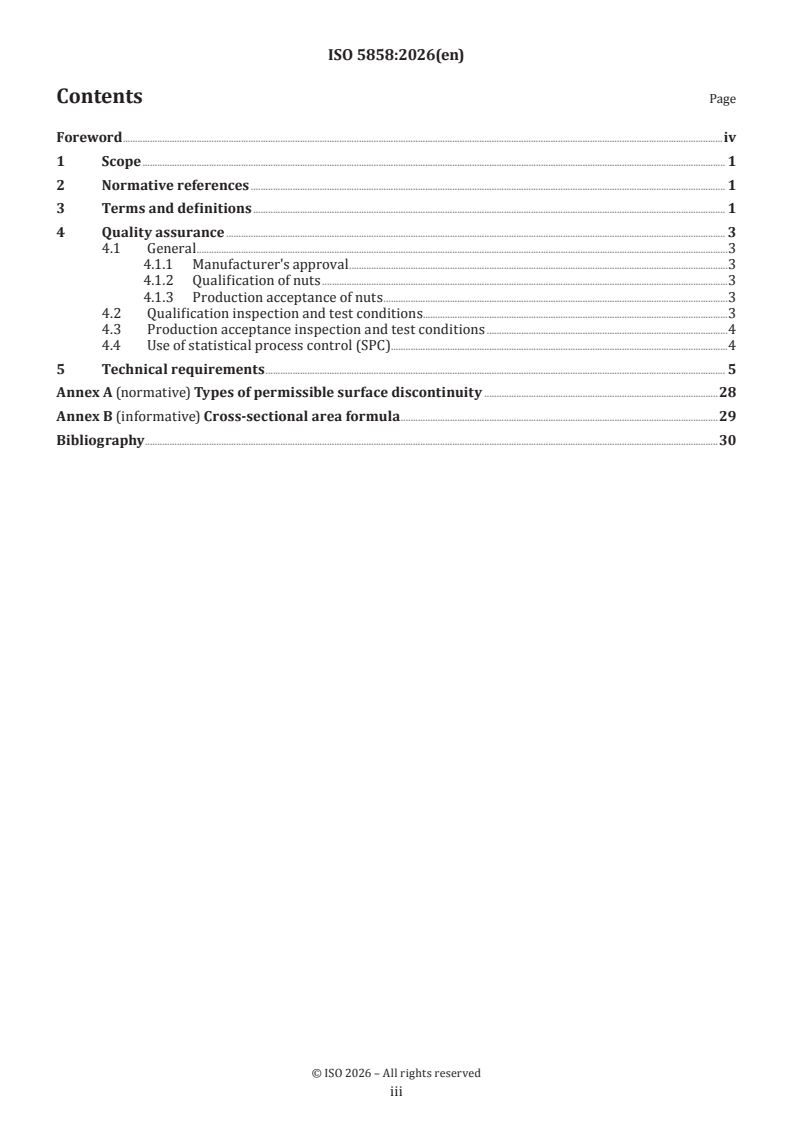

ISO 5858:2026 - Aerospace — Nuts, self-locking, with maximum operating temperature less than or equal to 425 °C — Procurement specification
ISO 5858:2026 - Aéronautique et espace — Écrous auto-freinés dont la température maximale d'utilisation est inférieure ou égale à 425 °C — Spécification d’approvisionnement
ISO 5858:2026 is an International Standard from ISO for metric self-locking nuts with MJ threads used in aerospace construction at temperatures up to 425 °C. It is a procurement specification: it defines the required characteristics, inspection methods and acceptance approach for these nuts when the relevant definition document points to it.
What does ISO 5858:2026 specify?
ISO 5858:2026 specifies the required characteristics for metric self-locking nuts with MJ threads for aerospace use at a maximum operating temperature less than or equal to 425 °C. It applies only when the relevant definition document makes reference to it, so it works as the procurement and acceptance baseline for a defined nut type.
The document is organized into scope, normative references, terms and definitions, quality assurance, technical requirements, and delivery. Table 1 contains the technical requirements and related inspection methods; Table 2 summarizes which characteristics are checked at qualification and production acceptance.
| Annex | What it covers |
|---|---|
| Annex A | Normative types of permissible surface discontinuity and their limits |
| Annex B | Informative cross-sectional area formula used for axial-load calculations |
What are the key requirements of ISO 5858:2026?
ISO 5858:2026 combines quality assurance rules with detailed technical checks on material, geometry, locking function, coatings and delivery. In practice, a supplier has to show that the nuts can be produced consistently, then prove that each batch meets the specified characteristics by inspection and test.
Quality assurance and acceptance
Clause 4 requires the manufacturer to be capable of continuous production that meets the document’s quality requirements. It separates qualification of nuts from production acceptance of nuts, and it makes the manufacturer responsible for the quality of the nuts manufactured.
For qualification, Clause 4.2 says the inspections and tests are carried out on each type and diameter of nut and on 100 nuts selected from a single batch by simple random sampling. For production acceptance, Clause 4.3 says the checks are made on each batch, and destructive and non-destructive inspections may be combined on the same nuts where practical.
Clause 4.4 allows statistical process control (SPC) to replace final systematic sampling if the manufacturer can formally justify the approach and the process has been validated. For a buyer or quality manager, that means SPC is possible, but only with documented control of key characteristics, process capability and audit controls.
Material, coatings and surface condition
Table 1 requires the nut material to match the definition document, and it requires inspection of microstructure, carburization or decarburization, surface discontinuities, hardness and non-magnetism. The practical point is that the standard checks both the internal condition of the metal and visible surface quality, because either can affect strength and service life.
Annex A lists the surface discontinuity types that are allowed, and Table 17 sets the maximum depth for those defects. That matters because some lines, laps or seams may be acceptable if they stay within the defined type and depth limits, but cracks are not permitted.
For surface coatings, Table 1 covers presence, type, thickness, adhesion and corrosion resistance. The document also gives special adhesion tests for molybdenum disulfide [MoS2] and silver coatings at the maximum operating temperature, and a neutral salt spray [NSS] corrosion test in accordance with ISO 9227.
Dimensions, thread fit and wrenching
Clause 5 requires general dimensions, thread conformity, wrench engagement and squareness of the bearing surface to remain within the specified limits. The inspections use gauges and measuring instruments, and the thread checks rely on the relevant MJ thread limits.
For nuts with locking by plastic insert and for all-metal self-locking nuts, the document defines what the threaded GO gauge must be able to do. It also requires that the wrenching feature remains usable after locking, so the nut can still be installed and removed with standard tools.
Locking function and mechanical performance
Clause 6 is the core performance section. It covers axial load capacity, wrenching feature torque, stress embrittlement, torque-out, non-rotation of captive washer, push-out, locking performance at ambient temperature and after exposure to maximum operating temperature, vibration, sealing, swaging and metallic cap retention.
The axial-load tests use loads tied to the nut’s tensile strength class and thread size, with the cross-sectional area calculated from the formula in Annex B. In practice, that means the nut has to survive defined proof-like loading without cracking or losing locking performance.
The locking-related tests are especially important for self-locking nuts. Clause 6 checks self-locking torque, breakaway torque and permanent set, both at ambient temperature and after heat exposure, so the reader can see whether the locking feature still works after service conditions.
Delivery
Clause 7 requires packaging that prevents damage or corrosion during handling, transport and storage, and each package must contain nuts from one production batch only. It also requires clear labelling with the manufacturer’s name or trade mark, complete part number, quantity, production lot number and date of manufacture.
What terms does ISO 5858:2026 define?
- Definition document - The document that sets the nut’s metallurgical, geometrical and functional requirements.
- Finished nut - A nut ready for use, including any specified treatments or surface coatings.
- Production batch - A group of finished nuts made under the same defined production conditions and route.
- Self-locking torque - The torque needed to keep the nut or bolt rotating without axial load, with the locking system fully engaged.
- Seating torque - The tightening torque used to introduce or increase axial load in the assembly.
- Breakaway torque - The torque needed to start unscrewing after the axial load has been removed.
- Wrench torque - The tightening and untightening torques the driving feature must withstand repeatedly without harmful deformation.
- Inspection reliability requirement (IRR) - The minimum acceptable outgoing yield or probability of conformance used in the sampling tables.
Who uses ISO 5858:2026?
ISO 5858:2026 is used by aerospace fastener manufacturers, suppliers, purchasers, quality managers and qualifying bodies. It is also relevant to laboratories and inspection teams that perform qualification, production acceptance and test-method agreement.
In practice, manufacturers use it to plan production controls and release tests. Buyers and approvers use it to specify what evidence is needed before the nuts are accepted for aerospace use. Quality teams use it to decide sampling, validate SPC and manage nonconforming batches.
What changed in ISO 5858:2026 from the previous edition?
ISO 5858:2026 is the third edition and it cancels and replaces ISO 5858:1999. The foreword states that the document has been technically revised.
The main changes listed are:
- updated normative references;
- a changed structure for Table 1;
- new tables for sampling.
Which standards are used with ISO 5858:2026?
ISO 5858:2026 refers to several standards for measurement, test methods and related thread geometry:
- ISO 691 - gives wrench and socket opening tolerances used for wrench engagement checks.
- ISO 1463 - provides the microscopical method for coating-thickness measurement.
- ISO 3452-1 - gives general principles for penetrant testing.
- ISO 3887 - is used for determining decarburization depth.
- ISO 5855-2 - gives MJ thread limit dimensions and supports thread checks and axial-load calculations.
- ISO 7403 - is used for spline-drive wrenching configuration.
- ISO 7481 - provides the test methods used for self-locking nut performance checks.
- ISO 8788 - gives tolerances of form and position for metric nuts.
- ISO 9227 - is used for neutral salt spray corrosion testing.
- ISO 9934 - gives magnetic particle testing methods.
- ISO 21920-3 - is used for surface texture profile specification.
- ASTM E1417 and ASTM E1444 - are alternative penetrant and magnetic particle practices named for agreed use.
- ISO 2859-1, ISO 7870-1, ISO 7870-2, ISO 7870-3 and AS/EN 9138 - are named in the sampling and SPC provisions as supporting references for inspection and control planning.
What does the ISO 5858:2026 document contain?
ISO 5858:2026 contains a full technical requirements table, inspection methods and sampling provisions for aerospace self-locking nuts. Table 1 covers material, coatings, surface condition, marking, dimensions, performance and delivery, while Table 2 summarizes which items are checked at qualification and production acceptance.
It also includes tables for axial loads, torques, locking torque limits and vibration test torque, plus defect classification and sampling plans. The annexes add the permissible surface discontinuity types and the formula used to calculate cross-sectional area for load testing.
For testing and acceptance work, the document is structured so that users can select the relevant inspection path, the method to apply, and the sample size to use for the batch or qualification case.
Relations
- Effective Date
- 15-Feb-2025
Buy Documents
ISO 5858:2026 - Aerospace — Nuts, self-locking, with maximum operating temperature less than or equal to 425 °C — Procurement specification
ISO 5858:2026 - Aéronautique et espace — Écrous auto-freinés dont la température maximale d'utilisation est inférieure ou égale à 425 °C — Spécification d’approvisionnement
Get Certified
Connect with accredited certification bodies for this standard

BUREAU VERITAS Certification Germany
Bureau Veritas certification in Germany.

Element Materials Technology
Materials testing and product certification.

AQMS Ltd.
AQMS provides ISO certification to SMEs across the UK.
Sponsored listings
Frequently Asked Questions
ISO 5858:2026 is a standard published by the International Organization for Standardization (ISO). Its full title is "Aerospace — Nuts, self-locking, with maximum operating temperature less than or equal to 425 °C — Procurement specification". This standard covers: This document specifies the required characteristics for metric self-locking nuts, with MJ threads, for use in aerospace construction at a maximum temperature less than or equal to 425 °C. It is applicable to nuts as defined above, provided that reference is made to this document in the relevant definition document.
This document specifies the required characteristics for metric self-locking nuts, with MJ threads, for use in aerospace construction at a maximum temperature less than or equal to 425 °C. It is applicable to nuts as defined above, provided that reference is made to this document in the relevant definition document.
ISO 5858:2026 is classified under the following ICS (International Classification for Standards) categories: 49.030.30 - Nuts. The ICS classification helps identify the subject area and facilitates finding related standards.
ISO 5858:2026 has the following relationships with other standards: It is inter standard links to ISO 5858:1999. Understanding these relationships helps ensure you are using the most current and applicable version of the standard.
ISO 5858:2026 is available in PDF format for immediate download after purchase. The document can be added to your cart and obtained through the secure checkout process. Digital delivery ensures instant access to the complete standard document.
Standards Content (Sample)
International
Standard
ISO 5858
Third edition
Aerospace — Nuts, self-locking, with
2026-05
maximum operating temperature
less than or equal to 425 °C —
Procurement specification
Aéronautique et espace — Écrous à freinage interne dont la
température maximale d'utilisation est inférieure ou égale à 425
°C — Spécification d'approvisionnement
Reference number
© ISO 2026
All rights reserved. Unless otherwise specified, or required in the context of its implementation, no part of this publication may
be reproduced or utilized otherwise in any form or by any means, electronic or mechanical, including photocopying, or posting on
the internet or an intranet, without prior written permission. Permission can be requested from either ISO at the address below
or ISO’s member body in the country of the requester.
ISO copyright office
CP 401 • Ch. de Blandonnet 8
CH-1214 Vernier, Geneva
Phone: +41 22 749 01 11
Email: copyright@iso.org
Website: www.iso.org
Published in Switzerland
ii
Contents Page
Foreword .iv
1 Scope . 1
2 Normative references . 1
3 Terms and definitions . 1
4 Quality assurance . 3
4.1 General .3
4.1.1 Manufacturer's approval .3
4.1.2 Qualification of nuts .3
4.1.3 Production acceptance of nuts .3
4.2 Qualification inspection and test conditions .3
4.3 Production acceptance inspection and test conditions .4
4.4 Use of statistical process control (SPC) .4
5 Technical requirements . 5
Annex A (normative) Types of permissible surface discontinuity .28
Annex B (informative) Cross-sectional area formula .29
Bibliography .30
iii
Foreword
ISO (the International Organization for Standardization) is a worldwide federation of national standards
bodies (ISO member bodies). The work of preparing International Standards is normally carried out through
ISO technical committees. Each member body interested in a subject for which a technical committee
has been established has the right to be represented on that committee. International organizations,
governmental and non-governmental, in liaison with ISO, also take part in the work. ISO collaborates closely
with the International Electrotechnical Commission (IEC) on all matters of electrotechnical standardization.
The procedures used to develop this document and those intended for its further maintenance are described
in the ISO/IEC Directives, Part 1. In particular, the different approval criteria needed for the different types
of ISO document should be noted. This document was drafted in accordance with the editorial rules of the
ISO/IEC Directives, Part 2 (see www.iso.org/directives).
ISO draws attention to the possibility that the implementation of this document may involve the use of (a)
patent(s). ISO takes no position concerning the evidence, validity or applicability of any claimed patent
rights in respect thereof. As of the date of publication of this document, ISO had not received notice of (a)
patent(s) which may be required to implement this document. However, implementers are cautioned that
this may not represent the latest information, which may be obtained from the patent database available at
www.iso.org/patents. ISO shall not be held responsible for identifying any or all such patent rights.
Any trade name used in this document is information given for the convenience of users and does not
constitute an endorsement.
For an explanation of the voluntary nature of standards, the meaning of ISO specific terms and expressions
related to conformity assessment, as well as information about ISO's adherence to the World Trade
Organization (WTO) principles in the Technical Barriers to Trade (TBT), see www.iso.org/iso/foreword.html.
This document was prepared by Technical Committee ISO/TC 20, Aircraft and space vehicles, Subcommittee
SC 4, Aerospace fastener systems.
This third edition cancels and replaces the second edition (ISO 5858:1999), which has been technically
revised.
The main changes are as follows:
— normative references have been updated;
— the structure of Table 1 has been changed;
— new tables for sampling have been added.
Any feedback or questions on this document should be directed to the user’s national standards body. A
complete listing of these bodies can be found at www.iso.org/members.html.
iv
International Standard ISO 5858:2026(en)
Aerospace — Nuts, self-locking, with maximum operating
temperature less than or equal to 425 °C — Procurement
specification
1 Scope
This document specifies the required characteristics for metric self-locking nuts, with MJ threads, for use in
aerospace construction at a maximum temperature less than or equal to 425 °C.
It is applicable to nuts as defined above, provided that reference is made to this document in the relevant
definition document.
2 Normative references
The following documents are referred to in the text in such a way that some or all of their content constitutes
requirements of this document. For dated references, only the edition cited applies. For undated references,
the latest edition of the referenced document (including any amendments) applies.
ISO 691, Assembly tools for screws and nuts — Wrench and socket openings — Tolerances for general use
ISO 1463, Metallic and oxide coatings — Measurement of coating thickness — Microscopical method
ISO 3452-1, Non-destructive testing — Penetrant testing — Part 1: General principles
ISO 3887, Steels — Determination of the depth of decarburization
ISO 5855-2, Aerospace — MJ threads — Part 2: Limit dimensions for bolts and nuts
ISO 7403, Aerospace — Spline drives — Wrenching configuration — Metric series
ISO 7481, Aerospace — Nuts, self-locking, with maximum operating temperature less than or equal to 425 °C —
Test methods
ISO 8788, Aerospace — Nuts, metric — Tolerances of form and position
ISO 9227, Corrosion tests in artificial atmospheres — Salt spray tests
ISO 9934 , Non-destructive testing — Magnetic particle testing
ISO 21920-3, Geometrical product specifications (GPS) — Surface texture: Profile — Part 3: Specification
operators
ASTM E1417, Standard Practice for Liquid Penetrant Testing
ASTM E1444, Standard Practice for Magnetic Particle Testing
3 Terms and definitions
For the purposes of this document, the following terms and definitions apply.
ISO and IEC maintain terminology databases for use in standardization at the following addresses:
— ISO Online browsing platform: available at https:// www .iso .org/ obp
— IEC Electropedia: available at https:// www .electropedia .org/
3.1
definition document
document specifying all the requirements for nuts, i.e.:
— metallurgical requirements;
— geometrical and dimensional requirements;
— functional requirements (strength and temperature classes)
Note 1 to entry: The definition document may be an International Standard, a national standard, or an in-house
standard or drawing.
3.2
finished nut
nut ready for use, inclusive of any possible treatments or surface coatings, as specified in the definition
document (3.1)
3.3
production batch
quantity of finished nuts (3.2), manufactured using the same process, from a single material cast (single
heat of alloy), having the same number of definitiondocument (3.1), same thread and diameter code, heat
treated together to the same specified condition and produced as one continuous run in the course of the
same production cycle, following the same manufacturing route and having undergone all the relevant heat
treatments and surface treatments
3.4
crack
rupture in the material which can extend in any direction and which can be intercrystalline or
transcrystalline in character
3.5
seam
open surface defect resulting from extension of the metal
3.6
lap
folding over of unwelded metal that can arise when the material is formed (drawing) or in the finished
product (pressing or forging)
3.7
inclusion
non-metallic particle originating from the material manufacturing process
Note 1 to entry: These particles can be isolated or arranged in strings.
3.11
sampling plan
plan according to which one or more samples are taken in order to obtain information and possibly reach a
decision
Note 1 to entry: In this document, each sampling plan specifies the number of nuts to be inspected as a function of the
size of the batch (3.3) and the acceptance number [number of defective items acceptable (Ac)]. See ISO 2859-1.
3.12
simple random sampling
sampling of n items from a population of N items in such a way that all possible combinations of n items have
the same probability of being chosen
3.15
self-locking torque
torque to be applied to the nut or bolt to maintain its movement of rotation in relation to the associated part,
the assembly being under no axial load and the nut-locking system being completely engaged with the bolt
(two pitches minimum protrusion, including the end chamfer)
3.16
seating torque
tightening torque to be applied to the nut or bolt to introduce or to increase the axial load in the assembly
3.18
breakaway torque
torque required to start unscrewing the nut or bolt with respect to the associated part, with the nut-
locking device still fully engaged on the bolt, but after the axial load in the assembly has been removed by
unscrewing half a turn followed by a halt in rotational movement
3.19
wrench torque
tightening and untightening torques which the driving feature of the nut has to withstand repeatedly
without any permanent deformation which would prevent the appropriate wrench from being used or
preclude re-use of the nut
3.20
IRR
initial reliability requirement
inspection reliability requirement
minimum acceptable outgoing yield or probability of conformance
4 Quality assurance
4.1 General
4.1.1 Manufacturer's approval
The manufacturer shall be capable of continuous production of nuts meeting the quality requirements
specified in this document.
4.1.2 Qualification of nuts
The purpose of qualification inspections and tests of nuts is to check that the design and manufacturing
conditions for a nut allow it to satisfy the requirements of this document.
4.1.3 Production acceptance of nuts
The purpose of production acceptance inspection and tests of a nut is to check, as simply as possible, using
a method which is inexpensive but most representative of the actual conditions of use, with the uncertainty
inherent in statistical sampling, that the nuts satisfy the requirements of this document.
Production acceptance inspections and tests shall be carried out by, or under the responsibility of, the
manufacturer.
The manufacturer is responsible for the quality of the nuts manufactured.
4.2 Qualification inspection and test conditions
Qualification inspections and tests (requirements, methods, numbers of nuts) are specified in Table 1. They
shall be carried out on:
— each type and diameter of nut;
— 100 nuts selected from a single batch by simple random sampling.
The test programme can be reduced, or qualification of a nut granted, without inspection or testing; any
such decision shall be based on the results obtained on similar types and diameters of nuts provided that
the design and manufacturing conditions are identical.
The inspections and tests shall be repeated on any nut if the supplier or the manufacturing conditions have
changed.
Qualification inspections and tests are summarized in Table 2.
4.3 Production acceptance inspection and test conditions
Production acceptance inspections and tests (requirements, methods, numbers of nuts) are specified in
Table 1. They shall be carried out on each batch. Nuts from the batch to be tested shall be selected by simple
random sampling.
Each nut may be subjected to several inspections or tests.
The nuts to be subjected to destructive inspections or tests may be those on which non-destructive
inspections or tests have been carried out.
If a more stringent inspection is deemed necessary, all or part of the qualification inspections and tests may
be performed during the production acceptance inspections and testing. In this case, the number of nuts
submitted is the same as that submitted for qualification inspections and tests.
Batches declared unacceptable after the production acceptance inspections and tests shall be submitted
for re-inspection or testing only after either all the defective units have been removed or defects have been
corrected, or both. In this case, the attribute(s) which caused the rejection shall be verified using a sample
of twice the normal size but the maximum number of allowed defective items shall be the same as in the
original inspection.
Production acceptance inspections and tests are summarized in Table 2.
4.4 Use of statistical process control (SPC)
Where a characteristic is obtained by a controlled statistical process, in order to declare conformity of
the characteristic, the manufacturer may refrain from the final systematic sampling provided for in this
document, if he/she is can formally justify this choice by using the standards quoted in it as a basis.
This justification will include the following phases:
— analysis of the product's key characteristics;
— analysis of the risks for each implemented process;
— determination of either the parameters or characteristics, or both, to be respected under SPC;
— determination of the capabilities of each process;
— drawing up an inspection plan and integration in the manufacturing process;
— drawing up of routes and control charts (e.g. ISO 7870-1, ISO 7870-2, ISO 7870-3);
— use of control charts for data consolidation;
— determination of the audits to be run and the control to be carried out to ensure reliability of the device.
To be usable in production, this process shall be validated beforehand by the qualifying body, either during
the qualification phase or a posteriori, according to the case, by analysing the justificatory file and the
results of the qualification inspections such as provided for in Clause 5.
5 Technical requirements
The technical requirements are given in Table 1.
They complement the requirements of all other standards or specifications referenced in the definition
document for the nut.
If there is no International Standard specifying the method to be used, a prior agreement shall be reached
between the user and the manufacturer with respect to the following inspections and tests:
— spectrographic analysis or spectroscopic analysis of the material (Table 1, item-no 111);
— micrographic inspection of the structure of the material (Table 1, item-no 1-2);
— inspection for carburization or decarburization (Table 1, item-no 1-3);
— magnetoscopic or fluorescent inspection for surface discontinuities (Table 1, item-no 1-4);
— magnetic permeability inspection (Table 1, item-no 1-6);
— inspection by chemical reagent to determine type of surface coating (Table 1, item-no 2-2);
— tactile inspection or inspection using a profilometer to determine surface roughness (Table 1, item-
no 3-2).
Table 1 — Technical requirements
Inspection and test Sample
Item-no Characteristic Technical requirement Test category
method size
1 Material
a
1-1 Type The material shall be as Spectrographic analysis Qualification 3
specified in the definition or spectroscopic analysis
document. (method to be agreed upon
between the user and man-
ufacturer).
a
See Clause 4 for applicability conditions.
b
Inspections applicable only to nuts made of steel or steel alloy.
c
Inspection to be carried out before coating of the surface or after removal of the surface coating.
d
Inspection applicable only to nuts made of stainless steel.
e
Inspection applicable only to electrolytic coatings (cadmium, silver, etc.).
f
This inspection may be performed on nuts that have been subjected to the inspection of microstructure (see item no 1-2).
g
Test applicable only to all-metal self-locking wrench nuts.
h
For the qualification testing of all-metal self-locking nuts, the nuts shall be exposed for 6 h to the maximum operating
temperature specified in the definition document before the load is applied.
i
Test applicable only to wrench nuts.
j
Test applicable only to nuts heat-treated to a hardness equal to or greater than 44 HRC.
k
Test applicable only to floating-anchor nuts, gang channel nuts and fixed-anchor nuts, produced in several parts and
assembled by brazing or clinching.
l
Test applicable only to gang channel and anchor nuts, with the exception of corner nuts (see ISO 7481) and of reduced-
series single-lug nuts.
m
For all-metal self-locking nuts made of stainless steel with MoS -type dry-film lubrication, this test shall be carried out
over five cycles in order to avoid any risk of seizing.
n
Test applicable only to nuts of diameter 5 mm, 6 mm, 7 mm, 8 mm, 10 mm and 12 mm (see ISO 7481).
o
Test applicable only to sealing nuts.
p
Test applicable only to clinch nuts.
TTabablele 1 1 ((ccoonnttiinnueuedd))
Inspection and test Sample
Item-no Characteristic Technical requirement Test category
method size
a
1-2 Microstructure Nuts shall be free from Micrographic inspection Qualification 5
cracks. The inclusions of a transverse section
shall not exceed the values (method to be agreed upon
specified in the material between the user and man-
standard, when specified ufacturer).
therein.
a
1-3 Carburization or No area of carburization and Microscopic examina- Qualification 5
b
decarburization no area of total decarburiza- tion in accordance with
tion is permissible. An area the method agreed upon
of partial decarburization between the user and man-
is permissible provided ufacturer or Vickers micro-
that the thickness over the hardness measurement
area is less than or equal to (using a 300 g load) in
0,1 mm. accordance with ISO 3887,
or an equivalent method,
shall be carried out.
b a
1-4 Surface disconti- The types of permissible Magnetoscopic (method Qualification 5
c
nuities surface discontinuity shall to be agreed upon between
be in accordance with the user and manufacturer,
Production Ac- Tables 11
Annex A. The maximum shall in accordance with.
ceptance and 12
depth allowed for these ISO 9934 or ASTM E1444)
discontinuities is given in or penetrant inspection in
Table 17. accordance with ISO 3452-
1 or ASTM E1417.
Nuts shall be free from In the event of any doubt
cracks. arising as to the nature
of the defects detected,
inspect defective nuts at a
magnification of × 10 after
sectioning.
a
See Clause 4 for applicability conditions.
b
Inspections applicable only to nuts made of steel or steel alloy.
c
Inspection to be carried out before coating of the surface or after removal of the surface coating.
d
Inspection applicable only to nuts made of stainless steel.
e
Inspection applicable only to electrolytic coatings (cadmium, silver, etc.).
f
This inspection may be performed on nuts that have been subjected to the inspection of microstructure (see item no 1-2).
g
Test applicable only to all-metal self-locking wrench nuts.
h
For the qualification testing of all-metal self-locking nuts, the nuts shall be exposed for 6 h to the maximum operating
temperature specified in the definition document before the load is applied.
i
Test applicable only to wrench nuts.
j
Test applicable only to nuts heat-treated to a hardness equal to or greater than 44 HRC.
k
Test applicable only to floating-anchor nuts, gang channel nuts and fixed-anchor nuts, produced in several parts and
assembled by brazing or clinching.
l
Test applicable only to gang channel and anchor nuts, with the exception of corner nuts (see ISO 7481) and of reduced-
series single-lug nuts.
m
For all-metal self-locking nuts made of stainless steel with MoS -type dry-film lubrication, this test shall be carried out
over five cycles in order to avoid any risk of seizing.
n
Test applicable only to nuts of diameter 5 mm, 6 mm, 7 mm, 8 mm, 10 mm and 12 mm (see ISO 7481).
o
Test applicable only to sealing nuts.
p
Test applicable only to clinch nuts.
TTabablele 1 1 ((ccoonnttiinnueuedd))
Inspection and test Sample
Item-no Characteristic Technical requirement Test category
method size
a
1-5 Hardness The hardness of the finished In accordance with Qualification 5
nuts shall be within the lim- ISO 7481.
Production accept- Table 16,
its specified in the definition
ance
column B
document for the nut or in
the material standard.
d a
1-6 Non-magnetism The magnetic permeability Method to be agreed upon Qualification 5
of the finished nuts shall be between the user and man-
less than 2 (air = 1) in a mag- ufacturer.
netic field of 15 916 A/m.
2 Surface coating
a
2-1 Presence Surface coating shall be Visual examination. Qualification 100
specified in the definition
Production accept- Tables 11
document applied at the
ance and 13
locations.
e a
2-2 Type Surface coating shall be as Visual examination or Qualification 3
specified in the definition inspection by chemical
Production accept- Table 16,
document. reagent in case of doubt
ance column A
(method to be agreed upon
between the user and man-
ufacturer).
e a
2-3 Thickness The thickness of the surface Device for measuring the Qualification 5
coating shall be within the thickness of surface coat-
Production accept- Table 16,
limits specified in the defini- ings, e.g.
ance column B
tion document.
ISO 1463 for micro graphic
for ISO
If no limits are specified in method or ISO 3497 for
the definition document, the X-Ray method
measurement position is
In case of doubt, micro-
Table 16,
specified as the functional
graphic inspection shall be
Column
surfaces: bearing surface
carried out in accordance
A for ISO
f
and thread surface
with ISO 1463
a
2-4 Adhesion Qualification
a
See Clause 4 for applicability conditions.
b
Inspections applicable only to nuts made of steel or steel alloy.
c
Inspection to be carried out before coating of the surface or after removal of the surface coating.
d
Inspection applicable only to nuts made of stainless steel.
e
Inspection applicable only to electrolytic coatings (cadmium, silver, etc.).
f
This inspection may be performed on nuts that have been subjected to the inspection of microstructure (see item no 1-2).
g
Test applicable only to all-metal self-locking wrench nuts.
h
For the qualification testing of all-metal self-locking nuts, the nuts shall be exposed for 6 h to the maximum operating
temperature specified in the definition document before the load is applied.
i
Test applicable only to wrench nuts.
j
Test applicable only to nuts heat-treated to a hardness equal to or greater than 44 HRC.
k
Test applicable only to floating-anchor nuts, gang channel nuts and fixed-anchor nuts, produced in several parts and
assembled by brazing or clinching.
l
Test applicable only to gang channel and anchor nuts, with the exception of corner nuts (see ISO 7481) and of reduced-
series single-lug nuts.
m
For all-metal self-locking nuts made of stainless steel with MoS -type dry-film lubrication, this test shall be carried out
over five cycles in order to avoid any risk of seizing.
n
Test applicable only to nuts of diameter 5 mm, 6 mm, 7 mm, 8 mm, 10 mm and 12 mm (see ISO 7481).
o
Test applicable only to sealing nuts.
p
Test applicable only to clinch nuts.
TTabablele 1 1 ((ccoonnttiinnueuedd))
Inspection and test Sample
Item-no Characteristic Technical requirement Test category
method size
a) of molybde- There shall be no sign of Heat the nuts to the max- 5
num disulfide flaking, cracking or soften- imum operating tempera-
(MoS2) ing after test. ture specified in the defi-
nition document for 3 h,
then cool the nuts slowly to
ambient temperature.
b) of silver There shall be no sign of Heat the nuts to the
blisters or exfoliation after maximum operating tem-
test. perature specified in the
definition document for
4 h, then rapidly cool the
nuts with compressed air
(at a pressure of 0,3 MPa
to 0,4 MPa) by means of a
nozzle with a diameter of
1,5 mm held close to the
surface of the nuts.
a
2-5 Corrosion resist- The surface coating speci- Neutral salt spray (NSS) Qualification 8
b
ance fied in the definition docu- test shall be carried out in
ment (protective treatment accordance with ISO 9227.
and, possibly, lubrication)
Exposure for 336 h with-
shall ensure effective pro-
out signs of corrosion.
tection against corrosion.
3 Surface condition
a
3-1 Appearance Finished nuts shall be free Visual examination. In Qualification 100
from burrs and bumps. the event of any doubt
Production accept- Tables 11
arising as to the nature
ance and 13
of the defects detected,
inspect defective nuts at a
magnification of × 10 after
sectioning.
a
3-2 Surface Rough- The surface roughness of the In accordance with ISO Qualification 5
c
ness nuts shall be as specified in 21920-3.
the definition document.
Visual examination.
a
See Clause 4 for applicability conditions.
b
Inspections applicable only to nuts made of steel or steel alloy.
c
Inspection to be carried out before coating of the surface or after removal of the surface coating.
d
Inspection applicable only to nuts made of stainless steel.
e
Inspection applicable only to electrolytic coatings (cadmium, silver, etc.).
f
This inspection may be performed on nuts that have been subjected to the inspection of microstructure (see item no 1-2).
g
Test applicable only to all-metal self-locking wrench nuts.
h
For the qualification testing of all-metal self-locking nuts, the nuts shall be exposed for 6 h to the maximum operating
temperature specified in the definition document before the load is applied.
i
Test applicable only to wrench nuts.
j
Test applicable only to nuts heat-treated to a hardness equal to or greater than 44 HRC.
k
Test applicable only to floating-anchor nuts, gang channel nuts and fixed-anchor nuts, produced in several parts and
assembled by brazing or clinching.
l
Test applicable only to gang channel and anchor nuts, with the exception of corner nuts (see ISO 7481) and of reduced-
series single-lug nuts.
m
For all-metal self-locking nuts made of stainless steel with MoS -type dry-film lubrication, this test shall be carried out
over five cycles in order to avoid any risk of seizing.
n
Test applicable only to nuts of diameter 5 mm, 6 mm, 7 mm, 8 mm, 10 mm and 12 mm (see ISO 7481).
o
Test applicable only to sealing nuts.
p
Test applicable only to clinch nuts.
TTabablele 1 1 ((ccoonnttiinnueuedd))
Inspection and test Sample
Item-no Characteristic Technical requirement Test category
method size
a
4 Marking The nuts shall be marked as Visual examination. Qualification 100
specified in the definition
Production accept- Tables 11
document.
ance and 14
5 Dimensions
a
5-1 General dimen- The dimensions and any Suitable limit gauges or Qualification 20
sions deviations in form and po- measuring instruments.
Production accept- Tables 11,14
sition, measured at ambient
ance and 15
temperature, shall be within
the limits specified in the
definition document.
a
5-2 Thread The thread shall be in con- Qualification 20
formity with the definition
Production accept- Tables 11
document.
ance and 13
— Nuts with locking by
plastic insert
The threaded GO gauge shall Threaded GO/NO GO
be capable of being freely gauges.
screwed up to the locking
device
— All-metal selflocking
nuts
The threaded GO gauge shall Threaded GO/NO GO
be capable of being freely gauges.
screwed for at least one
turn.
For nuts with molybdenum Bolt with standard threads
disulfide dry lubrication, a in accordance with
bolt with standard threads ISO 5855-2 shall be used.
shall be capable of being
freely screwed for at least
one turn.
a
See Clause 4 for applicability conditions.
b
Inspections applicable only to nuts made of steel or steel alloy.
c
Inspection to be carried out before coating of the surface or after removal of the surface coating.
d
Inspection applicable only to nuts made of stainless steel.
e
Inspection applicable only to electrolytic coatings (cadmium, silver, etc.).
f
This inspection may be performed on nuts that have been subjected to the inspection of microstructure (see item no 1-2).
g
Test applicable only to all-metal self-locking wrench nuts.
h
For the qualification testing of all-metal self-locking nuts, the nuts shall be exposed for 6 h to the maximum operating
temperature specified in the definition document before the load is applied.
i
Test applicable only to wrench nuts.
j
Test applicable only to nuts heat-treated to a hardness equal to or greater than 44 HRC.
k
Test applicable only to floating-anchor nuts, gang channel nuts and fixed-anchor nuts, produced in several parts and
assembled by brazing or clinching.
l
Test applicable only to gang channel and anchor nuts, with the exception of corner nuts (see ISO 7481) and of reduced-
series single-lug nuts.
m
For all-metal self-locking nuts made of stainless steel with MoS -type dry-film lubrication, this test shall be carried out
over five cycles in order to avoid any risk of seizing.
n
Test applicable only to nuts of diameter 5 mm, 6 mm, 7 mm, 8 mm, 10 mm and 12 mm (see ISO 7481).
o
Test applicable only to sealing nuts.
p
Test applicable only to clinch nuts.
TTabablele 1 1 ((ccoonnttiinnueuedd))
Inspection and test Sample
Item-no Characteristic Technical requirement Test category
method size
a
5-3 Wrench engage- The deformation necessary Female gauge satisfying Qualification 20
g
ment to achieve internal locking the following dimensional
Production accept- Tables 11
shall not prevent a wrench requirements:
ance and 14
from being used.
A female gauge, of identical a) Hexagonal and bihex-
form to the driving feature agonal drive
of the nut being inspected,
Minimum tolerances spec-
shall be capable of being
ified shall be in accordance
freely installed over a length
with ISO 691.
equal to the wrenching
b) Spline drive
height specified in the defi-
nition document.
Maximum material condi-
tion of female wrenching
device shall be in accord-
ance with ISO 7403.
a
5-4 Squareness of Any out-of-squareness of In accordance with Qualification 20
bearing surface the bearing surface, relative ISO 7481.
Production accept- Tables 11
to the thread, shall be
ance to 14
within the limits specified in
ISO 8788.
6 Performance
a
6-1 Axial load The finished nuts shall In accordance with Qualification 8 for 80 %
withstand the axial load ISO 7481. load and 8
specified for their tensile for 100 %
strength class, as laid down load
in the definition document.
Production accept- Table 16,
ance column B
a) 80 % test The nuts shall not display: The load to be applied is
specified in Table 3.
a
See Clause 4 for applicability conditions.
b
Inspections applicable only to nuts made of steel or steel alloy.
c
Inspection to be carried out before coating of the surface or after removal of the surface coating.
d
Inspection applicable only to nuts made of stainless steel.
e
Inspection applicable only to electrolytic coatings (cadmium, silver, etc.).
f
This inspection may be performed on nuts that have been subjected to the inspection of microstructure (see item no 1-2).
g
Test applicable only to all-metal self-locking wrench nuts.
h
For the qualification testing of all-metal self-locking nuts, the nuts shall be exposed for 6 h to the maximum operating
temperature specified in the definition document before the load is applied.
i
Test applicable only to wrench nuts.
j
Test applicable only to nuts heat-treated to a hardness equal to or greater than 44 HRC.
k
Test applicable only to floating-anchor nuts, gang channel nuts and fixed-anchor nuts, produced in several parts and
assembled by brazing or clinching.
l
Test applicable only to gang channel and anchor nuts, with the exception of corner nuts (see ISO 7481) and of reduced-
series single-lug nuts.
m
For all-metal self-locking nuts made of stainless steel with MoS -type dry-film lubrication, this test shall be carried out
over five cycles in order to avoid any risk of seizing.
n
Test applicable only to nuts of diameter 5 mm, 6 mm, 7 mm, 8 mm, 10 mm and 12 mm (see ISO 7481).
o
Test applicable only to sealing nuts.
p
Test applicable only to clinch nuts.
TTabablele 1 1 ((ccoonnttiinnueuedd))
Inspection and test Sample
Item-no Characteristic Technical requirement Test category
method size
— any cracks;
— any permanent set;
— any significant
reduction in their
locking torque.
b) 100 % test The nuts shall not display: The load to be applied is
h
specified in Table 4 .
— any cracks;
— any fractures.
Permanent set and resultant
effects (reduction or disap-
pearance of locking torque)
are permissible.
a
6-2 Wrenching fea- Finished nuts shall with- In accordance with Qualification 3
i
ture (wrench stand the torque specified ISO 7481.
torque) for the tensile strength
The torque shall be as
Production accept- Not appli-
class, as laid down in the
specified in Table 5 and
ance cable
definition document, and
shall be applied 15 times
shall not display any crack
by alternately tightening
or deformation preventing a
and untightening the nut.
standard socket or spanner
from being used.
a
See Clause 4 for applicability conditions.
b
Inspections applicable only to nuts made of steel or steel alloy.
c
Inspection to be carried out before coating of the surface or after removal of the surface coating.
d
Inspection applicable only to nuts made of stainless steel.
e
Inspection applicable only to electrolytic coatings (cadmium, silver, etc.).
f
This inspection may be performed on nuts that have been subjected to the inspection of microstructure (see item no 1-2).
g
Test applicable only to all-metal self-locking wrench nuts.
h
For the qualification testing of all-metal self-locking nuts, the nuts shall be exposed for 6 h to the maximum operating
temperature specified in the definition document before the load is applied.
i
Test applicable only to wrench nuts.
j
Test applicable only to nuts heat-treated to a hardness equal to or greater than 44 HRC.
k
Test applicable only to floating-anchor nuts, gang channel nuts and fixed-anchor nuts, produced in several parts and
assembled by brazing or clinching.
l
Test applicable only to gang channel and anchor nuts, with the exception of corner nuts (see ISO 7481) and of reduced-
series single-lug nuts.
m
For all-metal self-locking nuts made of stainless steel with MoS -type dry-film lubrication, this test shall be carried out
over five cycles in order to avoid any risk of seizing.
n
Test applicable only to nuts of diameter 5 mm, 6 mm, 7 mm, 8 mm, 10 mm and 12 mm (see ISO 7481).
o
Test applicable only to sealing nuts.
p
Test applicable only to clinch nuts.
TTabablele 1 1 ((ccoonnttiinnueuedd))
Inspection and test Sample
Item-no Characteristic Technical requirement Test category
method size
a
6-3 Stress embrittle- Heat treatment and surface In accordance with Qualification 3
j
ment treatment shall not cause ISO 7481.
any embrittlement that
The tightening torque ap-
can prevent the nuts from
plied shall be as specified
withstanding continuously,
in Table 6.
without cracking or ruptur-
The axial load shall be
ing, the axial load specified
applied for 168 h.
for their tensile strength
class, as laid down in the
definition document.
k a
6-4 Torque-out The retention device in the See ISO 7481. Qualification 3
body of the nut shall be
The torque specified in
capable of withstanding the
Table 7 shall be applied in
torque arising during screw-
both directions.
ing, tightening, unscrewing
and untightening, and the
body of the nut shall not
become detached from the
plate, cage or gang channel.
No crack or deformation
shall be present which is
likely to prevent the nut
from being re-used.
a
6-5 Non-rotation of During application of the See ISO 7481. Qualification 5
captive washer captive washer seating
The squeeze torque
torque, the washer shall not
applied shall be equal to
rotate on the bearing plate.
0,5 × the value specified in
The test is not applicable Table 6.
to nuts with a diameter
The seating torque applied
< 4 mm.
shall be the torque speci-
The test shall be carried out fied in Table 6.
on one cycle only.
a
See Clause 4 for applicability conditions.
b
Inspections applicable only to nuts made of steel or steel alloy.
c
Inspection to be carried out before coating of the surface or after removal of the surface coating.
d
Inspection applicable only to nuts made of stainless steel.
e
Inspection applicable only to electrolytic coatings (cadmium, silver, etc.).
f
This inspection may be performed on nuts that have been subjected to the inspection of microstructure (see item no 1-2).
g
Test applicable only to all-metal self-locking wrench nuts.
h
For the qualification testing of all-metal self-locking nuts, the nuts shall be exposed for 6 h to the maximum operating
temperature specified in the definition document before the load is applied.
i
Test applicable only to wrench nuts.
j
Test applicable only to nuts heat-treated to a hardness equal to or greater than 44 HRC.
k
Test applicable only to floating-anchor nuts, gang channel nuts and fixed-anchor nuts, produced in several parts and
assembled by brazing or clinching.
l
Test applicable only to gang channel and anchor nuts, with the exception of corner nuts (see ISO 7481) and of reduced-
series single-lug nuts.
m
For all-metal self-locking nuts made of stainless steel with MoS -type dry-film lubrication, this test shall be carried out
over five cycles in order to avoid any risk of seizing.
n
Test applicable only to nuts of diameter 5 mm, 6 mm, 7 mm, 8 mm, 10 mm and 12 mm (see ISO 7481).
o
Test applicable only to sealing nuts.
p
Test applicable only to clinch nuts.
TTabablele 1 1 ((ccoonnttiinnueuedd))
Inspection and test Sample
Item-no Characteristic Technical requirement Test category
method size
l a
6-6 Push-out Finished nuts shall be capa- See ISO 7481. Qualification 3
ble of withstanding the axial
The load specified in
load which can arise during
Table 8 shall be applied.
screwing without any cracks
appearing.
Any deformation at the
thread axis shall be less
than 0,8 mm and shall not
prevent a standard bolt
being installed over at least
one turn.
6-7 Locking The locking device shall
enable:
— the nuts to be re-used
after several removal
operations;
— correct tensioning
of the bolts when a
normal tightening
torque is applied, and
there shall be no risk of
causing the bolts to fail
under tension.
a
See Clause 4 for applicability conditions.
b
Inspections applicable only to nuts made of steel or steel alloy.
c
Inspection to be carried out before coating of the surface or after removal of the surface coating.
d
Inspection applicable only to nuts made of stainless steel.
e
Inspection applicable only to electrolytic coatings (cadmium, silver, etc.).
f
This inspection may be performed on nuts that have been subjected to the inspection of microstructure (see item no 1-2).
g
Test applicable only to all-metal self-locking wrench nuts.
h
For the qualification testing of all-metal self-locking nuts, the nuts shall be exposed for 6 h to the maximum operating
temperature specified in the definition document before the load is applied.
i
Test applicable only to wrench nuts.
j
Test applicable only to nuts heat-treated to a hardness equal to or greater than 44 HRC.
k
Test applicable only to floating-anchor nuts, gang channel nuts and fixed-anchor nuts, produced in several parts and
assembled by brazing or clinching.
l
Test applicable only to gang channel and anchor nuts, with the exception of corner nuts (see ISO 7481) and of reduced-
series single-lug nuts.
m
For all-metal self-locking nuts made of stainless steel with MoS -type dry-film lubrication, this test shall be carried out
over five cycles in order to avoid any risk of seizing.
n
Test applicable only to nuts of diameter 5 mm, 6 mm, 7 mm, 8 mm, 10 mm and 12 mm (see ISO 7481).
o
Test applicable only to sealing nuts.
p
Test applicable only to clinch nuts.
TTabablele 1 1 ((ccoonnttiinnueuedd))
Inspection and test Sample
Item-no Characteristic Technical requirement Test category
method size
After the test has been
completed, the thread of the
b
...
Norme
internationale
ISO 5858
Troisième édition
Aéronautique et espace — Écrous
2026-05
auto-freinés dont la température
maximale d'utilisation est
inférieure ou égale à 425 °C —
Spécification d’approvisionnement
Aerospace — Nuts, self-locking, with maximum operating
temperature less than or equal to 425 °C — Procurement
specification
Numéro de référence
DOCUMENT PROTÉGÉ PAR COPYRIGHT
© ISO 2026
Tous droits réservés.
La présente publication de l’ISO est protégée par le droit d’auteur et demeure la propriété de l’ISO et/ou de ses concédants de
licence.
Le contenu de la présente publication de l’ISO est fourni sous licence, et n’est pas vendu. Son utilisation est soumise aux conditions
de licence applicables définies par l’ISO, un organisme membre de l’ISO, ou un distributeur tiers agréé.
Sous réserve des besoins liés à sa mise en œuvre ou d’une autorisation expresse prévue aux termes d’une licence distincte, aucune
partie de la présente publication de l’ISO ne peut être reproduite, distribuée, modifiée, utilisée ou mise à disposition sous quelque
forme ou par quelque moyen que ce soit – électronique ou mécanique, y compris la photocopie, la numérisation, l’enregistrement
ou la publication sur des plateformes numériques internes ou externes.
Toute utilisation hors du champ d’application des droits accordés est interdite et peut donner lieu à des poursuites judiciaires.
ISO copyright office
Case postale 401 • CH-1214 Vernier, Genève
Tél.: +41 22 749 01 11
E-mail: copyright@iso.org
Web: www.iso.org
Publié en Suisse
ii
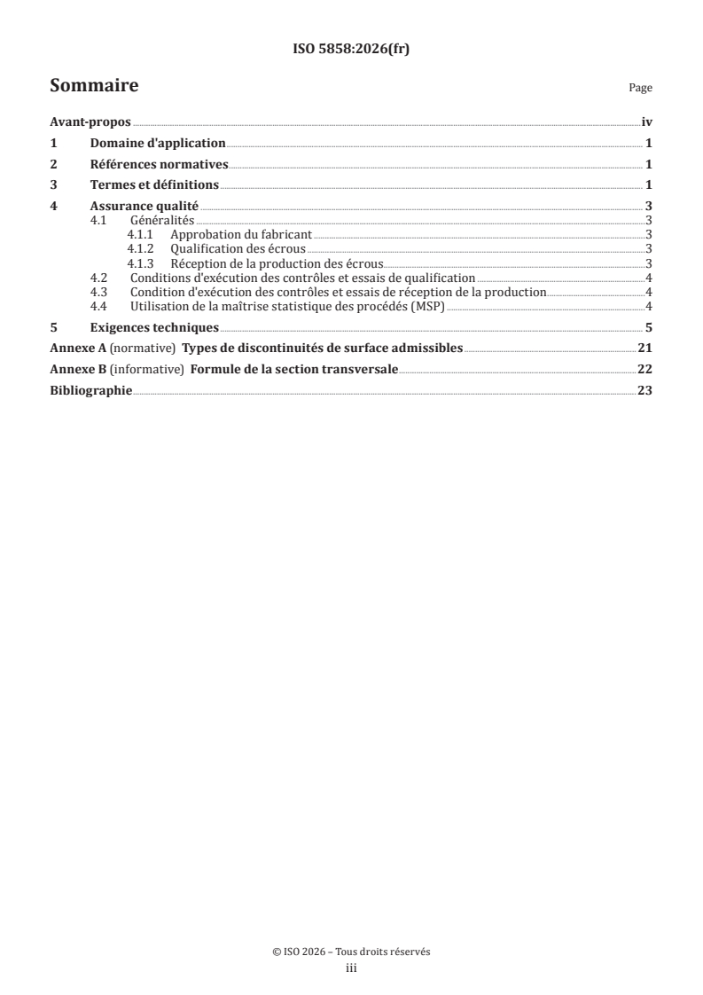
Sommaire Page
Avant-propos .iv
1 Domaine d'application . 1
2 Références normatives . 1
3 Termes et définitions . 1
4 Assurance qualité . 3
4.1 Généralités .3
4.1.1 Approbation du fabricant .3
4.1.2 Qualification des écrous .3
4.1.3 Réception de la production des écrous.3
4.2 Conditions d'exécution des contrôles et essais de qualification .4
4.3 Condition d'exécution des contrôles et essais de réception de la production .4
4.4 Utilisation de la maîtrise statistique des procédés (MSP) .4
5 Exigences techniques . 5
Annexe A (normative) Types de discontinuités de surface admissibles .21
Annexe B (informative) Formule de la section transversale .22
Bibliographie .23
iii
Avant-propos
L'ISO (Organisation internationale de normalisation) est une fédération mondiale d'organismes nationaux
de normalisation (comités membres de l'ISO). L'élaboration des Normes internationales est en général
confiée aux comités techniques de l'ISO. Chaque comité membre intéressé par une étude a le droit de faire
partie du comité technique créé à cet effet. Les organisations internationales, gouvernementales et non
gouvernementales, en liaison avec l'ISO, participent également aux travaux. L'ISO collabore étroitement avec
la Commission électrotechnique internationale (IEC) en ce qui concerne la normalisation électrotechnique.
Les procédures utilisées pour élaborer le présent document et celles destinées à sa mise à jour sont
décrites dans les Directives ISO/IEC, Partie 1. Il convient, en particulier, de prendre note des différents
critères d’approbation requis pour les différents types de documents ISO. Le présent document a
été rédigé conformément aux règles de rédaction données dans les Directives ISO/IEC, Partie 2 (voir
www.iso.org/directives).
L'ISO attire l'attention sur le fait que la mise en application du présent document peut entraîner l'utilisation
d'un ou de plusieurs brevets. L'ISO ne prend pas position quant à la preuve, à la validité et à l'applicabilité de
tout droit de propriété revendiqué à cet égard. À la date de publication du présent document, l'ISO n'avait pas
reçu notification qu'un ou plusieurs brevets pouvaient être nécessaires à sa mise en application. Toutefois,
il y a lieu d'avertir les responsables de la mise en application du présent document que des informations
plus récentes sont susceptibles de figurer dans la base de données de brevets, disponible à l'adresse
www.iso.org/brevets. L'ISO ne saurait être tenue pour responsable de ne pas avoir identifié de tels droits de
propriété et averti de leur existence.
Les appellations commerciales éventuellement mentionnées dans le présent document sont données pour
information, par souci de commodité, à l’intention des utilisateurs et ne sauraient constituer un engagement.
Pour une explication de la nature volontaire des normes, la signification des termes et expressions
spécifiques de l'ISO liés à l'évaluation de la conformité, ou pour toute information au sujet de l'adhésion de
l'ISO aux principes de l’Organisation mondiale du commerce (OMC) concernant les obstacles techniques au
commerce (OTC), voir www.iso.org/avant-propos.
Le présent document a été élaboré par le comité technique ISO/TC 20, Aéronautique et espace, sous-comité
SC 4, Éléments de fixation pour constructions aérospatiales.
Cette troisième édition annule et remplace la deuxième édition (ISO 5858:1999), qui a fait l'objet d'une
révision technique.
Les principaux changements sont les suivants:
— mise à jour des références normatives;
— modification de la structure du Tableau 1;
— ajout de nouveaux tableaux pour l’échantillonnage.
Il convient que l’utilisateur adresse tout retour d’information ou toute question concernant le présent
document à l’organisme national de normalisation de son pays. Une liste exhaustive desdits organismes se
trouve à l'adresse www.iso.org/membres.
iv
Norme internationale ISO 5858:2026(fr)
Aéronautique et espace — Écrous auto-freinés dont la
température maximale d'utilisation est inférieure ou égale à
425 °C — Spécification d’approvisionnement
1 Domaine d'application
Le présent document spécifie les caractéristiques requises pour les écrous auto-freinés, métriques, à
filetage MJ, pour utilisation dans les constructions aérospatiales à des températures maximales inférieures
ou égales à 425 °C.
Il est applicable aux écrous répondant à la définition ci-dessus, à condition qu'il soit référencé dans le
document de définition les concernant.
2 Références normatives
Les documents suivants cités dans le texte constituent, pour tout ou partie de leur contenu, des exigences du
présent document. Pour les références datées, seule l'édition citée s'applique. Pour les références non datées,
la dernière édition du document de référence s’applique (y compris les éventuels amendements).
ISO 691, Outils de manoeuvre pour vis et écrous — Ouvertures de clés et d'embouts de serrage — Tolérances
d'usage courant
ISO 1463, Revêtements métalliques et couches d'oxyde — Mesurage de l'épaisseur de revêtement — Méthode par
coupe micrographique
ISO 3452-1, Essais non destructifs — Examen par ressuage — Partie 1: Principes généraux
ISO 3887, Aciers — Détermination de la profondeur de décarburation
ISO 5855-2, Aéronautique et espace — Filetage MJ — Partie 2: Dimensions limites pour vis et écrous
ISO 7403, Aéronautique et espace — Entraînements cannelés — Série métrique
ISO 7481, Aéronautique et espace — Écrous à freinage interne dont la température maximale d’utilisation est
inférieure ou égale à 425 °C — Méthodes de contrôle et d’essai
ISO 8788, Aéronautique et espace — Écrous métriques — Tolérances de forme et de position
ISO 9227, Essais de corrosion en atmosphères artificielles — Essais aux brouillards salins
ISO 9934, Essais non destructifs — Magnétoscopie
ISO 21920-3, Spécification géométrique des produits (GPS) — État de surface: Méthode du profil — Partie 3:
Opérateurs de spécification
ASTM E1417, Standard Practice for Liquid Penetrant Testing
ASTM E1444, Standard Practice for Magnetic Particle Testing
3 Termes et définitions
Pour les besoins du présent document, les termes et définitions suivants s'appliquent.
L'ISO et l’IEC tiennent à jour des bases de données terminologiques destinées à être utilisées en normalisation,
consultables aux adresses suivantes:
— ISO Online browsing platform: disponible à l'adresse https:// www .iso .org/ obp
— IEC Electropedia: disponible à l'adresse https:// www .electropedia .org/
3.1
document de définition
document spécifiant l'ensemble des exigences pour les écrous, à savoir:
— exigences métallurgiques;
— exigences géométriques et dimensionnelles;
— exigences fonctionnelles (classes de résistance et de température)
Note 1 à l'article: le document de définition peut être une norme internationale, une norme nationale, ou encore une
norme ou un dessin interne.
3.2
écrou fini
écrou prêt à l'emploi, incluant tous les traitements ou revêtements de surface possibles, comme spécifié dans
le document de définition (3.1)
3.3
lot de production
quantité d’écrous finis (3.2), fabriqués selon le même procédé, à partir d’un matériau issu d’une même coulée
(une seule chauffe de l’alliage), ayant le même numéro de document de définition (3.1), les mêmes codes
filetage et diamètre, ayant subi ensemble les mêmes traitements thermiques dans les mêmes conditions
spécifiées et produits au cours de la même campagne continue de fabrication, suivant la même gamme de
fabrication, et ayant subi tous les traitements thermiques et traitements de surface qui conviennent
3.4
crique/fissure
rupture dans le matériau qui peut s’étendre dans n’importe quelle direction et qui peut être de nature
intercristalline ou transcristalline
3.5
strie/rayure
défaut de surface ouvert, résultant de l'étirement du métal
3.6
repli
rabattement de métal non soudé pouvant se produire lors des opérations de formage du matériau (étirage)
ou du produit fini (emboutissage ou forgeage)
3.7
inclusion
particule non métallique ayant pour origine le procédé de fabrication du matériau
Note 1 à l'article: ces particules peuvent être isolées ou réparties en cordons.
3.8
plan d'échantillonnage
plan selon lequel un ou plusieurs échantillons sont prélevés en vue d'obtenir des informations et
éventuellement de prendre une décision
Note 1 à l'article: dans le présent document, chaque plan d'échantillonnage spécifie le nombre d’écrous à contrôler en
fonction de la taille du lot (3.3) et du critère d'acceptation [nombre de défectueux acceptables (Ac)]. Voir l’ISO 2859-1.
3.9
échantillonnage aléatoire simple
mode de prélèvement de n individus dans une population de N individus, tel que toutes les combinaisons
possibles de n individus aient la même probabilité d'être prélevées
3.10
couple de freinage
couple à appliquer à l'écrou ou à la vis pour entretenir son mouvement de rotation par rapport à l'élément
associé, l'assemblage n'étant soumis à aucune charge axiale et le système de freinage de l’écrou étant
entièrement en prise sur la vis (dépassement minimal de deux pas, y compris le chanfrein d'extrémité)
3.11
couple de serrage
couple à appliquer à l'écrou ou à la vis pour introduire ou augmenter la charge axiale dans l'assemblage
3.12
couple de freinage au démarrage après desserrage
couple à appliquer à l'écrou ou à la vis pour provoquer sa mise en rotation par rapport à l'élément associé
dans le sens du dévissage, le système de freinage de l'écrou étant toujours entièrement en prise sur la vis,
mais la charge axiale dans l'assemblage ayant été préalablement supprimée par dévissage d'un demi-tour
suivi de l'arrêt du mouvement de rotation
3.13
couple pour dispositif d'entraînement
couples de serrage et de desserrage auxquels l'élément d'entraînement de l'écrou doit résister de manière
répétée sans subir de déformation permanente qui empêcherait l'utilisation de la clé appropriée ou rendrait
impossible la réutilisation de l'écrou
3.14
IRR (inspection reliability requirement)
exigence de fiabilité initiale
exigence de fiabilité du contrôle
rendement minimal acceptable ou probabilité de conformité
4 Assurance qualité
4.1 Généralités
4.1.1 Approbation du fabricant
Le fabricant doit être capable de produire en continu des écrous répondant aux exigences de qualité
spécifiées dans le présent document.
4.1.2 Qualification des écrous
Les contrôles et essais de qualification des écrous ont pour but de vérifier que la conception et les conditions
de fabrication d'un écrou lui permettent de satisfaire aux exigences du présent document.
4.1.3 Réception de la production des écrous
Les contrôles et essais de réception de la production des écrous ont pour but de vérifier, de la façon la plus
simple, par une méthode peu coûteuse mais la plus représentative des conditions réelles d'emploi, et avec
l'incertitude inhérente à l’échantillonnage statistique, que les écrous satisfont aux exigences du présent
document.
Les contrôles et essais de réception de la production doivent être effectués par le fabricant ou sous sa
responsabilité.
Le fabricant est responsable de la qualité des écrous fabriqués.
4.2 Conditions d'exécution des contrôles et essais de qualification
Les contrôles et essais de qualification (exigences, méthodes, nombre d'écrous) sont spécifiés dans
le Tableau 1. Ils doivent être effectués sur:
— chaque type et chaque diamètre d'écrous;
— 100 écrous prélevés dans un seul lot par échantillonnage aléatoire simple.
Le programme d’essais peut être réduit, ou la qualification d’un écrou être prononcée sans contrôles ou
essais; toute décision en ce sens doit être prise en fonction des résultats obtenus sur d'autres types ou
d'autres diamètres, pourvu que ces écrous aient une conception identique et qu'ils aient été fabriqués dans
les mêmes conditions.
Les contrôles et essais doivent être répétés sur tout écrou si le fournisseur ou les conditions de fabrication
ont changé.
Les contrôles et essais de qualification sont récapitulés dans le Tableau 2.
4.3 Condition d'exécution des contrôles et essais de réception de la production
Les contrôles et essais de réception de la production (exigences, méthodes, nombre d'écrous) sont spécifiés
dans le Tableau 1. Ils doivent être réalisés sur chaque lot. Les écrous du lot à soumettre aux essais doivent
être choisis par échantillonnage aléatoire simple.
Chaque écrou peut être soumis à plusieurs contrôles ou essais.
Les écrous à soumettre à des contrôles ou des essais destructifs peuvent être les mêmes que ceux ayant subi
des contrôles ou des essais non destructifs.
Lorsqu'un contrôle renforcé apparaît nécessaire, tout ou partie des contrôles et essais de qualification
peuvent être effectués au cours des contrôles et essais de réception de la production. Dans ce cas, le nombre
d’écrous soumis à ces contrôles et essais est le même que celui affecté aux contrôles et essais de qualification.
Les lots n'ayant pas satisfait aux contrôles et essais de réception de la production ne doivent être soumis à
un nouveau contrôle ou essai qu'après que toutes les unités défectueuses ont été retirées ou que les défauts
ont été corrigés, ou les deux. Dans ce cas, le ou les attributs ayant entraîné le rejet doivent être vérifiés en
utilisant un échantillon dont l’effectif normal est doublé, mais le nombre maximal de défectueux autorisé
doit rester le même que lors du contrôle initial.
Les contrôles et essais de réception de la production sont récapitulés dans le Tableau 2.
4.4 Utilisation de la maîtrise statistique des procédés (MSP)
Lorsqu’une caractéristique est obtenue par un procédé statistiquement maîtrisé, pour déclarer la conformité
de la caractéristique, le fabricant peut s’abstenir de procéder à l'échantillonnage systématique final prévu
dans le présent document s’il est en mesure de justifier formellement ce choix en s’appuyant sur les normes
qui y sont citées.
Cette justification doit comprendre les phases suivantes:
— analyse des caractéristiques clés du produit;
— analyse des risques pour chaque procédé mis en œuvre;
— détermination des paramètres ou des caractéristiques, ou des deux, à respecter dans le cadre de la MSP;
— détermination des capabilités de chaque procédé;
— élaboration d’un plan de contrôle et intégration dans le processus de fabrication;
— élaboration des gammes et cartes de contrôle (par exemple, ISO 7870-1, ISO 7870-2, ISO 7870-3);
— utilisation des cartes de contrôle pour la consolidation des données;
— détermination des audits à mener et du contrôle à effectuer pour assurer la fiabilité du dispositif.
Pour être utilisable en production, ce dispositif doit être validé au préalable par l'organisme de qualification,
soit lors de la phase de qualification, soit a posteriori selon le cas, en analysant le dossier justificatif et les
résultats des contrôles de qualification tels que prévus à l’Article 5.
5 Exigences techniques
Les exigences techniques sont indiquées dans le Tableau 1.
Elles viennent en complément des exigences figurant dans toutes les autres normes ou spécifications citées
dans le document de définition de l'écrou.
En l'absence de norme internationale spécifiant la méthode à utiliser, un accord préalable doit être conclu
entre l'utilisateur et le fabricant concernant les contrôles et essais suivants:
— analyse spectrographique ou spectroscopique du matériau (Tableau 1, élément 1-1);
— examen micrographique de la structure du matériau (Tableau 1, élément 1-2);
— contrôle de la carburation ou décarburation (Tableau 1, élément 1-3);
— contrôle magnétoscopique ou par ressuage fluorescent des discontinuités de surface (Tableau 1,
élément 1-4);
— contrôle de la perméabilité magnétique (Tableau 1, élément 1-6);
— contrôle au réactif chimique du type de revêtement de surface (Tableau 1, élément 2-2);
— contrôle viso-tactile ou au profilomètre de la rugosité de surface (Tableau 1, élément 3-2).
Tableau 1 — Exigences techniques
Méthode de contrôle et Effectif de
o
N d’élément Caractéristique Exigence technique Catégorie d'essai
d’essai l’échan-tillon
1 Matériau
a
1-1 Type Le matériau doit être tel que Analyse spectrographique ou Qualification 3
spécifié dans le document de spectroscopique (méthode à
définition. définir par accord entre l’utili-
sateur et le fabricant)
a
1-2 Microstructure Les écrous doivent être exempts Examen micrographique d'une Qualification 5
de criques. Les inclusions ne section transversale (méthode
doivent pas dépasser les valeurs à définir par accord entre l’uti-
spécifiées dans la norme du lisateur et le fabricant)
matériau, lorsque celles-ci y sont
indiquées.
a
1-3 Carburation ou Aucune zone de carburation ni Un examen microscopique en Qualification 5
b
décarburation aucune zone de décarburation conformité avec la méthode
totale n'est autorisée. Une zone convenue entre l'utilisateur et
de décarburation partielle est le fabricant ou une mesure de
admissible à condition que son microdureté Vickers (avec une
épaisseur soit inférieure ou égale charge de 300 g) en confor-
à 0,1 mm. mité avec l’ISO 3887, ou une
méthode équivalente, doit être
effectué(e).
a
1-4 Discontinuités de Les types de discontinuités de Contrôle magnétoscopi- Qualification 5
c b
surface surface admissibles doivent être que (méthode à définir par
en conformité avec l'Annexe A. La accord entre l’utilisateur et le
Réception de la Tableau 11 et
profondeur maximale autorisée fabricant, en conformité avec
production Tableau 12
pour ces discontinuités est indi- l’ISO 9934 ou l’ASTM E1444),
quée dans le Tableau 17. ou par ressuage en confor-
mité avec l’ISO 3452-1 ou
l’ASTM E1417
TTabableleaauu 1 1 ((ssuuiitte)e)
Méthode de contrôle et Effectif de
o
N d’élément Caractéristique Exigence technique Catégorie d'essai
d’essai l’échan-tillon
Les écrous doivent être exempts En cas de doute sur la nature
de criques. des défauts constatés, procé-
der à un contrôle des écrous
défectueux à un grossissement
de × 10 après les avoir section-
nés.
a
1-5 Dureté La dureté des écrous finis doit En conformité avec l’ISO 7481 Qualification 5
être comprise dans les limites
Réception de la Tableau 16,
spécifiées dans le document de
production colonne B
définition de l'écrou ou dans la
norme de matériau.
d a
1-6 Amagnétisme La perméabilité magnétique des Méthode à définir par accord Qualification 5
écrous finis doit être inférieure entre l’utilisateur et le fabricant
à 2 (air = 1) dans un champ
magnétique de 15 916 A/m.
2 Revêtement de surface
a
2-1 Présence Le revêtement de surface doit Examen visuel Qualification 100
être appliqué aux emplacements
Réception de la Tableau 11 et
spécifiés dans le document de
production Tableau 13
définition.
e a
2-2 Type Le revêtement de surface doit Examen visuel ou contrôle Qualification 3
être tel que spécifié dans le docu- au réactif chimique en cas de
Réception de la Tableau 16,
ment de définition. doute (méthode à définir par
production colonne A
accord entre l’utilisateur et le
fabricant)
e a
2-3 Épaisseur L'épaisseur du revêtement de Dispositif de mesure de Qualification 5
surface doit être comprise dans l'épaisseur des revêtements de
Réception de la Tableau 16,
les limites spécifiées dans le surface, par exemple ISO 1463
production colonne B pour
document de définition. pour l’examen micrographique
l’ISO 1463
ou ISO 3497 pour les rayons X
Si aucune limite n’est spécifiée
dans le document de définition, En cas de doute, un examen
Tableau 16,co-
l’emplacement des mesures se micrographique doit être
lonne A pour
situe sur les surfaces fonction- réalisé en conformité avec
f
l’ISO 3497
nelles: face d’appui et surface du l’ISO 1463.
filetage.
a
2-4 Adhérence Qualification
a) du bisulfure de Aucune trace d'écaillage, de fissu- Chauffer les écrous à la tempé- 5
molybdène ration ou de ramollissement ne rature maximale d'utilisation
(MoS ) doit apparaître après l'essai. spécifiée dans le document de
définition pendant 3 h, puis les
laisser refroidir lentement à
température ambiante.
b) de l’argent Aucune trace de cloques ni Chauffer les écrous à la tempé-
d’exfoliation ne doit apparaître rature maximale d'utilisation
après l'essai. spécifiée dans le document de
définition pendant 4 h, puis
les refroidir rapidement à l'air
comprimé (à une pression de
0,3 MPa à 0,4 MPa) à l'aide
d'une buse d'un diamètre de
1,5 mm tenue à proximité de
leur surface.
a
2-5 Résistance à la cor- Le revêtement de surface spécifié L’essai au brouillard salin Qualification 8
b
rosion dans le document de définition neutre (NSS, neutral salt spray)
(traitement de protection et, doit être effectué en conformité
éventuellement, lubrification) avec l’ISO 9227.
doit assurer une protection effi-
Exposition pendant 336 h sans
cace contre la corrosion.
traces de corrosion
3 État de surface
a
3-1 Aspect Les écrous finis doivent être Examen visuel. En cas de Qualification 100
exempts de bavures et d'aspé- doute sur la nature des défauts
Réception de la Tableau 11 et
rités. constatés, procéder à un
production Tableau 13
contrôle des écrous défectueux
à un grossissement de × 10
après les avoir sectionnés.
c a
3-2 Rugosité de surface La rugosité de surface des écrous En conformité avec l’ISO 21920- Qualification 5
doit être telle que spécifiée dans 3
le document de définition.
Examen visuel
TTabableleaauu 1 1 ((ssuuiitte)e)
Méthode de contrôle et Effectif de
o
N d’élément Caractéristique Exigence technique Catégorie d'essai
d’essai l’échan-tillon
a
4 Marquage Les écrous doivent être marqués Examen visuel Qualification 100
comme spécifié dans le document
Réception de la Tableau 11 et
de définition.
production Tableau 14
5 Dimensions
a
5-1 Dimensions géné- Les dimensions et tous écarts de Calibres à limites ou instru- Qualification 20
rales forme et de position, mesurés à ments de mesure adaptés
Réception de la Tableau 11,
température ambiante, doivent se
production Tableau 14 et
situer dans les limites spécifiées
Tableau 15
dans le document de définition.
a
5-2 Filetage Le filetage doit être en conformi- Qualification 20
té avec le document de définition.
Réception de la Tableau 11 et
production Tableau 13
— Écrous à freinage par
insert en plastique
Le calibre fileté «GO» doit pou- Calibres filetés GO/NO GO
voir être vissé librement jusqu'au
dispositif de freinage.
— Écrous auto-freinés
entièrement métalliques
Le calibre fileté «GO» doit pou- Calibres filetés GO/NO GO
voir être vissé librement sur au
moins un tour.
Pour les écrous comportant une Une vis à filetage standard en
lubrification à film sec à base de conformité avec l’ISO 5855-2
bisulfure de molybdène, une vis doit être utilisée.
à filetage standard doit pouvoir
être vissée librement sur au
moins un tour.
g a
5-3 Prise à la clé La déformation nécessaire pour Calibre femelle répondant aux Qualification 20
obtenir le freinage interne ne exigences dimensionnelles
Réception de la Tableau 11 et
doit pas empêcher l'utilisation suivantes:
production Tableau 14
d'une clé.
Un calibre femelle, de forme a) Entraînement hexagonal
identique à l'élément d'entraîne- et bihexagonal
ment de l'écrou à contrôler, doit
Les tolérances minimales
pouvoir être monté librement sur
spécifiées doivent être en
une longueur égale à la hauteur
conformité avec l’ISO 691.
de prise à la clé spécifiée dans le
document de définition.
b) Entraînement cannelé
L'état maximal du matériau du
dispositif de serrage femelle
doit être en conformité avec
l’ISO 7403.
a
5-4 Équerrage de la face Tout faux équerrage de la face En conformité avec l’ISO 7481 Qualification 20
d'appui d'appui par rapport au filetage
Réception de la Tableau 11 à
doit être compris dans les limites
production Tableau 14
spécifiées dans l’ISO 8788.
6 Performances
a
6-1 Charge axia
...