

ISO 19085-22:2026
(Main)Woodworking machines — Safety — Part 22: Single blade automatic and semi-automatic up-cutting cross-cut sawing machines
- Abstract
This document specifies the safety requirements and measures for single blade automatic and semi-automatic up-cutting cross-cut sawing machines, capable of continuous production use, hereinafter referred to also as “machines”. The machines are designed to cut solid wood, material with similar physical characteristics to wood, and: aluminium profiles also filled or composed with plastic or foam or rubber based insulating materials; composite materials, with core consisting of, for example, polyurethane or mineral material, laminated with light alloy; polymer‐matrix composite materials and reinforced with thermoplastic or thermoset or elastomeric materials; fibreglass; composite bars made from the materials listed above. This document deals with all significant hazards, hazardous situations or hazardous events, listed in Annex A, relevant to the machines, when it is used as intended and under conditions of misuse which are reasonably foreseeable by the manufacturer. This document is also applicable to the other life cycle phases of the machines: transport, assembly, adjustment, maintenance, dismantling and scrapping. Any workpiece positioning equipment fitted to the machine is included in this document. This document does not deal with any hazards related to single machine being used in combination with any other machine as part of a line. This document does not apply to: machines designed for cross cutting logs; machines intended for use in potentially explosive atmosphere; machines manufactured prior to publication of this document.
- Status
- Published
- Publication Date
- 16-Nov-2026
- Technical Committee
- ISO/TC 39/SC 4 - Woodworking machines
- Drafting Committee
- ISO/TC 39/SC 4 - Woodworking machines
- Current Stage
- 6060 - International Standard published
- Start Date
- 17-Nov-2026
- Completion Date
- 17-Nov-2026
Buy Documents
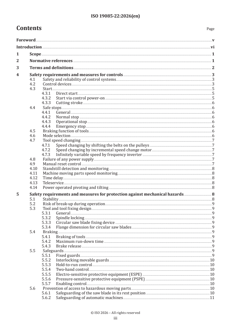
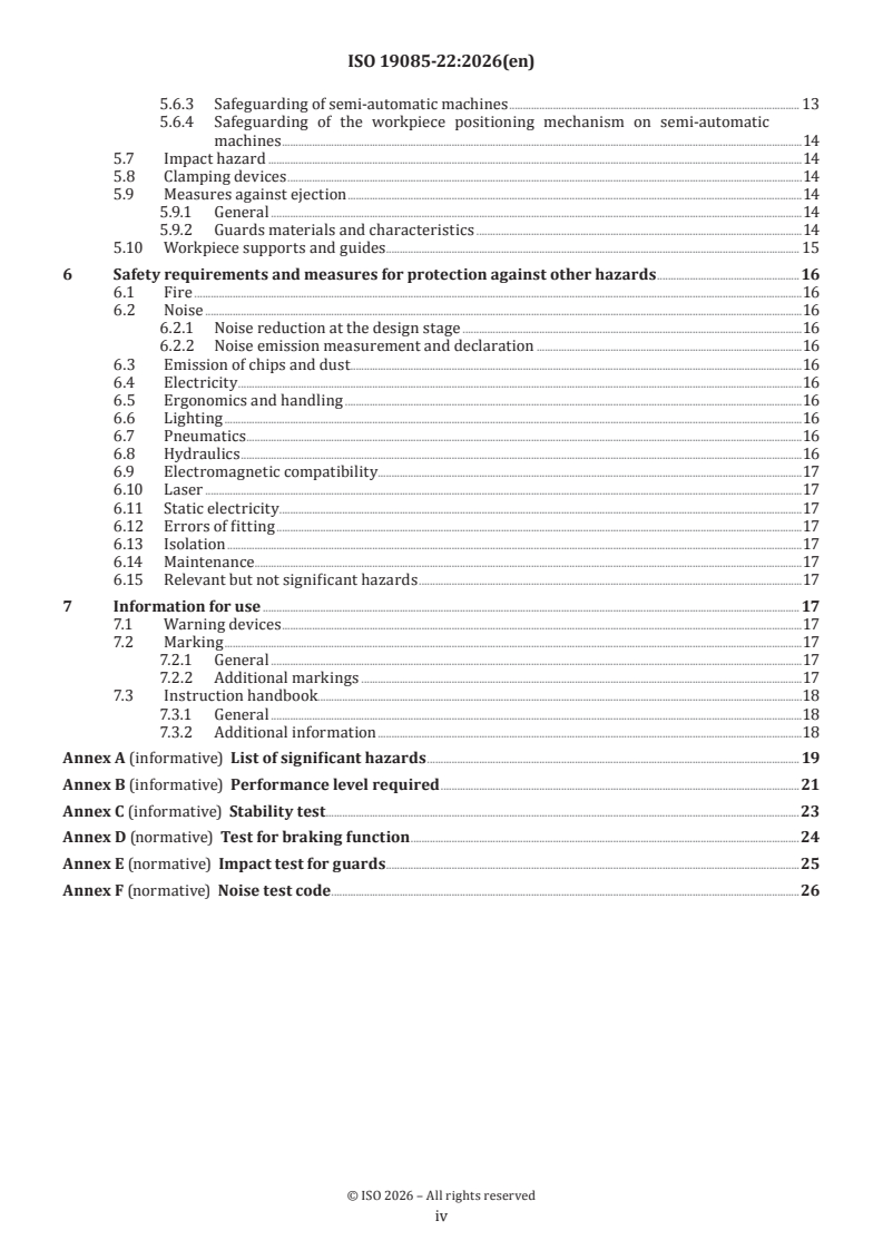
ISO 19085-22:2026 - Woodworking machines — Safety — Part 22: Single blade automatic and semi-automatic up-cutting cross-cut sawing machines
ISO 19085-22:2026 - Machines à bois — Sécurité — Partie 22: Tronçonneuses monolames automatiques et semi-automatiques à coupe ascendante
ISO 19085-22:2026 is an International Standard from ISO for the safety of single blade automatic and semi-automatic up-cutting cross-cut sawing machines used in woodworking. It specifies safety requirements and protective measures for the machine itself, its workpiece positioning equipment, and its life cycle phases from transport through scrapping.
This is a type-C machinery safety standard intended to be used together with ISO 19085-1:2021. For designers, manufacturers, suppliers, importers, buyers and safety staff, it shows what the machine must include, how key safety functions are controlled, and what tests and information for use are needed.
What does ISO 19085-22:2026 specify?
ISO 19085-22:2026 specifies safety requirements for single blade automatic and semi-automatic up-cutting cross-cut sawing machines capable of continuous production use. It covers machines for solid wood, wood-like materials, and several specified composite and aluminium-based materials.
The scope also covers hazards identified as significant in Annex A, when the machine is used as intended and under reasonably foreseeable misuse. It applies across transport, assembly, adjustment, maintenance, dismantling and scrapping, and includes any fitted workpiece positioning equipment.
The document excludes hazards from using one machine in combination with other machines as part of a line. It also excludes machines for cross cutting logs, machines intended for potentially explosive atmospheres, and machines made before publication.
The document is organized into the following main clauses and annexes:
| Part | What it covers |
|---|---|
| Clause 4 | Safety requirements and measures for controls |
| Clause 5 | Safety requirements and measures for mechanical hazards |
| Clause 6 | Safety requirements and measures for other hazards |
| Clause 7 | Information for use |
| Annex A | List of significant hazards |
| Annex B | Performance level required |
| Annex C | Stability test |
| Annex D | Test for braking function |
| Annex E | Impact test for guards |
| Annex F | Noise test code |
What are the key requirements of ISO 19085-22:2026?
ISO 19085-22:2026 focuses on how the machine is controlled, guarded, stopped, and marked so that the saw unit, workpiece feed, clamping, and moving guards do not expose the operator to hazardous movement. In practice, it tells the manufacturer where safety-related control devices go, which movements must be interlocked, and which tests verify the design.
Controls, start and stop functions
Clause 4 requires the main control devices for saw spindle start, normal stop, mode selection where fitted, and integrated feed to be on the machine or on a separate fixed or mobile panel with a view of the machine. This matters because the operator must be able to see the saw area while controlling the machine.
The cutting stroke may only start after saw rotation and powered clamping, if fitted, have been initiated. For semi-automatic machines, each cutting stroke is started by a hand-operated control device. The stopping sequence must first return the saw blade and then stop the tool drive, which reduces the chance of exposure to a moving blade.
Clause 4 also requires mode selection on machines that work as both semi-automatic and automatic. Mode change must not start movement and must bring the machine to a safe stop. That helps avoid confusion when switching between manual and automatic production.
Safety-related control performance
Annex B summarizes the required performance level (PL) for the safety functions in Clauses 4 and 5. Many of the main interlocks, stop functions and guard-related functions require PL c. This tells the designer the reliability target for the safety-related parts of the control system (SRP/CS).
The standard also points to IEC 61800-5-2 for safe limited speed in the case of infinitely variable speed drives, and to IEC 60204-1 for electrical requirements. For a buyer or integrator, this means the electrical and functional safety design must be assessed as part of the machine package, not as an afterthought.
Guarding and access prevention
Clause 5 requires fixed guards and, in many cases, interlocking movable guards to prevent access to the saw blade and other hazardous moving parts. For the saw blade in its rest position, access is prevented by fixed guards with openings limited according to ISO 13857, with specific exceptions for the table slot.
For automatic machines, access to the cutting area must be prevented from any direction by fixed guards and interlocking movable guards, except at loading and unloading openings. Those openings are controlled by workpiece supports plus either extended guards or stationary laser scanners or safety mats. This is important because automatic machines can expose operators at infeed and outfeed points.
Semi-automatic machines may use several guarding arrangements, but the cutting stroke must be controlled so that clamping and protective positions are established before movement. The workpiece positioning mechanism on semi-automatic machines, and automatic machines used in semi-automatic mode, must be controlled by hold-to-run. That reduces the risk of unexpected movement during manual handling.
Braking, stability and tool-related hazards
Clause 5 also covers braking and tool safety. The standard gives maximum run-down times based on saw blade diameter and requires a braking-function test in Annex D. For users, this means the saw must stop quickly enough for safe access and safe changeover.
For larger saw blades, the flange dimension is addressed, and the standard sets a special lower limit for saw blades above 450 mm diameter. Clause 5 also addresses stability and break-up during operation, including a requirement to line the table slot and fence slot with easily machinable material.
Noise, chips, dust and other hazards
Clause 6 covers noise, chips and dust, electricity, ergonomics, pneumatics, hydraulics, electromagnetic compatibility, laser, static electricity, isolation, maintenance, and other relevant hazards. Noise emission measurement and declaration use the noise test code in Annex F.
The machine must also enclose the part of the saw blade below the table with a capture device having an extraction outlet. This matters because dust and chip control affects both operator health and shop housekeeping.
Marking and handbook information
Clause 7 requires marking and instruction handbook content that supports safe use. The machine must be marked with the maximum and minimum saw blade diameters, bore diameter, and, where relevant, a label showing the monitored spindle speed and the permitted tool speed.
The handbook must include details such as extension table characteristics if user-built, replacement of the table insert when damaged, weekly checking of the slot in the enclosure, and the operator positions for loading, unloading and control. That information is needed so the machine can be installed and used as intended.
What terms does ISO 19085-22:2026 define?
- Up-cutting cross-cut sawing machine - a machine with a mechanically fed single saw blade that sits below the workpiece support in rest position and moves upward for cutting.
- Semi-automatic machine - a machine where the workpiece is positioned manually or by manually controlled power-operated positioning, and each cutting stroke is started manually.
- Automatic machine - a machine where the workpiece is positioned automatically and the cutting cycle starts automatically for preset lengths and angles.
- Rest position - the position where the saw unit is below the workpiece support and where the cutting stroke starts and ends.
- Cutting stroke - the feed movement of the saw unit for the cut, followed by its return to rest position.
- Cutting cycle - the automatic sequence of positioning, pivoting, tilting and cutting stroke on automatic machines.
- Initiation control - a control that, when actuated, enables power to specific machine actuators.
- Workpiece positioning mechanism - the mechanism that pushes the workpiece into the intended position for cutting.
Who uses ISO 19085-22:2026?
ISO 19085-22:2026 is used by machine designers, manufacturers, suppliers and importers who design, build and place these saws on the market. It is also used by machine users and employers who need to select, install, operate and maintain the equipment safely.
Health and safety bodies, regulators, accident prevention organizations and market surveillance authorities use it to assess whether a machine’s safety measures match the intended application. Service providers and maintenance personnel use it for safe adjustment, inspection and repair work.
Which standards are used with ISO 19085-22:2026?
- ISO 12100:2010 - provides the general principles for risk assessment and risk reduction, and supplies shared definitions used by the document.
- ISO 13857:2019 - provides safety distances for preventing upper and lower limbs from reaching hazard zones.
- ISO 19085-1:2021 - gives the common woodworking-machine safety requirements that this part uses, replaces or adds to.
- IEC 60204-1:2016 - provides general electrical requirements for machine equipment.
- IEC 61800-5-2:2016 - provides functional safety requirements for adjustable speed power drive systems, including safely-limited speed.
What does the ISO 19085-22:2026 document contain?
The document contains detailed clauses on control systems, start and stop logic, mode selection, speed monitoring, pivoting and tilting, guarding, access prevention, braking, noise, dust extraction, ergonomics and marking. It also contains figures showing machine layout and guard placement, which help designers position controls and protective devices correctly.
Annex A lists significant hazards and links them to the clauses that address them. Annex B summarizes the required performance levels for safety functions, while Annex D, E and F provide the braking test, guard impact test and noise test code used for verification and declaration.
For testing and certification work, Annex F gives operating conditions, microphone position and test material for noise measurement, while Annex D and Annex E support validation of braking and guard strength. For design reviews and audits, the clause structure shows where the required safety measures sit in the machine life cycle and which parts of ISO 19085-1:2021 are carried forward or replaced.
Relations
- Effective Date
- 12-Feb-2026
- Effective Date
- 20-Apr-2024
Buy Documents
ISO 19085-22:2026 - Woodworking machines — Safety — Part 22: Single blade automatic and semi-automatic up-cutting cross-cut sawing machines
ISO 19085-22:2026 - Machines à bois — Sécurité — Partie 22: Tronçonneuses monolames automatiques et semi-automatiques à coupe ascendante
Get Certified
Connect with accredited certification bodies for this standard

CIS Institut d.o.o.
Personal Protective Equipment (PPE) certification body. Notified Body NB-2890 for EU Regulation 2016/425 PPE.
Gozdarski inštitut Slovenije
Slovenian Forestry Institute. Forest management certification support, timber testing.

Kiwa BDA Testing
Building and construction product certification.
Sponsored listings
Frequently Asked Questions
ISO 19085-22:2026 is a standard published by the International Organization for Standardization (ISO). Its full title is "Woodworking machines — Safety — Part 22: Single blade automatic and semi-automatic up-cutting cross-cut sawing machines". This standard covers: This document specifies the safety requirements and measures for single blade automatic and semi-automatic up-cutting cross-cut sawing machines, capable of continuous production use, hereinafter referred to also as “machines”. The machines are designed to cut solid wood, material with similar physical characteristics to wood, and: aluminium profiles also filled or composed with plastic or foam or rubber based insulating materials; composite materials, with core consisting of, for example, polyurethane or mineral material, laminated with light alloy; polymer‐matrix composite materials and reinforced with thermoplastic or thermoset or elastomeric materials; fibreglass; composite bars made from the materials listed above. This document deals with all significant hazards, hazardous situations or hazardous events, listed in Annex A, relevant to the machines, when it is used as intended and under conditions of misuse which are reasonably foreseeable by the manufacturer. This document is also applicable to the other life cycle phases of the machines: transport, assembly, adjustment, maintenance, dismantling and scrapping. Any workpiece positioning equipment fitted to the machine is included in this document. This document does not deal with any hazards related to single machine being used in combination with any other machine as part of a line. This document does not apply to: machines designed for cross cutting logs; machines intended for use in potentially explosive atmosphere; machines manufactured prior to publication of this document.
This document specifies the safety requirements and measures for single blade automatic and semi-automatic up-cutting cross-cut sawing machines, capable of continuous production use, hereinafter referred to also as “machines”. The machines are designed to cut solid wood, material with similar physical characteristics to wood, and: aluminium profiles also filled or composed with plastic or foam or rubber based insulating materials; composite materials, with core consisting of, for example, polyurethane or mineral material, laminated with light alloy; polymer‐matrix composite materials and reinforced with thermoplastic or thermoset or elastomeric materials; fibreglass; composite bars made from the materials listed above. This document deals with all significant hazards, hazardous situations or hazardous events, listed in Annex A, relevant to the machines, when it is used as intended and under conditions of misuse which are reasonably foreseeable by the manufacturer. This document is also applicable to the other life cycle phases of the machines: transport, assembly, adjustment, maintenance, dismantling and scrapping. Any workpiece positioning equipment fitted to the machine is included in this document. This document does not deal with any hazards related to single machine being used in combination with any other machine as part of a line. This document does not apply to: machines designed for cross cutting logs; machines intended for use in potentially explosive atmosphere; machines manufactured prior to publication of this document.
ISO 19085-22:2026 is classified under the following ICS (International Classification for Standards) categories: 13.110 - Safety of machinery; 79.120.10 - Woodworking machines. The ICS classification helps identify the subject area and facilitates finding related standards.
ISO 19085-22:2026 has the following relationships with other standards: It is inter standard links to FprEN ISO 19085-22, ISO 15877-2:2009/Amd 2:2020. Understanding these relationships helps ensure you are using the most current and applicable version of the standard.
ISO 19085-22:2026 is available in PDF format for immediate download after purchase. The document can be added to your cart and obtained through the secure checkout process. Digital delivery ensures instant access to the complete standard document.
Standards Content (Sample)
International
Standard
ISO 19085-22
First edition
Woodworking machines — Safety —
2026-11
Part 22:
Single blade automatic and semi-
automatic up-cutting cross-cut
sawing machines
Machines à bois — Sécurité —
Partie 22: Tronçonneuses monolames automatiques et semi-
automatiques à coupe ascendante
Reference number
© ISO 2026
All rights reserved.
This ISO publication is protected by copyright and is owned by ISO and/or its licensors.
The content of this ISO publication is provided under licence, not sold. Use is subject to the applicable licence terms issued by ISO,
an ISO member body, or an authorized third-party distributor.
Except as required for implementation or expressly permitted by a separate licence, no part of this ISO publication may be
reproduced, distributed, modified, used, or made available in any form or by any means – electronic or mechanical, including
photocopying, scanning, recording, or posting on internal or external digital platforms.
Any use beyond the scope of the granted rights is prohibited and may result in legal action.
ISO copyright office
CP 401 • CH-1214 Vernier, Geneva
Phone: +41 22 749 01 11
Email: copyright@iso.org
Website: www.iso.org
Published in Switzerland
ii
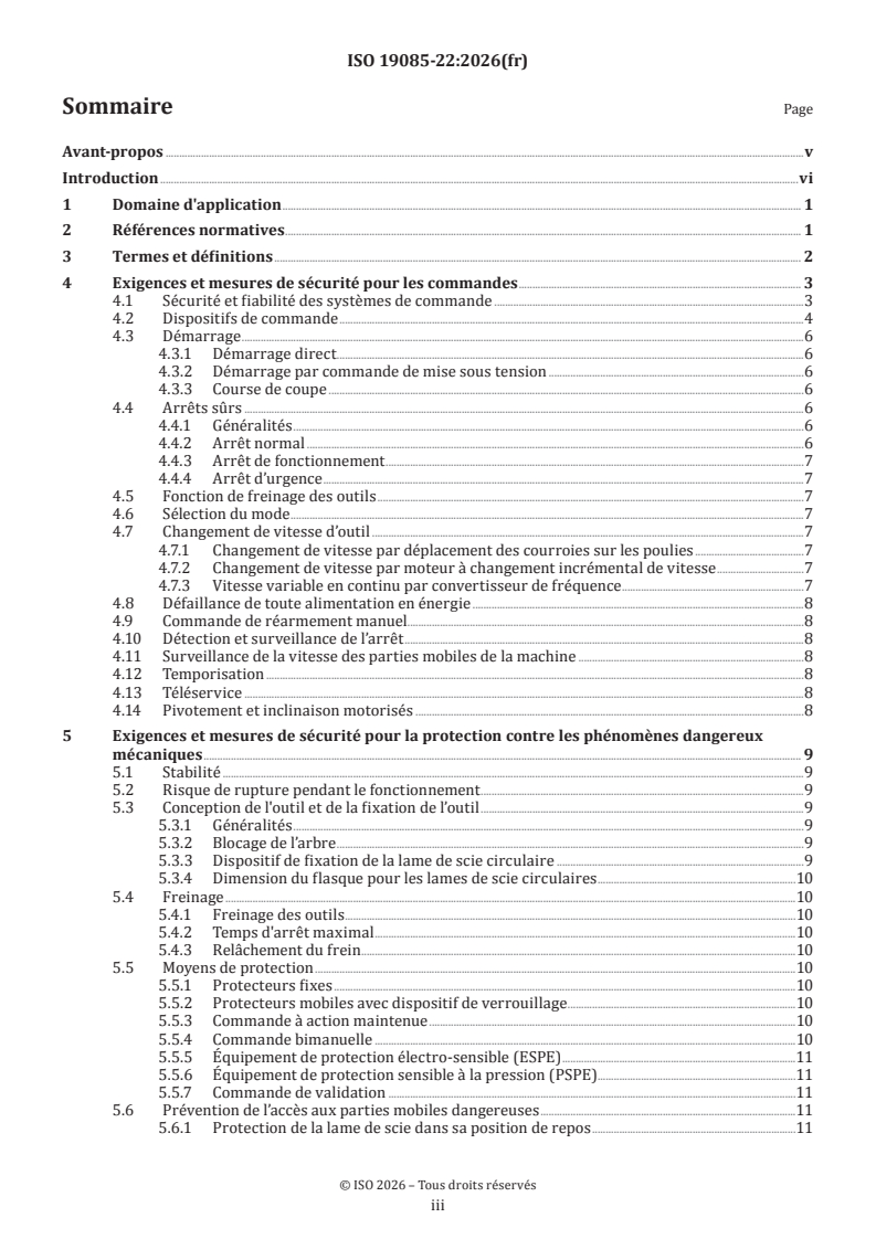
Contents Page
Foreword .v
Introduction .vi
1 Scope . 1
2 Normative references . 1
3 Terms and definitions . 2
4 Safety requirements and measures for controls . 3
4.1 Safety and reliability of control systems.3
4.2 Control devices .3
4.3 Start .5
4.3.1 Direct start .5
4.3.2 Start via control power-on .5
4.3.3 Cutting stroke .6
4.4 Safe stops .6
4.4.1 General .6
4.4.2 Normal stop .6
4.4.3 Operational stop .6
4.4.4 Emergency stop .6
4.5 Braking function of tools .6
4.6 Mode selection .6
4.7 Tool speed changing .7
4.7.1 Speed changing by shifting the belts on the pulleys .7
4.7.2 Speed changing by incremental speed change motor .7
4.7.3 Infinitely variable speed by frequency inverter .7
4.8 Failure of any power supply .7
4.9 Manual reset control .7
4.10 Standstill detection and monitoring .8
4.11 Machine moving parts speed monitoring.8
4.12 Time delay.8
4.13 Teleservice .8
4.14 Power operated pivoting and tilting .8
5 Safety requirements and measures for protection against mechanical hazards . 8
5.1 Stability .8
5.2 Risk of break-up during operation .9
5.3 Tool and tool fixing design .9
5.3.1 General .9
5.3.2 Spindle locking .9
5.3.3 Circular saw blade fixing device .9
5.3.4 Flange dimension for circular saw blades .9
5.4 Braking .9
5.4.1 Braking of tools .9
5.4.2 Maximum run-down time .9
5.4.3 Brake release .9
5.5 Safeguards .9
5.5.1 Fixed guards .9
5.5.2 Interlocking movable guards .10
5.5.3 Hold-to-run control .10
5.5.4 Two-hand control .10
5.5.5 Electro-sensitive protective equipment (ESPE) .10
5.5.6 Pressure-sensitive protective equipment (PSPE) .10
5.5.7 Enabling control .10
5.6 Prevention of access to hazardous moving parts .10
5.6.1 Safeguarding of the saw blade in its rest position .10
5.6.2 Safeguarding of automatic machines .11
iii
5.6.3 Safeguarding of semi-automatic machines . 13
5.6.4 Safeguarding of the workpiece positioning mechanism on semi-automatic
machines .14
5.7 Impact hazard .14
5.8 Clamping devices .14
5.9 Measures against ejection .14
5.9.1 General .14
5.9.2 Guards materials and characteristics .14
5.10 Workpiece supports and guides . . 15
6 Safety requirements and measures for protection against other hazards .16
6.1 Fire .16
6.2 Noise .16
6.2.1 Noise reduction at the design stage .16
6.2.2 Noise emission measurement and declaration .16
6.3 Emission of chips and dust .16
6.4 Electricity .16
6.5 Ergonomics and handling .16
6.6 Lighting .16
6.7 Pneumatics .16
6.8 Hydraulics .16
6.9 Electromagnetic compatibility.17
6.10 Laser .17
6.11 Static electricity.17
6.12 Errors of fitting .17
6.13 Isolation .17
6.14 Maintenance .17
6.15 Relevant but not significant hazards .17
7 Information for use . 17
7.1 Warning devices .17
7.2 Marking .17
7.2.1 General .17
7.2.2 Additional markings .17
7.3 Instruction handbook.18
7.3.1 General .18
7.3.2 Additional information .18
Annex A (informative) List of significant hazards . 19
Annex B (informative) Performance level required .21
Annex C (informative) Stability test .23
Annex D (normative) Test for braking function .24
Annex E (normative) Impact test for guards . .25
Annex F (normative) Noise test code . .26
iv
Foreword
ISO (the International Organization for Standardization) is a worldwide federation of national standards
bodies (ISO member bodies). The work of preparing International Standards is normally carried out through
ISO technical committees. Each member body interested in a subject for which a technical committee
has been established has the right to be represented on that committee. International organizations,
governmental and non-governmental, in liaison with ISO, also take part in the work. ISO collaborates closely
with the International Electrotechnical Commission (IEC) on all matters of electrotechnical standardization.
The procedures used to develop this document and those intended for its further maintenance are described
in the ISO/IEC Directives, Part 1. In particular, the different approval criteria needed for the different types
of ISO documents should be noted. This document was drafted in accordance with the editorial rules of the
ISO/IEC Directives, Part 2 (see www.iso.org/directives).
ISO draws attention to the possibility that the implementation of this document may involve the use of (a)
patent(s). ISO takes no position concerning the evidence, validity or applicability of any claimed patent
rights in respect thereof. As of the date of publication of this document, ISO had not received notice of (a)
patent(s) which may be required to implement this document. However, implementers are cautioned that
this may not represent the latest information, which may be obtained from the patent database available at
www.iso.org/patents. ISO shall not be held responsible for identifying any or all such patent rights.
Any trade name used in this document is information given for the convenience of users and does not
constitute an endorsement.
For an explanation of the voluntary nature of standards, the meaning of ISO specific terms and expressions
related to conformity assessment, as well as information about ISO's adherence to the World Trade
Organization (WTO) principles in the Technical Barriers to Trade (TBT), see www.iso.org/iso/foreword.html.
This document was prepared by Technical Committee ISO/TC 39, Machine tools, Subcommittee SC 4,
Woodworking machines, in collaboration with the European Committee for Standardization (CEN) Technical
Committee CEN/TC 142, Woodworking machines - Safety, in accordance with the Agreement on technical
cooperation between ISO and CEN (Vienna Agreement).
This document is intended to be used in conjunction with ISO 19085-1:2021.
A list of all parts in the ISO 19085 series can be found on the ISO website.
Any feedback or questions on this document should be directed to the user’s national standards body. A
complete listing of these bodies can be found at www.iso.org/members.html.
v
Introduction
The ISO 19085 series provides technical safety requirements for the design and construction of woodworking
machinery, as well as for the content of the relevant instruction handbook. The ISO 19085 series is intended
for designers, manufacturers, suppliers and importers of the machines specified in the Scope.
This document is a type-C standard as stated in ISO 12100:2010.
This document is of relevance, in particular, for the following stakeholder groups representing the market
players with regard to machinery safety:
— machine manufacturers (small, medium and large enterprises);
— health and safety bodies (regulators, accident prevention organisations, market surveillance, etc.).
Others can be affected by the level of machinery safety achieved with the means of the document by the
above-mentioned stakeholder groups:
— machine users/employers (small, medium and large enterprises);
— machine users/employees (e.g. trade unions, organizations for people with special needs);
— service providers, for example, for maintenance (small, medium and large enterprises);
— consumers (in case of machinery intended for use by consumers).
The above-mentioned stakeholder groups have been given the possibility to participate in the drafting
process of this document.
The machinery concerned and the extent to which hazards, hazardous situations or hazardous events are
covered are indicated in the Scope of this document.
When requirements of this type-C standard are different from those which are stated in type-A or type-B
standards, the requirements of this type-C standard take precedence over the requirements of the other
standards for machines that have been designed and built according to the requirements of this type-C
standard.
The full set of requirements for a particular type of woodworking machine are those given in the part of the
ISO 19085 series applicable to that type, together with the relevant requirements from ISO 19085-1:2021, to
the extent specified in the Scope of the applicable part of the ISO 19085 series.
As far as possible, the safety requirements of parts of the ISO 19085 series refer to the relevant clauses
of ISO 19085-1:2021. Each part includes replacements and additions to the common requirements given in
ISO 19085-1:2021.
All parts of the ISO 19085 series have the same structure, so that reference to ISO 19085-1:2021 is made
always and only from and to the same subclause number, last indent.
Clauses 1 to 3 are specific to each part and, therefore are distinct from ISO 19085-1:2021, Clauses 1 to 3.
For Clauses 4 to 7 and the annexes, each subclause in ISO 19085-1:2021, is cited as:
— confirmed as a whole;
— confirmed with additions;
— excluded in total; or
— replaced with specific text.
This is indicated by one of the following possible statements:
— “ISO 19085-1:2021, [subclause/Annex] applies.”;
vi
— “ISO 19085-1:2021, [subclause/Annex] applies with the following additions.” or “ISO 19085-1:2021,
[subclause/Annex] applies with the following additions, subdivided into further specific subclauses.”;
— “ISO 19085-1:2021, [subclause/Annex] does not apply.”;
— “ISO 19085-1:2021, [subclause/Annex] is replaced by the following text.” or “ISO 19085-1:2021, [subclause/
Annex] is replaced by the following text, subdivided into further specific subclauses.”.
Other subclauses and annexes specific to this document are indicated by the introductory sentence:
“Subclause/Annex specific to this document.”.
vii
International Standard ISO 19085-22:2026(en)
Woodworking machines — Safety —
Part 22:
Single blade automatic and semi-automatic up-cutting cross-
cut sawing machines
1 Scope
This document specifies the safety requirements and measures for single blade automatic and semi-
automatic up-cutting cross-cut sawing machines, capable of continuous production use, hereinafter referred
to also as “machines”.
The machines are designed to cut solid wood, material with similar physical characteristics to wood, and:
— aluminium profiles also filled or composed with plastic or foam or rubber based insulating materials;
— composite materials, with core consisting of, for example, polyurethane or mineral material, laminated
with light alloy;
— polymer-matrix composite materials and reinforced with thermoplastic or thermoset or elastomeric
materials;
— fibreglass;
— composite bars made from the materials listed above.
This document deals with all significant hazards, hazardous situations or hazardous events, listed in
Annex A, relevant to the machines, when it is used as intended and under conditions of misuse which are
reasonably foreseeable by the manufacturer.
This document is also applicable to the other life cycle phases of the machines: transport, assembly,
adjustment, maintenance, dismantling and scrapping.
Any workpiece positioning equipment fitted to the machine is included in this document.
This document does not deal with any hazards related to single machine being used in combination with any
other machine as part of a line.
This document does not apply to:
— machines designed for cross cutting logs;
— machines intended for use in potentially explosive atmosphere;
— machines manufactured prior to publication of this document.
2 Normative references
The following documents are referred to in the text in such a way that some or all of their content constitutes
requirements of this document. For dated references, only the edition cited applies. For undated references,
the latest edition of the referenced document (including any amendments) applies.
ISO 12100:2010, Safety of machinery — General principles for design — Risk assessment and risk reduction
ISO 13857:2019, Safety of machinery — Safety distances to prevent hazard zones being reached by upper and
lower limbs
ISO 19085-1:2021, Woodworking machines — Safety — Part 1: Common requirements
IEC 60204-1:2016, Safety of machinery - Electrical equipment of machines - Part 1: General requirements
IEC 61800-5-2:2016, Adjustable speed electrical power drive systems - Part 5-2: Safety requirements - Functional
3 Terms and definitions
For the purposes of this document, the terms and definitions given in ISO 12100:2010, ISO 19085-1:2021 and
the following apply.
ISO and IEC maintain terminology databases for use in standardization at the following addresses:
— ISO Online browsing platform: available at https:// www .iso .org/ obp
— IEC Electropedia: available at https:// www .electropedia .org/
3.1
up-cutting cross-cut sawing machine
machine with a mechanically fed unit for a single saw blade, which is situated completely below the
workpiece support when in its rest position (3.4)
Note 1 to entry: For cross-cutting, the saw unit moves upwards linearly (see Figure 1) or along non-linear path.
Note 2 to entry: The saw unit can be manually or power-operated pivoted or tilted or both.
Key
1 front of the machine
2 saw unit in rest position below the workpiece support
3 rotation of the saw blade
4 linear upwards movement of the saw unit
Figure 1 — Example of an up-cutting cross-cut saw (simplified)
3.2
semi-automatic machine
up-cutting cross-cut sawing machine (3.1) where the workpiece is positioned manually or by means of
a manually controlled power operated positioning mechanism and the cutting stroke (3.5) is initiated
manually for each cross-cutting to length
3.3
automatic machine
up-cutting cross-cut sawing machine (3.1) where the workpiece is positioned automatically and the cutting
cycle (3.6) is initiated automatically for cross-cutting to pre-selected lengths and angles
Note 1 to entry: The workpieces are usually supplied to the machine via a material buffer, which can be loaded
manually or automatically. The unloading of the cut parts is also usually done in an automatic way.
3.4
rest position
position of the saw unit with the saw blade beneath the workpiece support table where the
cutting stroke (3.5) starts and ends
3.5
cutting stroke
feed movement of the saw unit incorporating the tool to perform the cut immediately followed by the return
of the saw unit to its rest position (3.4)
3.6
cutting cycle
automatic sequence of movement of the workpiece positioning mechanism (3.8),
pivoting (3.9), tilting (3.10), and cutting stroke (3.5)
Note 1 to entry: More cutting cycles can be repeated automatically if pre-selected.
3.7
initiation control
control which after actuation enables providing power to specific machine actuators (e.g. by a programmable
logic control)
3.8
workpiece positioning mechanism
mechanism to push the workpiece to the intended position for cross cutting to the desired length
3.9
pivoting
rotation of the saw unit around a vertical axis
3.10
tilting
rotation of the saw unit around a horizontal axis
4 Safety requirements and measures for controls
4.1 Safety and reliability of control systems
ISO 19085-1:2021, 4.1 applies with the following additions.
Table B.1 summarizes the performance levels required (PL ) specified in Clauses 4 and 5 for each safety
r
function.
4.2 Control devices
ISO 19085-1:2021, 4.2 applies with the following additions.
The control devices for starting the saw blade spindle drive, normal stopping, mode selection (where fitted)
and integrated feed of the workpiece (where fitted) shall be located together on the machine or on a separate
(fixed or mobile) control panel from which there is a view of the machine.
Where control devices are located on a mobile control panel, it shall meet the following requirements:
— it shall be connected by cable to the machine;
— its position shall be indicated in the instruction handbook.
The mode selector and reset control device shall not be located on a mobile control panel.
Where any control device is duplicated on two different control panels, only one set of the duplicated control
devices shall be active at a time except safe stops.
The safety related parts of the control system (SRP/CS) for selecting the active set of control devices shall
achieve PL = c.
r
Where the machine is fitted with a two-hand control device, this shall be positioned:
— at the front of the machine, centred to the cutting line (see Figure 2 and Figure 3);
— below the workpiece support;
— at a minimum height above floor level of 750 mm.
Dimensions in millimetres
Key
1 cutting line
2 manual control actuators of the two-hand control device
3 upper saw blade guard also operating as clamping device
4 impeding device at the front side
Figure 2 — Position of the two-hand control device and front impeding device where the upper
guard operates as clamping device
Where the control for the powered workpiece clamping is separate from the two-hand control device, it
shall be within 400 mm measured horizontally to the two-hand control device.
The emergency stop devices required by 4.4.4 shall be positioned:
a) at the loading area, every 2 m;
b) at the unloading area, every 2 m;
c) at the main control panel;
d) within 500 mm from the two-hand control device (where provided);
e) within 3,0 m from the saw unit;
f) on the separate control panel, if any.
If the distance between two or more of the positions above is less than 1 m, only one emergency stop control
device is required instead of two.
Dimensions in millimetres
Key
1 cutting line
2 two-hand control device
3 front and top impeding device
Figure 3 — Position of the two-hand control device and front and top impeding device
4.3 Start
4.3.1 Direct start
ISO 19085-1:2021, 4.3.1 applies.
4.3.2 Start via control power-on
ISO 19085-1:2021, 4.3.2 applies with the following additions.
The powered workpiece positioning mechanism, if fitted, shall operate towards the cutting line only when
the saw blade is below the support table.
The SRP/CS for the interlocking of the workpiece positioning mechanism when moving towards the cutting
line with the rest position of the saw unit shall achieve PL = c.
r
As an alternative on automatic machines, the SRP/CS for the interlocking of the workpiece positioning
mechanism when moving towards the cutting line with the rest position of the saw unit may achieve PL = b,
r
but in this case the interlocking movable guards required in 5.6.2 and the impeding device required in 5.6.3
b) shall be made with class A guards (see 5.9.2.2).
4.3.3 Cutting stroke
Subclause specific to this document.
The cutting stroke shall only be capable of being started when the saw blade rotation and the powered
workpiece clamping, if fitted, have been initiated.
This may be ensured by interlocking or by design, e.g. an actuator that first activates the clamping and then
the upward cutting stroke (no PL is required in this case).
The SRP/CS for the interlocking of the cutting stroke with the initiation of the saw blade rotation shall
achieve PL = c.
r
The SRP/CS for the interlocking of the cutting stroke with the initiation of the powered workpiece clamping
shall achieve PL = c.
r
In semi-automatic machines, each cutting stroke shall be started by a hand-operated control device.
4.4 Safe stops
4.4.1 General
ISO 19085-1:2021, 4.4.1 applies with the following additions.
The stopping sequence shall be as follows:
a) initiate the return stroke of the saw blade;
b) stop the tool drive in stop category 0 or 1.
At the end of stopping sequence, powered workpiece clamping devices shall be maintained if clamping
release can cause any hazard (e.g. due to gravity).
4.4.2 Normal stop
ISO 19085-1:2021, 4.4.2 applies.
4.4.3 Operational stop
ISO 19085-1:2021, 4.4.3 applies.
4.4.4 Emergency stop
ISO 19085-1:2021, 4.4.4 applies.
4.5 Braking function of tools
ISO 19085-1:2021, 4.5 applies.
4.6 Mode selection
ISO 19085-1:2021, 4.6 is replaced by the following text.
A mode selector shall be provided on machines designed to operate both as semi-automatic and as automatic.
These machines shall fulfil all requirements given in 5.6.2 for automatic machines, when operating in
automatic mode, and all requirements given in 5.6.3 for semi-automatic machines, when operating in semi-
automatic mode.
IEC 60204-1:2016, 9.2.3.5 applies.
Mode selection shall be in accordance with the following requirements (see also ISO 12100:2010, 6.2.11.10):
a) the mode selected shall override all other controls or operating modes, except emergency stop;
b) the mode selector shall be lockable in any position (e.g. by a key-operated switch);
c) changing the mode shall not initiate any movement of the machine;
d) when changing modes, the machine shall be brought to a safe stop.
The SRP/CS for mode selection shall achieve PL = c.
r
4.7 Tool speed changing
4.7.1 Speed changing by shifting the belts on the pulleys
ISO 19085-1:2021, 4.7.1 applies.
4.7.2 Speed changing by incremental speed change motor
ISO 19085-1:2021, 4.7.2 applies.
4.7.3 Infinitely variable speed by frequency inverter
ISO 19085-1:2021, 4.7.3 is replaced by the following text.
Tool drives equipped with an infinitely variable speed control (also known as frequency inverter) shall have
speed monitoring.
The control for speed monitoring shall ensure that, as soon as the speed exceeds its limit value by more than
10 %, the drive is stopped automatically in stop category 0 in accordance with IEC 60204-1:2016, 9.2.2.
NOTE 1 A deviation of the speed from the intended value can be caused, for example, by an error in the transmission
of the selected value between HMI and the inverter, or by an error in the rotary pulse generator of the infinitely
variable speed control.
The speed limit value shall be pre-set by the machine manufacturer for each drive.
The SRP/CS for speed monitoring shall achieve PL = c.
r
For speed monitoring of PDS(SR) (power drive system, safety-related), IEC 61800-5-2:2016, 4.2.4.5 [safely-
limited speed (SLS)] shall apply.
NOTE 2 The tool speed value selected by the operator or by the control system can be lower than the speed limit
value pre-set by the machine manufacturer for the relevant drive.
4.8 Failure of any power supply
ISO 19085-1:2021, 4.8 applies with the following additions.
In case of pneumatic power loss during saw blade changing, the saw blade shall remain in its changing
position.
4.9 Manual reset control
ISO 19085-1:2021, 4.9 applies.
4.10 Standstill detection and monitoring
ISO 19085-1:2021, 4.10 applies.
4.11 Machine moving parts speed monitoring
ISO 19085-1:2021, 4.11 applies.
4.12 Time delay
ISO 19085-1:2021, 4.12 applies.
4.13 Teleservice
ISO 19085-1:2021, 4.13 applies.
4.14 Power operated pivoting and tilting
Subclause specific to this document.
On automatic machines, access to shearing and crushing hazards due to power-operated pivoting and tilting
during cutting cycle shall be prevented by fulfilling the requirements stated in 5.6.2.
On semi-automatic machines and automatic machine operating as semi-automatic machines, power-
operated pivoting and tilting shall only be possible after actuation of either a hold-to-run or an initiation
control device for movements under pre-set electronic control.
The SRP/CS for initiation control shall achieve PL = c.
r
Unexpected start of power-operated pivoting and tilting under pre-set electronic control shall be prevented
after the pre-set position has been reached. This can be achieved, for example, by a time delay device, set to
the maximum possible adjustment time, which, after actuation of the initiation control for power-operated
pivoting or tilting, cuts power to the actuators or keeps their standstill condition monitored and maintained
according to 4.10.
The SRP/CS for power cut-off by time delay shall achieve PL = c.
r
Power-operated pivoting shall only be possible when the saw blade is in its rest position.
The SRP/CS for the interlocking of the power-operated pivoting of saw unit with the saw blade rest position
shall achieve PL = c.
r
Power-operated tilting shall only be possible when the saw blade is in its rest position.
The SRP/CS for the interlocking of the power-operated tilting with the saw blade rest position shall achieve
PL = c.
r
Saw blade rotation is allowed during power-operated adjustments.
Impact hazards caused by power-operated pivoting and tilting under pre-set electronic control shall be
avoided by the measures described in 5.7.
Crushing and shearing hazards for arms, hands and fingers caused by power-operated pivoting and tilting
under pre-set electronic control shall be avoided by design of the machine.
5 Safety requirements and measures for protection against mechanical hazards
5.1 Stability
ISO 19085-1:2021, 5.1 applies with the following addition.
The requirements on an integrated device for moving the machine (given in ISO 19085-1:2021) and
ISO 19085-1:2021, Annex C do not apply.
5.2 Risk of break-up during operation
ISO 19085-1:2021, 5.2 applies with the following additions.
The machine table slot and the slot in the fence for the tool to pass through shall be lined with easily
machinable material (see ISO 19085-1:2021, 3.3).
5.3 Tool and tool fixing design
5.3.1 General
ISO 19085-1:2021, 5.3.1 applies.
5.3.2 Spindle locking
ISO 19085-1:2021, 5.3.2 applies.
5.3.3 Circular saw blade fixing device
ISO 19085-1:2021, 5.3.3 applies.
5.3.4 Flange dimension for circular saw blades
ISO 19085-1:2021, 5.3.4 applies with the following additions.
As an exception, for saw blades greater than 450 mm diameter, the diameter of the flanges shall be at least
D/6 but not less than 100 mm.
5.4 Braking
5.4.1 Braking of tools
ISO 19085-1:2021, 5.4.1 applies with the following additions.
The test for braking function given in Annex D shall apply.
5.4.2 Maximum run-down time
ISO 19085-1:2021, 5.4.2 is replaced by the following text.
The maximum run-down time shall be:
— 60 s for saw blade diameter not greater than 400 mm,
— 90 s for saw blade diameter greater than 400 mm.
5.4.3 Brake release
ISO 19085-1:2021, 5.4.3 applies.
5.5 Safeguards
5.5.1 Fixed guards
ISO 19085-1:2021, 5.5.1 applies.
5.5.2 Interlocking movable guards
5.5.2.1 General
ISO 19085-1:2021, 5.5.2.1 applies with the following additions.
Additional measures according to ISO 14119:2024, 8.3 are not required, since there is no reason to defeat the
interlocking devices in a reasonably foreseeable manner.
5.5.2.2 Movable guards with interlocking
ISO 19085-1:2021, 5.5.2.2 applies.
5.5.2.3 Movable guards with interlocking and guard locking
ISO 19085-1:2021, 5.5.2.3 applies.
5.5.3 Hold-to-run control
ISO 19085-1:2021, 5.5.3 applies.
5.5.4 Two-hand control
ISO 19085-1:2021, 5.5.4 applies.
5.5.5 Electro-sensit
...
Norme
internationale
ISO 19085-22
Première édition
Machines à bois — Sécurité —
2026-11
Partie 22:
Tronçonneuses monolames
automatiques et semi-automatiques
à coupe ascendante
Woodworking machines — Safety —
Part 22: Single blade automatic and semi-automatic up-cutting
cross-cut sawing machines
Numéro de référence
DOCUMENT PROTÉGÉ PAR COPYRIGHT
© ISO 2026
Tous droits réservés.
La présente publication de l’ISO est protégée par le droit d’auteur et demeure la propriété de l’ISO et/ou de ses concédants de
licence.
Le contenu de la présente publication de l’ISO est fourni sous licence, et n’est pas vendu. Son utilisation est soumise aux conditions
de licence applicables définies par l’ISO, un organisme membre de l’ISO, ou un distributeur tiers agréé.
Sous réserve des besoins liés à sa mise en œuvre ou d’une autorisation expresse prévue aux termes d’une licence distincte, aucune
partie de la présente publication de l’ISO ne peut être reproduite, distribuée, modifiée, utilisée ou mise à disposition sous quelque
forme ou par quelque moyen que ce soit – électronique ou mécanique, y compris la photocopie, la numérisation, l’enregistrement
ou la publication sur des plateformes numériques internes ou externes.
Toute utilisation hors du champ d’application des droits accordés est interdite et peut donner lieu à des poursuites judiciaires.
ISO copyright office
Case postale 401 • CH-1214 Vernier, Genève
Tél.: +41 22 749 01 11
E-mail: copyright@iso.org
Web: www.iso.org
Publié en Suisse
ii
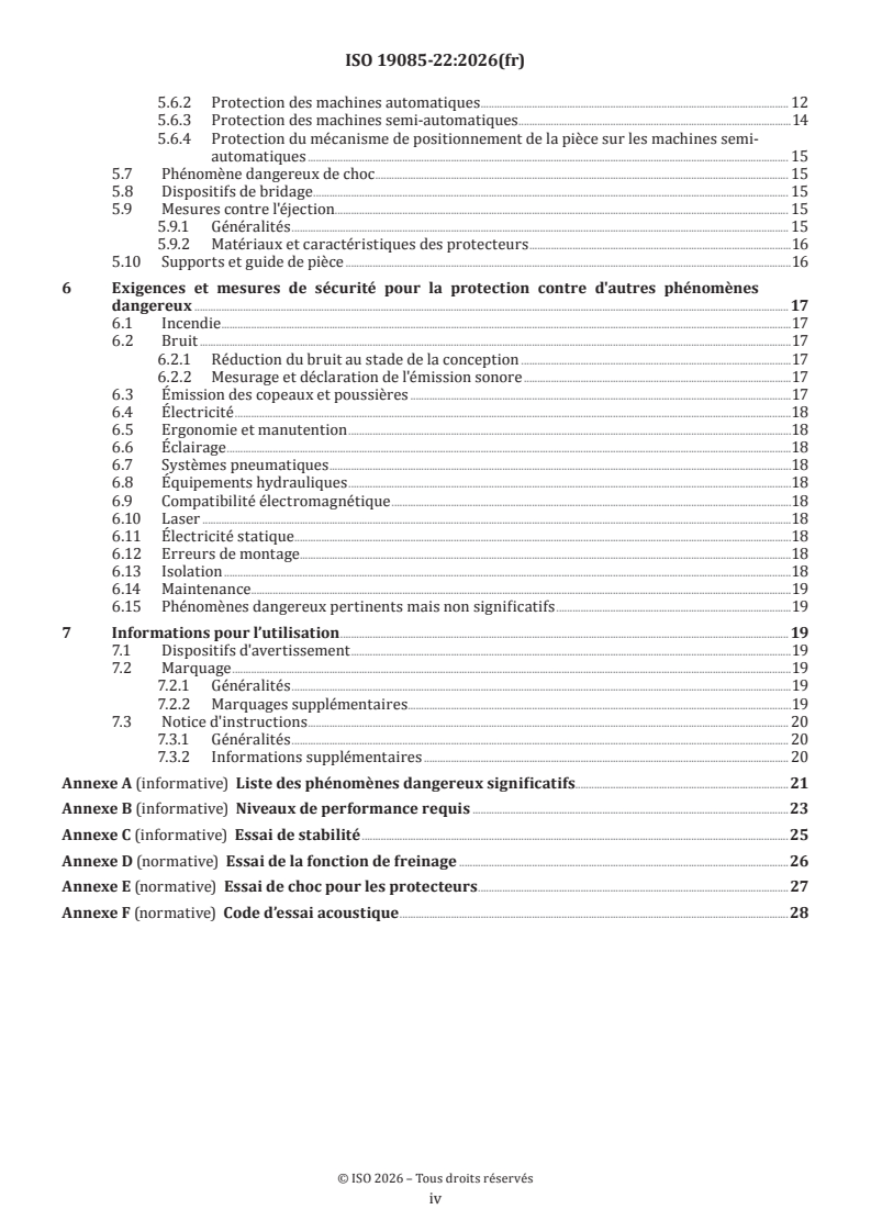
Sommaire Page
Avant-propos .v
Introduction .vi
1 Domaine d'application . 1
2 Références normatives . 1
3 Termes et définitions . 2
4 Exigences et mesures de sécurité pour les commandes . 3
4.1 Sécurité et fiabilité des systèmes de commande .3
4.2 Dispositifs de commande .4
4.3 Démarrage .6
4.3.1 Démarrage direct .6
4.3.2 Démarrage par commande de mise sous tension .6
4.3.3 Course de coupe .6
4.4 Arrêts sûrs .6
4.4.1 Généralités .6
4.4.2 Arrêt normal .6
4.4.3 Arrêt de fonctionnement .7
4.4.4 Arrêt d’urgence .7
4.5 Fonction de freinage des outils .7
4.6 Sélection du mode .7
4.7 Changement de vitesse d’outil .7
4.7.1 Changement de vitesse par déplacement des courroies sur les poulies .7
4.7.2 Changement de vitesse par moteur à changement incrémental de vitesse .7
4.7.3 Vitesse variable en continu par convertisseur de fréquence .7
4.8 Défaillance de toute alimentation en énergie .8
4.9 Commande de réarmement manuel.8
4.10 Détection et surveillance de l’arrêt .8
4.11 Surveillance de la vitesse des parties mobiles de la machine .8
4.12 Temporisation .8
4.13 Téléservice .8
4.14 Pivotement et inclinaison motorisés .8
5 Exigences et mesures de sécurité pour la protection contre les phénomènes dangereux
mécaniques . 9
5.1 Stabilité .9
5.2 Risque de rupture pendant le fonctionnement .9
5.3 Conception de l'outil et de la fixation de l’outil .9
5.3.1 Généralités .9
5.3.2 Blocage de l’arbre .9
5.3.3 Dispositif de fixation de la lame de scie circulaire .9
5.3.4 Dimension du flasque pour les lames de scie circulaires .10
5.4 Freinage .10
5.4.1 Freinage des outils .10
5.4.2 Temps d'arrêt maximal .10
5.4.3 Relâchement du frein .10
5.5 Moyens de protection .10
5.5.1 Protecteurs fixes .10
5.5.2 Protecteurs mobiles avec dispositif de verrouillage .10
5.5.3 Commande à action maintenue .10
5.5.4 Commande bimanuelle .10
5.5.5 Équipement de protection électro-sensible (ESPE) .11
5.5.6 Équipement de protection sensible à la pression (PSPE).11
5.5.7 Commande de validation .11
5.6 Prévention de l’accès aux parties mobiles dangereuses .11
5.6.1 Protection de la lame de scie dans sa position de repos .11
iii
5.6.2 Protection des machines automatiques . 12
5.6.3 Protection des machines semi-automatiques .14
5.6.4 Protection du mécanisme de positionnement de la pièce sur les machines semi-
automatiques . 15
5.7 Phénomène dangereux de choc . 15
5.8 Dispositifs de bridage . 15
5.9 Mesures contre l'éjection. 15
5.9.1 Généralités . 15
5.9.2 Matériaux et caractéristiques des protecteurs .16
5.10 Supports et guide de pièce .16
6 Exigences et mesures de sécurité pour la protection contre d'autres phénomènes
dangereux . 17
6.1 Incendie .17
6.2 Bruit .17
6.2.1 Réduction du bruit au stade de la conception .17
6.2.2 Mesurage et déclaration de l'émission sonore .17
6.3 Émission des copeaux et poussières .17
6.4 Électricité .18
6.5 Ergonomie et manutention .18
6.6 Éclairage .18
6.7 Systèmes pneumatiques .18
6.8 Équipements hydrauliques .18
6.9 Compatibilité électromagnétique .18
6.10 Laser .18
6.11 Électricité statique . .18
6.12 Erreurs de montage.18
6.13 Isolation .18
6.14 Maintenance .19
6.15 Phénomènes dangereux pertinents mais non significatifs .19
7 Informations pour l’utilisation . 19
7.1 Dispositifs d'avertissement .19
7.2 Marquage .19
7.2.1 Généralités .19
7.2.2 Marquages supplémentaires . . .19
7.3 Notice d'instructions . . 20
7.3.1 Généralités . 20
7.3.2 Informations supplémentaires . 20
Annexe A (informative) Liste des phénomènes dangereux significatifs.21
Annexe B (informative) Niveaux de performance requis .23
Annexe C (informative) Essai de stabilité .25
Annexe D (normative) Essai de la fonction de freinage .26
Annexe E (normative) Essai de choc pour les protecteurs .27
Annexe F (normative) Code d’essai acoustique .28
iv
Avant-propos
L'ISO (Organisation internationale de normalisation) est une fédération mondiale d'organismes nationaux
de normalisation (comités membres de l'ISO). L'élaboration des Normes internationales est en général
confiée aux comités techniques de l'ISO. Chaque comité membre intéressé par une étude a le droit de faire
partie du comité technique créé à cet effet. Les organisations internationales, gouvernementales et non
gouvernementales, en liaison avec l'ISO participent également aux travaux. L'ISO collabore étroitement avec
la Commission électrotechnique internationale (IEC) en ce qui concerne la normalisation électrotechnique.
Les procédures utilisées pour élaborer le présent document et celles destinées à sa mise à jour sont
décrites dans les Directives ISO/IEC, Partie 1. Il convient, en particulier, de prendre note des différents
critères d'approbation requis pour les différents types de documents ISO. Le présent document a
été rédigé conformément aux règles de rédaction données dans les Directives ISO/IEC, Partie 2 (voir
www.iso.org/directives).
L’ISO attire l’attention sur le fait que la mise en application du présent document peut entraîner l’utilisation
d’un ou de plusieurs brevets. L’ISO ne prend pas position quant à la preuve, à la validité et à l’applicabilité de
tout droit de brevet revendiqué à cet égard. À la date de publication du présent document, l’ISO n'avait pas
reçu notification qu’un ou plusieurs brevets pouvaient être nécessaires à sa mise en application. Toutefois,
il y a lieu d’avertir les responsables de la mise en application du présent document que des informations
plus récentes sont susceptibles de figurer dans la base de données de brevets, disponible à l'adresse
www.iso.org/brevets. L’ISO ne saurait être tenue pour responsable de ne pas avoir identifié tout ou partie de
tels droits de propriété.
Les appellations commerciales éventuellement mentionnées dans le présent document sont données pour
information, par souci de commodité, à l’intention des utilisateurs et ne sauraient constituer un engagement.
Pour une explication de la nature volontaire des normes, la signification des termes et expressions
spécifiques de l'ISO liés à l'évaluation de la conformité, ou pour toute information au sujet de l'adhésion de
l'ISO aux principes de l’Organisation mondiale du commerce (OMC) concernant les obstacles techniques au
commerce (OTC), voir www.iso.org/avant-propos.
Le présent document a été élaboré par le comité technique ISO/TC 39, Machines-outils, Sous-comité SC 4,
Machines à bois, en collaboration avec le comité technique CEN/TC 142, Machines à bois - Sécurité, du Comité
européen de normalisation (CEN) conformément à l'Accord de coopération technique entre l'ISO et le CEN
(Accord de Vienne).
Le présent document est destiné à être utilisé conjointement avec l'ISO 19085-1:2021.
Une liste de toutes les parties de la série ISO 19085 se trouve sur le site web de l’ISO.
Il convient que l’utilisateur adresse tout retour d’information ou toute question concernant le présent
document à l’organisme national de normalisation de son pays. Une liste exhaustive desdits organismes se
trouve à l’adresse www.iso.org/fr/members.html.
v
Introduction
La série ISO 19085 fournit les exigences techniques de sécurité pour la conception et la fabrication
des machines à bois ainsi que pour le contenu de la notice d'instructions correspondante. La série
ISO 19085 s'adresse aux concepteurs, fabricants, fournisseurs et importateurs des machines spécifiées dans
le Domaine d’application.
Le présent document est une norme de type C tel que mentionné dans l’ISO 12100:2010.
Le présent document concerne, en particulier, les groupes de parties prenantes suivants représentant les
acteurs du marché dans le domaine de la sécurité des machines:
— fabricants de machines (petites, moyennes et grandes entreprises);
— organismes de santé et de sécurité (autorités réglementaires, organismes de prévention des risques
professionnels, surveillance du marché, etc.).
D’autres partenaires peuvent être concernés par le niveau de sécurité des machines atteint au moyen du
document par les groupes de parties prenantes mentionnés ci-dessus.
— utilisateurs de machines/employeurs (petites, moyennes et grandes entreprises);
— utilisateurs de machines/salariés (par exemple syndicats de salariés, organisations représentant des
personnes ayant des besoins particuliers);
— prestataires de services, par exemple sociétés de maintenance (petites, moyennes et grandes entreprises);
— consommateurs (dans le cas de machines destinées à être utilisées par des consommateurs).
Les groupes de parties prenantes mentionnés ci-dessus ont eu la possibilité de participer à l’élaboration du
présent document.
Les machines concernées et l’étendue des phénomènes dangereux, situations dangereuses ou événements
dangereux couverts sont indiquées dans le domaine d’application du présent document.
Lorsque des exigences de la présente norme de type C sont différentes de celles énoncées dans les normes de
type A ou les normes de type B, les exigences de la présente norme de type C prévalent sur celles des autres
normes pour les machines ayant été conçues et fabriquées conformément aux exigences de la présente
norme de type C.
D'autres partenaires peuvent être affectés par le niveau de sécurité des machines obtenu au moyen du
document par les groupes de parties prenantes mentionnées ci-dessus:
— utilisateurs de machines/employeurs (petites, moyennes et grandes entreprises);
— utilisateurs de machines/employés (par exemple syndicats, organisations pour les personnes ayant des
besoins spéciaux);
— prestataires de services, par exemple sociétés de maintenance (petites, moyennes et grandes entreprises);
— consommateurs (dans le cas de machines destinées à être utilisées par des consommateurs).
Les groupes de parties prenantes mentionnés ci-dessus ont eu la possibilité de participer au processus
d’élaboration du présent document.
Les machines concernées et l'étendue des phénomènes dangereux, des situations dangereuses ou des
événements dangereux couverts, sont indiquées dans le Domaine d'application du présent document.
Lorsque des exigences de la présente norme de type C sont différentes de celles énoncées dans les normes
de type A ou de type B, les exigences de la présente norme de type C ont priorité sur les exigences des autres
normes pour les machines ayant été conçues et fabriquées selon les exigences de la présente norme de type C.
vi
L’ensemble des exigences pour un type particulier de machine à bois sont celles données dans la partie de
la série ISO 19085 applicable à ce type, conjointement avec les exigences pertinentes de l’ISO 19085-1:2021,
dans l’étendue spécifiée dans le Domaine d’application de la partie applicable de la série ISO 19085.
Dans la mesure du possible, les exigences de sécurité des parties de la série ISO 19085 font référence aux
articles correspondants de l’ISO 19085-1:2021. Chaque partie comprend des remplacements et des ajouts
aux exigences communes données dans l’ISO 19085-1:2021.
Toutes les parties de la série ISO 19085 ont la même structure, de sorte que la référence à l'ISO 19085-1:2021
se fait toujours et uniquement à partir de et vers le même numéro de paragraphe au dernier niveau de tiret.
Les Articles 1 à 3 sont spécifiques à chaque partie et, par conséquent, sont distincts de l'ISO 19085-1:2021,
Articles 1 à 3.
Pour les Articles 4 à 7 et les annexes, chaque paragraphe de l’ISO 19085-1:2021 est cité comme:
— confirmé dans son intégralité;
— confirmé avec des ajouts;
— exclu en totalité; ou
— remplacé par un texte spécifique.
Cela est indiqué par l’un des énoncés possibles suivants:
— «L’ISO 19085-1:2021, [paragraphe/Annexe] s’applique»;
— L’«ISO 19085-1:2021, [paragraphe/Annexe] s’applique avec les ajouts suivants» ou «l’ISO 19085-1:2021,
[paragraphe/Annexe] s'applique avec les ajouts suivants, divisée en de nouveaux paragraphes
spécifiques»;
— L’«ISO 19085-1:2021, [paragraphe/Annexe] ne s’applique pas»;
— L’«ISO 19085-1:2021, [paragraphe/Annexe] est remplacée par le texte suivant» ou
l’«ISO 19085-1:2021, [paragraphe/Annexe] est remplacée par le texte suivant, divisée en de nouveaux
paragraphes spécifiques».
Les autres paragraphes et annexes spécifiques au présent document sont indiqués par la phrase introductive:
«Paragraphe/Annexe spécifique au présent document.».
vii
Norme internationale ISO 19085-22:2026(fr)
Machines à bois — Sécurité —
Partie 22:
Tronçonneuses monolames automatiques et semi-
automatiques à coupe ascendante
1 Domaine d'application
Le présent document spécifie les exigences et les mesures de sécurité pour les tronçonneuses monolames
automatiques et semi-automatiques à coupe ascendante capables d’une utilisation en production continue et
ci-après également désignées «machines».
Les machines sont conçues pour la coupe de bois massif, de matériau ayant des caractéristiques physiques
similaires à celles du bois, et:
— les profilés en aluminium également remplis ou composés de matériaux isolants à base de plastique, de
mousse ou de caoutchouc;
— les matériaux en composite dont la base est constituée, par exemple, de polyuréthane ou d'un matériau
minéral stratifié en alliage léger;
— les matériaux en composite à matrice polymère et renforcés avec des matériaux thermoplastiques ou
thermodurcissables ou élastomères;
— la fibre de verre;
— les barres composites fabriquées à partir des matériaux énumérés ci-dessus.
Le présent document traite tous les phénomènes dangereux, situations dangereuses ou événements
dangereux significatifs, énumérés à l’Annexe A, qui sont pertinents pour les machines, lorsqu'elles sont
utilisées normalement et lorsqu’elles font l’objet d’un mauvais usage raisonnablement prévisible par le
fabricant.
Le présent document est également applicable aux autres phases du cycle de vie des machines: le transport,
l'assemblage, la maintenance, le démantèlement et la mise au rebut.
Tout équipement fixé sur la machine permettant le positionnement de la pièce est inclus dans le présent
document.
Le présent document ne traite pas des phénomènes dangereux spécifiques liés à la combinaison de machines
simples avec toute autre machine comme une partie d’une ligne.
Le présent document ne s’applique pas aux:
— machines conçues pour le tronçonnage de grumes;
— machines prévues pour une utilisation en atmosphère explosible;
— machines fabriquées avant la date de publication du présent document.
2 Références normatives
Les documents suivants sont cités dans le texte de sorte qu’ils constituent, pour tout ou partie de leur
contenu, des exigences du présent document. Pour les références datées, seule l’édition citée s’applique. Pour
les références non datées, la dernière édition du document de référence s'applique (y compris les éventuels
amendements).
ISO 12100:2010, Sécurité des machines — Principes généraux de conception — Appréciation du risque et
réduction du risque
ISO 13857:2019, Sécurité des machines — Distances de sécurité empêchant les membres supérieurs et inférieurs
d'atteindre les zones dangereuses
ISO 19085-1:2021, Machines à bois — Sécurité — Partie 1: Exigences communes
IEC 60204-1:2016, Sécurité des machines — Équipement électrique des machines — Partie 1: Exigences
générales
IEC 61800-5:2016, Entraînements électriques de puissance à vitesse variable — Partie 5-2: Exigences de
sécurité — Fonctionnelle
3 Termes et définitions
Pour les besoins du présent document, les termes et les définitions de l'ISO 12100:2010,
l’ISO 19085-1:2021 ainsi que les suivants s’appliquent.
L’ISO et l’IEC tiennent à jour des bases de données terminologiques destinées à être utilisées en normalisation,
consultables aux adresses suivantes:
— ISO Online browsing platform: disponible à l’adresse https:// www .iso .org/ obp
— IEC Electropedia: disponible à l’adresse https:// www .electropedia .org/
3.1
tronçonneuse à coupe ascendante
machine équipée d'une unité à avance mécanique pour une seule lame de scie, qui est entièrement située
sous le support de pièce lorsqu'elle est en position de repos (3.4)
Note 1 à l'article: Pour le tronçonnage, l'unité de sciage se déplace vers le haut de manière linéaire (voir Figure 1) ou le
long d’une trajectoire non linéaire.
Note 2 à l'article: L'unité de sciage peut être pivotée ou inclinée, ou les deux, par voie manuelle ou motorisée.
Légende
1 avant de la machine
2 unité de sciage en position de repos sous le support de pièce
3 rotation de la lame de scie
4 mouvement linéaire ascendant de l'unité de sciage
Figure 1 — Exemple d'une tronçonneuse à coupe ascendante (simplifié)
3.2
tronçonneuse semi-automatique
tronçonneuse à coupe ascendante (3.1) pour laquelle la pièce est positionnée manuellement ou au moyen d'un
mécanisme de positionnement motorisé à commande manuelle et la course de coupe (3.5) est déclenchée
manuellement pour chaque tronçonnage à la longueur souhaitée
3.3
tronçonneuse automatique
tronçonneuse à coupe ascendante (3.1) pour laquelle la pièce est positionnée automatiquement et dont le
cycle de coupe (3.6) est déclenché automatiquement pour un tronçonnage selon des longueurs et angles
présélectionnés
Note 1 à l'article: Les pièces sont généralement amenées à la machine au moyen d'un tampon de matériau, qui peut
être chargé manuellement ou automatiquement. Le déchargement des pièces coupées se fait généralement de manière
automatique.
3.4
position de repos
position de l'unité de sciage où la lame de scie se trouve sous la table de support de la pièce
où commence et finit la course de coupe (3.5)
3.5
course de coupe
mouvement d'avance de l'unité de sciage comportant l'outil en vue d'effectuer la coupe, suivi du retour de
l'unité de sciage à sa position de repos (3.4)
3.6
cycle de coupe
séquence automatique de déplacement du mécanisme de positionnement de la
pièce (3.8), de pivotement (3.9), d’inclinaison (3.10), et de course de coupe (3.5)
Note 1 à l'article: Plusieurs cycles de coupe peuvent être répétés automatiquement en fonction de la présélection.
3.7
commande de déclenchement
commande qui, après actionnement, permet de fournir l'alimentation à des actionneurs spécifiques de la
machine, par exemple, par un automate programmable
3.8
mécanisme de positionnement de la pièce
mécanisme permettant de pousser la pièce dans la position prévue en vue du tronçonnage à la longueur
souhaitée
3.9
pivotement
rotation de l’unité de sciage autour d’un axe vertical
3.10
inclinaison
rotation de l’unité de sciage autour d’un axe horizontal
4 Exigences et mesures de sécurité pour les commandes
4.1 Sécurité et fiabilité des systèmes de commande
L’ISO 19085-1:2021, 4.1 s'applique avec les ajouts suivants.
Le Tableau B.1 récapitule les niveaux de performance requis (PL ) spécifiés dans les Articles 4 et 5 pour
r
chaque fonction de sécurité.
4.2 Dispositifs de commande
L’ISO 19085-1:2021, 4.2 s'applique avec les ajouts suivants.
Les dispositifs de commande pour le démarrage de l'entraînement de l'arbre de la lame de scie, l'arrêt normal,
la sélection du mode de fonctionnement (lorsque montée) et l'avance motorisée de la pièce (lorsque montée)
doivent être situés ensemble sur la machine ou sur un panneau de commande séparé (fixe ou mobile) à partir
duquel il est possible de voir la machine.
Lorsque les dispositifs de commande sont situés sur un panneau de commande mobile, les exigences
suivantes doivent être satisfaites:
— il doit être raccordé à la machine par un câble;
— sa position doit être indiquée dans la notice d'instructions.
Le sélecteur de mode et le dispositif de commande de réarmement ne doivent pas être situés sur un panneau
de commande mobile.
Lorsqu'un dispositif de commande est dupliqué sur deux panneaux de commande différents, seul un
ensemble de dispositifs de commande dupliqués doit être actif à la fois, à l'exception des arrêts de sécurité.
Les parties du système de commande relatives à la sécurité (SRP/CS) pour la sélection de l’ensemble actif de
dispositifs de commande doivent atteindre PL = c.
r
Lorsque la machine est équipée d'un dispositif de commande bimanuelle, celui-ci doit être positionné:
— sur la face avant de la machine, centré par rapport à la ligne de coupe (voir Figure 2 et Figure 3);
— sous le support de pièce;
— à une hauteur minimale de 750 mm au-dessus du niveau du sol.
Dimensions en millimètres
Légende
1 ligne de coupe
2 actionneurs de commande manuelle du dispositif de commande bimanuelle
3 protecteur supérieur de la lame de scie servant également de dispositif de bridage
4 dispositif d’empêchement sur le devant
Figure 2 — Position du dispositif de commande bimanuelle et du dispositif d’empêchement sur les
machines avec protecteur supérieur servant de dispositif de bridage
Lorsque la commande pour le bridage motorisé de la pièce est séparée du dispositif de commande bimanuelle,
elle doit être au maximum à 400 mm mesuré à l'horizontale du dispositif de commande bimanuelle.
Les dispositifs d'arrêt d'urgence requis au 4.4.4 doivent être positionnés:
a) sur la zone de chargement, tous les 2 m;
b) sur la zone de déchargement, tous les 2 m;
c) sur le panneau de commande principal;
d) à 500 mm maximum du dispositif de commande bimanuelle (lorsqu'il est fourni);
e) à 3,0 m maximum de l'unité de sciage;
f) sur un panneau de commande séparé, le cas échéant.
Si la distance entre deux ou plusieurs des positions ci-dessus est inférieure à 1 m, un seul dispositif de
commande d'arrêt d'urgence est requis au lieu de deux.
Dimensions en millimètres
Légende
1 ligne de coupe
2 dispositif de commande bimanuelle
3 dispositif d’empêchement avant et supérieur
Figure 3 — Position du dispositif de commande bimanuelle et du dispositif d’empêchement avant et
supérieur
4.3 Démarrage
4.3.1 Démarrage direct
L’ISO 19085-1:2021, 4.3.1 s'applique.
4.3.2 Démarrage par commande de mise sous tension
L’ISO 19085-1:2021, 4.3.2 s'applique avec les ajouts suivants.
Le mécanisme de positionnement motorisé de la pièce, si la machine en est équipée, ne doit fonctionner que
vers la ligne de coupe lorsque la lame de scie se trouve en dessous de la table de support.
Les SRP/CS pour le verrouillage du mécanisme de positionnement de la pièce lorsqu’il se déplace vers la
ligne de coupe avec la position de repos de l’unité de sciage doivent atteindre PL = c.
r
En alternative, sur les machines automatiques, les SRP/CS pour le verrouillage du mécanisme de
positionnement de la pièce lorsqu’il se déplace vers la ligne de coupe, avec l’unité de sciage en position de
repos, peuvent atteindre PL = b, mais dans ce cas, les protecteurs mobiles avec dispositif de verrouillage
r
requis en 5.6.2 et le dispositif d’empêchement requis en 5.6.3 b) doivent être constitués de protecteurs de
classe A (voir 5.9.2.2).
4.3.3 Course de coupe
Paragraphe spécifique au présent document.
La course de coupe ne doit pouvoir être démarrée que lorsque la rotation de la lame de scie et le bridage
motorisé de la pièce, si la machine en est équipée, ont été déclenchés.
Cela peut être assuré par un verrouillage ou par conception, par exemple, un actionneur qui active d’abord le
bridage, puis la course de coupe ascendante (aucun PL n’est requis dans ce cas).
Les SRP/CS pour le verrouillage de la course de coupe avec le déclenchement de la rotation de la lame de scie
doivent atteindre PL = c.
r
Les SRP/CS pour le verrouillage de la course de coupe avec le déclenchement du bridage motorisé de la pièce
doivent atteindre PL = c.
r
Sur les machines semi-automatiques, chaque course de coupe doit être démarrée à l'aide d'un dispositif de
commande manuel.
4.4 Arrêts sûrs
4.4.1 Généralités
L’ISO 19085-1:2021, 4.4.1 s'applique avec les ajouts suivants.
La séquence d'arrêt doit se dérouler comme suit:
a) déclenchement de la course de retour de la lame de scie;
b) arrêt de l'entraînement de l'outil jusqu'à un arrêt de catégorie 0 ou 1.
À la fin de la séquence d'arrêt, le dispositif de bridage motorisé de la pièce doit être maintenu si le relâchement
du bridage risque de causer un phénomène dangereux quelconque, (par exemple, en raison de la pesanteur).
4.4.2 Arrêt normal
L’ISO 19085-1:2021, 4.4.2 s'applique.
4.4.3 Arrêt de fonctionnement
L’ISO 19085-1:2021, 4.4.3 s'applique.
4.4.4 Arrêt d’urgence
L’ISO 19085-1:2021, 4.4.4 s'applique.
4.5 Fonction de freinage des outils
L’ISO 19085-1:2021, 4.5 s'applique.
4.6 Sélection du mode
L’ISO 19085-1:2021, 4.6, est remplacé par le texte suivant.
Un sélecteur de mode doit être fourni sur les machines conçues pour fonctionner à la fois en tant que machine
semi-automatique et en tant que machine automatique. Ces machines doivent satisfaire à toutes les exigences
énoncées en 5.6.2 pour les machines automatiques, lorsqu’elles fonctionnent en mode automatique, et à
toutes les exigences énoncées en 5.6.3 pour les machines semi-automatiques, lorsqu’elles fonctionnent en
mode semi-automatique.
L’IEC 60204-1:2016, 9.2.3.5 s'applique.
La sélection du mode de fonctionnement doit être conforme aux exigences suivantes (voir également
ISO 12100:2010, 6.2.11.10):
a) le mode de fonctionnement sélectionné doit avoir la priorité sur tous les autres modes de commande ou
de fonctionnement, excepté l'arrêt d'urgence;
b) le sélecteur de mode de fonctionnement doit être blocable dans toutes les positions (par exemple, par un
interrupteur à clé);
c) un changement de mode de fonctionnement ne doit déclencher aucun mouvement de la machine;
d) lors de changement de modes, la machine doit être amenée à un arrêt sûr.
Les SRP/CS pour la sélection du mode de fonctionnement doivent atteindre PL = c.
r
4.7 Changement de vitesse d’outil
4.7.1 Changement de vitesse par déplacement des courroies sur les poulies
L’ISO 19085-1:2021, 4.7.1 s'applique.
4.7.2 Changement de vitesse par moteur à changement incrémental de vitesse
L’ISO 19085-1:2021, 4.7.2 s'applique.
4.7.3 Vitesse variable en continu par convertisseur de fréquence
L’ISO 19085-1:2021, 4.7.3, est remplacé par le texte suivant.
Les entraînements d’outils équipés d'une commande de vitesse variable en continu (également connue sous
le nom de convertisseur de fréquence) doivent comporter une surveillance de la vitesse.
La commande de surveillance de la vitesse doit assurer que, dès que la vitesse dépasse sa valeur limite
de plus de 10 %, l'entraînement est arrêté automatiquement en arrêt de catégorie 0 conformément à
l’IEC 60204-1:2016, 9.2.2.
NOTE 1 Un écart de la vitesse par rapport à la valeur prévue peut être causé, par exemple, par une erreur dans
la transmission de la valeur sélectionnée entre l’IHM et le convertisseur, ou par une erreur dans le générateur
d'impulsions rotatif de la commande de vitesse variable en continu.
La valeur de vitesse limite doit être préréglée par le fabricant de la machine pour chaque entraînement.
Les SRP/CS pour la surveillance de la vitesse doivent atteindre PL = c.
r
Pour la surveillance de la vitesse du PDS(SR) (système d’entraînement de puissance relatif à la sécurité),
l’IEC 61800-5-2:2016, 4.2.4.5 [limitation sûre de la vitesse (SLS)] doit s’appliquer.
NOTE 2 La valeur de vitesse de l’outil sélectionnée par l’opérateur ou par le système de commande peut être
inférieure à la valeur de vitesse limite préréglée par le fabricant de la machine pour l’entraînement concerné.
4.8 Défaillance de toute alimentation en énergie
L’ISO 19085-1:2021, 4.8 s'applique avec les ajouts suivants.
En cas de perte de puissance pneumatique lors du changement de lame de scie, la lame de scie doit rester
dans sa position de changement.
4.9 Commande de réarmement manuel
L’ISO 19085-1:2021, 4.9 s'applique.
4.10 Détection et surveillance de l’arrêt
L’ISO 19085-1:2021, 4.10 s'appliq
...