

ISO 21075:2026
(Main)Design and assessment process of whole-building mechanical ventilation systems in residential buildings
- Abstract
This document describes steps for designing and assessing the whole-building mechanical ventilation system for residential buildings, and the points to be taken into account regarding indoor environment and energy consumption. This document allows the designer to plan a whole-building mechanical ventilation system that improves indoor air quality, the auditory environment and thermal comfort, while also using energy in a practical way. It describes the performance of the building in order to effectively operate a whole-building mechanical ventilation system. This document does not cover: criteria for indoor air quality; criteria for indoor thermal comfort (covered by ISO/TC 159); criteria for auditory environment (covered by ISO/TC 43); evaluation methods of energy performance of heating and cooling equipment; evaluation methods of energy performance of ventilators (covered by ISO/TC 86); evaluation methods of energy performance of heat recovery components (covered by ISO/TC 86); evaluation methods of building performance (covered by ISO/TC 163); design steps and evaluation method of localized ventilation equipment; ventilation systems using natural driving force in all ventilation airflow paths.
- Status
- Published
- Publication Date
- 17-Nov-2026
- Technical Committee
- ISO/TC 205 - Building environment design
- Drafting Committee
- ISO/TC 205 - Building environment design
- Current Stage
- 6060 - International Standard published
- Start Date
- 18-Nov-2026
- Completion Date
- 18-Nov-2026
ISO 21075:2026 is an International Standard from ISO on the design and assessment process for whole-building mechanical ventilation systems in residential buildings. It sets out a staged method for planning, checking and finalizing a system so that indoor air quality, thermal comfort, acoustics and energy use are considered together.
What does ISO 21075:2026 specify?
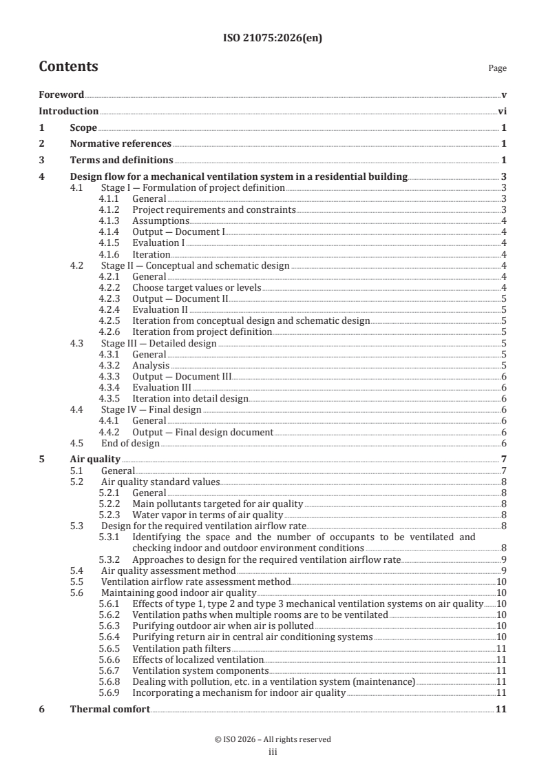
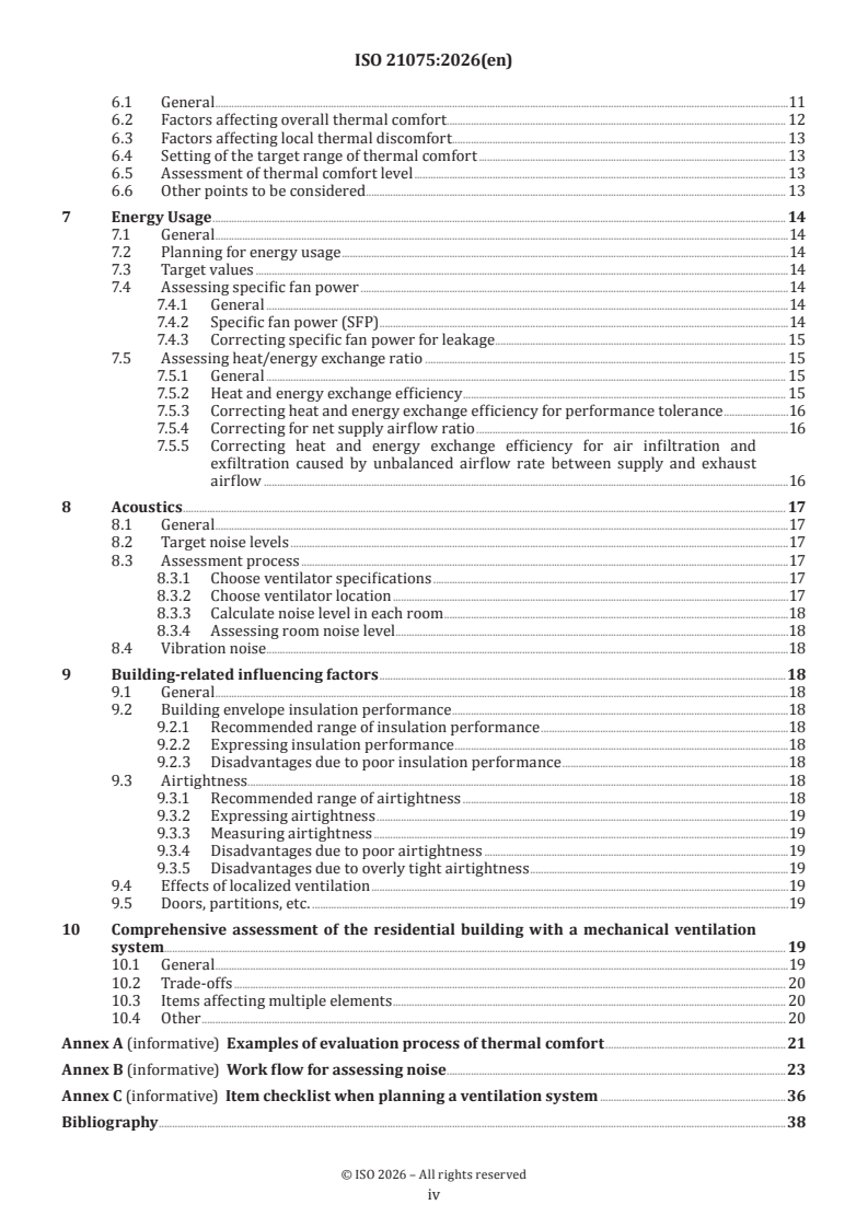
ISO 21075:2026 specifies a workflow for designing and assessing a whole-building mechanical ventilation system for a residential building. The document is organized as a design process in Clauses 4 to 10, with supporting examples and a planning checklist in Annexes A to C.
The standard focuses on whole-building mechanical ventilation and on the building conditions that affect it. It also points readers to related criteria and methods handled elsewhere, including indoor air quality criteria, thermal comfort criteria, auditory environment criteria, energy performance of heating and cooling equipment, ventilators, heat recovery components and buildings, localized ventilation, and systems driven entirely by natural forces.
| Annex | What it covers |
|---|---|
| Annex A | Examples of the evaluation process of thermal comfort |
| Annex B | Workflow for assessing noise |
| Annex C | Item checklist when planning a ventilation system |
Clauses 4 to 10 cover the design flow, air quality, thermal comfort, energy use, acoustics, building-related influencing factors and comprehensive assessment. In practice, this means the document is meant to be used from early project definition through final design handover.
What are the key requirements of ISO 21075:2026?
ISO 21075:2026 is built around a four-stage design flow and then a series of checks for air quality, comfort, energy and acoustics. The document is practical: it tells the designer what to define early, what to analyze later, and what to verify before the design is accepted.
Stage-based design and approval
Clause 4 splits the work into project definition, conceptual and schematic design, detailed design, and final design. Each stage produces a document - Document I, Document II, Document III and a final design document - and each one must be approved before the process moves on.
This matters because the standard requires the team to capture requirements, constraints and assumptions early, then confirm targets, then confirm predicted performance. If a design does not pass approval, the clause requires iteration back to the earlier stage that can still solve the issue.
Air quality target setting and airflow design
Clause 5 requires the designer to identify the space to be ventilated, the number of occupants and the indoor and outdoor conditions before choosing a ventilation airflow rate. The clause gives several design approaches: based on occupants, on room volume, on both together, on pollutant concentration, or on infection-risk reduction during epidemic periods.
This matters in practice because the ventilation rate is not treated as a single fixed number. The standard links the chosen airflow to the pollution source, the occupied space and the intended health or comfort outcome.
Air quality assessment and maintenance
Clause 5 also requires assessment of indoor air quality after construction or at occupancy by measuring airborne pollutant concentrations against baseline values from relevant guidance. It also requires checking that the built system can deliver the required airflow, including loss of pressure and the net supply airflow ratio (NSAR).
The clause further explains how system type affects air quality. A type 1 mechanical ventilation system, with mechanical supply and exhaust, is preferred for balanced airflow, while type 2 and type 3 systems can create moisture or pollutant risks in some conditions. The clause also emphasizes filters, pollutant purification, maintenance access and regular cleaning or replacement.
Thermal comfort assessment
Clause 6 treats thermal comfort through both whole-body and local discomfort factors. It uses predicted mean vote (PMV) and predicted percentage dissatisfied (PPD) for overall comfort, and it considers draught, vertical air temperature difference, floor surface temperature and radiant asymmetry for local discomfort.
This matters because the standard does not treat a room as comfortable just because average temperature looks acceptable. It asks the designer to consider the room type, occupancy pattern and local effects, and then to assess comfort by measurement or calculation.
Energy use and heat recovery checks
Clause 7 focuses on specific fan power (SFP) and heat/energy exchange performance. It requires planning to reduce pressure loss, using short and large ducts where possible, and checking SFP against the document’s target value. It also requires corrected checks for leakage, net supply airflow ratio and balance between supply and exhaust airflows in heat/energy recovery systems.
This matters because a ventilation system can meet airflow targets while still using too much energy. The clause gives designers a way to compare fan power and recovery performance with the actual airflow delivered in the building.
Acoustics and vibration
Clause 8 requires target noise levels to be set, ventilator specifications to be chosen with noise in mind, ventilator location to be planned, and room noise to be calculated and compared with the target. It also requires ventilator vibration to be isolated from building structures.
This matters because fan selection, placement and duct layout affect whether a system is acceptable in occupied rooms. Annex B supports this with a workflow for selecting equipment and estimating noise.
Building factors and trade-offs
Clauses 9 and 10 require the designer to check insulation performance, airtightness, localized ventilation, interior doors and partitions, and then to assess trade-offs across all the factors. The document explicitly notes that better air quality can increase heating or cooling load, fan load, maintenance needs and noise, while better insulation or airtightness can improve thermal comfort and make the mechanical system work as intended.
This matters because the standard is not a one-issue checklist. It is meant to help the designer balance competing goals and document the decisions made.
What terms does ISO 21075:2026 define?
ISO 21075:2026 defines the core system and performance terms used throughout the document. The definitions are important because the design checks depend on consistent meaning.
- Whole-building mechanical ventilation system - a system that provides integrated or simultaneous ventilation for two or more spaces in a building, including one or more habitable rooms.
- Airtightness - a quantitative index showing the amount of gap in the building envelope.
- Air change rate - the air supply divided by room air volume, expressed as air changes per hour.
- Supply airflow (SA) - air going from the ventilator to the rooms.
- Exhaust airflow (EA) - air going from the ventilator to outdoors.
- Designed airflow - the ventilation flow rate estimated from blower static pressure characteristics and the airflow path, including ducts.
- Specific fan power (SFP) - mechanical ventilating system power consumption divided by designed airflow.
- Net supply airflow ratio (NSAR) - the ratio of net supply airflow rate to supply airflow rate.
Who uses ISO 21075:2026?
ISO 21075:2026 is for people who design, assess, specify or review residential ventilation systems. That includes ventilation engineers, building services designers, HVAC consultants, architects working with building services teams, and reviewers who need to check that the design logic is complete.
It is also useful for quality managers, builders and commissioning teams because it shows what needs to be documented at each design stage and what should be checked before handover. Manufacturers and suppliers of ventilators, filters, ducts and recovery devices can also use it to understand how their products fit into the system-level design process.
Which standards are used with ISO 21075:2026?
ISO 21075:2026 refers to several standards that support its calculations, measurements and target setting.
- ISO 17772-1 - provides indoor environmental input parameters for design and assessment of building energy performance, and supports the document’s air quality and thermal comfort work.
- ISO 52000-1 - provides the overarching EPB assessment framework and procedures used for energy performance context.
- ISO 7730 - is cited for PMV, PPD and local thermal comfort criteria.
- ISO 16000-6 - supports measurement of volatile organic compounds.
- ISO 16000-3 - supports measurement of aldehydes.
- ISO 16890-1 and EN 779 - are used for ventilation filter specification and classification.
- EN 15780 - supports duct cleanliness and maintenance planning.
- ISO 9972 - is referenced for airtightness measurement by fan pressurization.
- ISO 16494 series - is pointed to for more detail on energy-saving and heat/energy recovery ventilation.
- WHO guidelines - are used for pollutant limits, dampness and COVID-19 related ventilation guidance.
What does the ISO 21075:2026 document contain?
ISO 21075:2026 contains a staged design flow, formula-based assessment methods and practical annexes for thermal comfort and noise. It uses formulas for steady-state pollutant concentration, specific fan power, corrected specific fan power, and corrected heat/energy exchange efficiency.
It also includes examples of thermal comfort evaluation in different room types, with PMV and PPD target-setting guidance in Annex A. Annex B provides a noise assessment workflow, including equipment selection, target noise setting and calculation steps for room and vent noise. Annex C gives a checklist that helps a design team document decisions on air quality, comfort, energy saving, acoustics and building-related factors.
The body of the document is organized so that each topic supports a design decision: choose targets, calculate or measure performance, check trade-offs, and then document the final system.
Get Certified
Connect with accredited certification bodies for this standard

DIBt (Deutsches Institut für Bautechnik)
German Institute for Building Technology.

DIN CERTCO
DIN Group product certification.

Aboma Certification B.V.
Specialized in construction, metal, and transport sectors.
Sponsored listings
Frequently Asked Questions
ISO 21075:2026 is a standard published by the International Organization for Standardization (ISO). Its full title is "Design and assessment process of whole-building mechanical ventilation systems in residential buildings". This standard covers: This document describes steps for designing and assessing the whole-building mechanical ventilation system for residential buildings, and the points to be taken into account regarding indoor environment and energy consumption. This document allows the designer to plan a whole-building mechanical ventilation system that improves indoor air quality, the auditory environment and thermal comfort, while also using energy in a practical way. It describes the performance of the building in order to effectively operate a whole-building mechanical ventilation system. This document does not cover: criteria for indoor air quality; criteria for indoor thermal comfort (covered by ISO/TC 159); criteria for auditory environment (covered by ISO/TC 43); evaluation methods of energy performance of heating and cooling equipment; evaluation methods of energy performance of ventilators (covered by ISO/TC 86); evaluation methods of energy performance of heat recovery components (covered by ISO/TC 86); evaluation methods of building performance (covered by ISO/TC 163); design steps and evaluation method of localized ventilation equipment; ventilation systems using natural driving force in all ventilation airflow paths.
This document describes steps for designing and assessing the whole-building mechanical ventilation system for residential buildings, and the points to be taken into account regarding indoor environment and energy consumption. This document allows the designer to plan a whole-building mechanical ventilation system that improves indoor air quality, the auditory environment and thermal comfort, while also using energy in a practical way. It describes the performance of the building in order to effectively operate a whole-building mechanical ventilation system. This document does not cover: criteria for indoor air quality; criteria for indoor thermal comfort (covered by ISO/TC 159); criteria for auditory environment (covered by ISO/TC 43); evaluation methods of energy performance of heating and cooling equipment; evaluation methods of energy performance of ventilators (covered by ISO/TC 86); evaluation methods of energy performance of heat recovery components (covered by ISO/TC 86); evaluation methods of building performance (covered by ISO/TC 163); design steps and evaluation method of localized ventilation equipment; ventilation systems using natural driving force in all ventilation airflow paths.
ISO 21075:2026 is classified under the following ICS (International Classification for Standards) categories: 91.140.30 - Ventilation and air-conditioning systems. The ICS classification helps identify the subject area and facilitates finding related standards.
ISO 21075:2026 is available in PDF format for immediate download after purchase. The document can be added to your cart and obtained through the secure checkout process. Digital delivery ensures instant access to the complete standard document.
Standards Content (Sample)
International
Standard
ISO 21075
First edition
Design and assessment process
2026-11
of whole-building mechanical
ventilation systems in residential
buildings
Processus de conception et d'évaluation des systèmes de
ventilation mécanique de l'ensemble du bâtiment dans les
bâtiments résidentiels
Reference number
© ISO 2026
All rights reserved.
This ISO publication is protected by copyright and is owned by ISO and/or its licensors.
The content of this ISO publication is provided under licence, not sold. Use is subject to the applicable licence terms issued by ISO,
an ISO member body, or an authorized third-party distributor.
Except as required for implementation or expressly permitted by a separate licence, no part of this ISO publication may be
reproduced, distributed, modified, used, or made available in any form or by any means – electronic or mechanical, including
photocopying, scanning, recording, or posting on internal or external digital platforms.
Any use beyond the scope of the granted rights is prohibited and may result in legal action.
ISO copyright office
CP 401 • CH-1214 Vernier, Geneva
Phone: +41 22 749 01 11
Email: copyright@iso.org
Website: www.iso.org
Published in Switzerland
ii
Contents Page
Foreword .v
Introduction .vi
1 Scope . 1
2 Normative references . 1
3 Terms and definitions . 1
4 Design flow for a mechanical ventilation system in a residential building . 3
4.1 Stage I ― Formulation of project definition .3
4.1.1 General .3
4.1.2 Project requirements and constraints .3
4.1.3 Assumptions .4
4.1.4 Output ― Document I.4
4.1.5 Evaluation I .4
4.1.6 Iteration .4
4.2 Stage II ― Conceptual and schematic design .4
4.2.1 General .4
4.2.2 Choose target values or levels .4
4.2.3 Output ― Document II . .5
4.2.4 Evaluation II .5
4.2.5 Iteration from conceptual design and schematic design .5
4.2.6 Iteration from project definition .5
4.3 Stage III ― Detailed design .5
4.3.1 General .5
4.3.2 Analysis .5
4.3.3 Output ― Document III . .6
4.3.4 Evaluation III .6
4.3.5 Iteration into detail design .6
4.4 Stage IV ― Final design .6
4.4.1 General .6
4.4.2 Output ― Final design document .6
4.5 End of design .6
5 Air quality . 7
5.1 General .7
5.2 Air quality standard values.8
5.2.1 General .8
5.2.2 Main pollutants targeted for air quality .8
5.2.3 Water vapor in terms of air quality .8
5.3 Design for the required ventilation airflow rate.8
5.3.1 Identifying the space and the number of occupants to be ventilated and
checking indoor and outdoor environment conditions .8
5.3.2 Approaches to design for the required ventilation airflow rate .9
5.4 Air quality assessment method .9
5.5 Ventilation airflow rate assessment method .10
5.6 Maintaining good indoor air quality .10
5.6.1 Effects of type 1, type 2 and type 3 mechanical ventilation systems on air quality .10
5.6.2 Ventilation paths when multiple rooms are to be ventilated .10
5.6.3 Purifying outdoor air when air is polluted .10
5.6.4 Purifying return air in central air conditioning systems .10
5.6.5 Ventilation path filters .11
5.6.6 Effects of localized ventilation .11
5.6.7 Ventilation system components .11
5.6.8 Dealing with pollution, etc. in a ventilation system (maintenance) .11
5.6.9 Incorporating a mechanism for indoor air quality .11
6 Thermal comfort .11
iii
6.1 General .11
6.2 Factors affecting overall thermal comfort. 12
6.3 Factors affecting local thermal discomfort. 13
6.4 Setting of the target range of thermal comfort . 13
6.5 Assessment of thermal comfort level . 13
6.6 Other points to be considered . . 13
7 Energy Usage . 14
7.1 General .14
7.2 Planning for energy usage .14
7.3 Target values .14
7.4 Assessing specific fan power .14
7.4.1 General .14
7.4.2 Specific fan power (SFP) .14
7.4.3 Correcting specific fan power for leakage . 15
7.5 Assessing heat/energy exchange ratio . 15
7.5.1 General . 15
7.5.2 Heat and energy exchange efficiency . 15
7.5.3 Correcting heat and energy exchange efficiency for performance tolerance .16
7.5.4 Correcting for net supply airflow ratio .16
7.5.5 Correcting heat and energy exchange efficiency for air infiltration and
exfiltration caused by unbalanced airflow rate between supply and exhaust
airflow .16
8 Acoustics . 17
8.1 General .17
8.2 Target noise levels .17
8.3 Assessment process .17
8.3.1 Choose ventilator specifications .17
8.3.2 Choose ventilator location .17
8.3.3 Calculate noise level in each room .18
8.3.4 Assessing room noise level .18
8.4 Vibration noise . .18
9 Building-related influencing factors .18
9.1 General .18
9.2 Building envelope insulation performance .18
9.2.1 Recommended range of insulation performance .18
9.2.2 Expressing insulation performance .18
9.2.3 Disadvantages due to poor insulation performance .18
9.3 Airtightness . .18
9.3.1 Recommended range of airtightness .18
9.3.2 Expressing airtightness .19
9.3.3 Measuring airtightness .19
9.3.4 Disadvantages due to poor airtightness .19
9.3.5 Disadvantages due to overly tight airtightness .19
9.4 Effects of localized ventilation .19
9.5 Doors, partitions, etc. .19
10 Comprehensive assessment of the residential building with a mechanical ventilation
system. 19
10.1 General .19
10.2 Trade-offs . 20
10.3 Items affecting multiple elements . 20
10.4 Other . 20
Annex A (informative) Examples of evaluation process of thermal comfort .21
Annex B (informative) Work flow for assessing noise .23
Annex C (informative) Item checklist when planning a ventilation system .36
Bibliography .38
iv
Foreword
ISO (the International Organization for Standardization) is a worldwide federation of national standards
bodies (ISO member bodies). The work of preparing International Standards is normally carried out through
ISO technical committees. Each member body interested in a subject for which a technical committee
has been established has the right to be represented on that committee. International organizations,
governmental and non-governmental, in liaison with ISO, also take part in the work. ISO collaborates closely
with the International Electrotechnical Commission (IEC) on all matters of electrotechnical standardization.
The procedures used to develop this document and those intended for its further maintenance are described
in the ISO/IEC Directives, Part 1. In particular, the different approval criteria needed for the different types
of ISO document should be noted. This document was drafted in accordance with the editorial rules of the
ISO/IEC Directives, Part 2 (see www.iso.org/directives).
ISO draws attention to the possibility that the implementation of this document may involve the use of (a)
patent(s). ISO takes no position concerning the evidence, validity or applicability of any claimed patent
rights in respect thereof. As of the date of publication of this document, ISO had not received notice of (a)
patent(s) which may be required to implement this document. However, implementers are cautioned that
this may not represent the latest information, which may be obtained from the patent database available at
www.iso.org/patents. ISO shall not be held responsible for identifying any or all such patent rights.
Any trade name used in this document is information given for the convenience of users and does not
constitute an endorsement.
For an explanation of the voluntary nature of standards, the meaning of ISO specific terms and expressions
related to conformity assessment, as well as information about ISO's adherence to the World Trade
Organization (WTO) principles in the Technical Barriers to Trade (TBT), see www.iso.org/iso/foreword.html.
This document was prepared by Technical Committee ISO/TC 205, Building environment design.
Any feedback or questions on this document should be directed to the user’s national standards body. A
complete listing of these bodies can be found at www.iso.org/members.html.
v
Introduction
Energy conservation in buildings is a pressing issue, while occupants increasingly demand comfortable
indoor environments. Though ventilation can maintain good indoor air quality and prevent infections, it
also brings cold/hot outdoor air indoors in the winter/summer season, which increases the heating/cooling
demand. Therefore, reconciling a good indoor environment and energy conservation in the process of
designing the whole-building ventilation system of a residential building is an important consideration.
Other national and international standards, and technical reports, exist that specify criteria for indoor air
quality, thermal comfort and the auditory environment. Other standards also specify methods for evaluating
the energy performance of ventilators, heat and energy recover components, heating and cooling equipment,
and buildings.
Designers can assess these factors using relevant standards when designing a ventilation system,
however, one or more factors risk being omitted because the designers consider and organize freely the
factors relevant to thermal comfort, indoor air quality, auditory environment and energy performance.
Furthermore, the ventilation system's performance can vary according to the design, even if the designer
chooses the same components.
This document specifies the steps for designing the whole-building ventilation system of a residential
building, and the points to be considered regarding indoor environment and energy consumption. This
document can help designers consider and organize factors in designing the whole-building ventilation
system, which can attain both a good indoor environment and energy conservation.
vi
International Standard ISO 21075:2026(en)
Design and assessment process of whole-building mechanical
ventilation systems in residential buildings
1 Scope
This document describes steps for designing and assessing the whole-building mechanical ventilation
system for residential buildings, and the points to be taken into account regarding indoor environment and
energy consumption. This document allows the designer to plan a whole-building mechanical ventilation
system that improves indoor air quality, the auditory environment and thermal comfort, while also using
energy in a practical way. It describes the performance of the building in order to effectively operate a
whole-building mechanical ventilation system.
This document does not cover:
— criteria for indoor air quality;
— criteria for indoor thermal comfort (covered by ISO/TC 159);
— criteria for auditory environment (covered by ISO/TC 43);
— evaluation methods of energy performance of heating and cooling equipment;
— evaluation methods of energy performance of ventilators (covered by ISO/TC 86);
— evaluation methods of energy performance of heat recovery components (covered by ISO/TC 86);
— evaluation methods of building performance (covered by ISO/TC 163);
— design steps and evaluation method of localized ventilation equipment;
— ventilation systems using natural driving force in all ventilation airflow paths.
2 Normative references
The following documents are referred to in the text in such a way that some or all of their content constitutes
requirements of this document. For dated references, only the edition cited applies. For undated references,
the latest edition of the referenced document (including any amendments) applies.
ISO 17772-1, Energy performance of buildings — Indoor environmental quality — Part 1: Indoor environmental
input parameters for the design and assessment of energy performance of buildings
ISO 52000-1, Energy performance of buildings — Overarching EPB assessment — Part 1: General framework
and procedures
3 Terms and definitions
For the purposes of this document, the terms and definitions given in ISO 17772-1, ISO 52000-1 and the
following apply.
ISO and IEC maintain terminology databases for use in standardization at the following addresses:
— ISO Online browsing platform: available at https:// www .iso .org/ obp
— IEC Electropedia: available at https:// www .electropedia .org/
3.1
whole-building mechanical ventilation system
system for providing integrated or simultaneous ventilation for two or more spaces in a building including
one or more habitable rooms
3.2
airtightness
quantitative index showing amount of gap in the building envelope
3.3
air change rate
value obtained by dividing air supply by room air volume, expressed as the number of air changes per hour
Note 1 to entry: Air change rate is expressed as the number of air changes per hour (1/h).
3.4
supply airflow
SA
air going from ventilator to rooms
3.5
supply airflow rate
amount of supply airflow
3.6
power consumption
total power consumed by a component
Note 1 to entry: Power consumption is expressed as watt (W).
3.7
designed airflow
flow rate for ventilation equipment estimated based on the characteristics of the blower static pressure flow
rate and the characteristics of the static pressure flow rate of the air conveyance path composed of ducts,
etc.
Note 1 to entry: Designed airflow is expressed as cube meter per hour (m /h).
3.8
designed airflow rate
amount of designed airflow
3.9
whole-building ventilator power consumption
total power consumption for auxiliary equipment included in electric motors and ventilation equipment
during continuous operation of whole-building ventilator under normal usage conditions
3.10
type 1 mechanical ventilation system
ventilation system using mechanical fans for both supply air and exhaust air
3.11
type 2 mechanical ventilation system
ventilation system using one or more mechanical fans only for supply air
3.12
type 3 mechanical ventilation system
ventilation system using one or more mechanical fans only for exhaust air
3.13
exhaust airflow
EA
air going from ventilator to outdoor
3.14
exhaust airflow rate
amount of exhaust airflow
3.15
specific fan power
value obtained by dividing mechanical ventilating system power consumption by designed airflow
Note 1 to entry: Specific fan power is expressed as watt per airflow rate W/(m /h).
3.16
net supply airflow rate
outdoor airflow rate effectively supplied indoors without affecting environmental hygiene
3.17
net supply airflow ratio
NSAR
ratio of net supply airflow rate to supply airflow rate
3.18
space to be ventilated
space consisting of one or several rooms connected by openings, viewed as a single unit for the purpose of
ventilation system design
Note 1 to entry: For example, if several rooms are connected by hallways or stairs and ventilation paths are provided
by means of air vents or undercuts in doors, furniture or partitions, hallways and stairs are included in the space to be
ventilated.
Note 2 to entry: Depending on the style, specifications or countries’ laws, regulations or guidelines related to the
building for which a ventilation system is designed.
4 Design flow for a mechanical ventilation system in a residential building
4.1 Stage I ― Formulation of project definition
4.1.1 General
The design and assessment process of whole-building mechanical ventilation systems in residential
buildings allows design teams to plan a whole-building ventilator that improves indoor air quality, auditory
environment and thermal comfort, and that also uses energy in a practical way.
Figure 1 shows a design flow for a whole-building mechanical ventilation system for residential buildings.
It should be considered to reconcile a good indoor environment and energy conservation in the process of
designing the system.
4.1.2 Project requirements and constraints
The project requirements and constraints are clarified in this subclause. The requirements for the building
or space are defined based on the use of the building. The constraints that would prevent the project from
being completed should be checked. The characteristics of the building site, such as the following, should
also be reviewed:
— climate;
— geometry;
— geography;
— culture.
4.1.3 Assumptions
The following items are also to be confirmed:
— building scale;
— building use;
— the performance required for the building.
4.1.4 Output ― Document I
Document I shall be issued as an output of the project definition process. It contains the building
characteristics, the project definition, the requirements, the constraints and the assumptions.
4.1.5 Evaluation I
Evaluation I is the process of approving Document I. The following items are verified in the document:
— the consistency of the requirements;
— the constraints;
— the assumptions.
4.1.6 Iteration
If Document I is not approved, the document shall be revised by iterating the steps from the project definition.
4.2 Stage II ― Conceptual and schematic design
4.2.1 General
The conceptual design provides a rough consideration to realise the requirements confirmed in 4.1. For
example, the following items should be taken into account:
— number and approximate distribution of the occupants;
— general equipment used in the room or the area;
— ventilation flow rate, air change rate;
— ventilation airflow path;
— usage of the energy recovery device.
4.2.2 Choose target values or levels
The target value or level for each item is set:
— indoor air quality;
— indoor thermal comfort;
— energy use;
— acoustic environment.
Clause 5 helps to set the target of indoor air quality, Clause 6 helps to set the target of indoor thermal comfort,
Clause 7 helps to set the target of energy use, and Clause 8 helps to set the target of acoustic environment.
The performance of the building is checked as well, since the indoor environments are also affected by its
performance. Clause 9 helps to confirm the building performance. In addition, some environmental factors
have a mutual effect on each other. In some cases, this may be a multiplier effect, but in others, trade-offs are
involved. Clause 10 helps to understand the interactions of the factors.
4.2.3 Output ― Document II
Document II shall be issued as an output of the schematic design process. It contains the outline of the whole-
building mechanical ventilation system and target values or levels of indoor air quality, thermal comfort,
energy use and acoustic environment.
4.2.4 Evaluation II
Evaluation II is the process of approving Document II. The following items are verified:
— the consistency of the requirements;
— the target value or level of each environmental factor;
— the rough design of the ventilation system.
4.2.5 Iteration from conceptual design and schematic design
If Document II is not approved and there is room to meet the requirements by reconsidering the conceptual
or schematic design, the document shall be revised by iterating the steps from conceptual design and
schematic design.
4.2.6 Iteration from project definition
If Document II is not approved, and it is not easy to meet the requirements by reconsidering the conceptual
or schematic design, the project definition shall be revised.
4.3 Stage III ― Detailed design
4.3.1 General
In detailed design, the concrete plan is put into practice. The following items are considered at this stage:
— the type of ventilation system;
— the kind of energy recovery device or system;
— ducting and separation layout;
— layout of air supply and return air terminal devices;
— the kind of mechanical fans;
— location of mechanical fans.
4.3.2 Analysis
The analysis should be carried out on at least indoor air quality and energy use of the ventilation system. A
mass system simulation should be carried out at least to verify the indoor thermal comfort, and the mean
sound pressure level of the room should be calculated to verify the acoustic environment.
4.3.3 Output ― Document III
Document III shall be issued as an output of the detailed design process. Document IIIa contains the
specifications of the ventilation system and the physical properties of the building where the ventilation
system is installed. Document IIIb contains the analysis results, i.e. the predicted performance of the
ventilation system.
4.3.4 Evaluation III
Evaluation III is the process of approving Document III. The following items are verified:
— the consistency of the requirements in Document I;
— the target values or levels in Document II;
— the description and analysis result in Document III.
Stage IV cannot be started without the approval of Document III.
4.3.5 Iteration into detail design
If the current design does not meet the target described in Document II, an alternative design shall be
provided. If it is necessary to change the concept or scheme to meet the target, the design shall be revised
by iterating the steps from conceptual and schematic designs. If it is not easy to meet the requirements by
reconsidering the conceptual or schematic design, the project definition shall be revised.
4.4 Stage IV ― Final design
4.4.1 General
Stage IV is the final stage of the design process, where the actual information of the ventilation system is
handed over to the constructors. At this stage, a detailed assessment plan shall be developed.
4.4.2 Output ― Final design document
The final design document shall consist of the specifications of the ventilation system and building
characteristics, as well as the assessment plan for the performance of the ventilation system.
4.5 End of design
If no problems are found with the final design, the design work ends.
Figure 1 — Design flow for a residential mechanical ventilation system
5 Air quality
5.1 General
A major aim of mechanical ventilation is to maintain good indoor air quality. Introducing fresh outdoor air
helps expel indoor pollutants outdoors.
If the outdoor air is clean and the effects of removal, adhesion, decomposition or discharge of pollutants by
means other than ventilation can be disregarded, the steady-state concentration of pollutants emitted at a
constant rate can be calculated according to Formula (1). This formula can be obtained as a steady state (dC/
dt = 0) of Formula (2).
C = C + M/Q (1)
out
VdC = Mdt – (C - C )Qdt (2)
out
where
C is the concentration of the pollutant (mg/m );
C is the outdoor concentration of the pollutant (mg/m );
out
M is the emission rate of the pollutant (mg/h);
Q is the ventilation airflow rate (m /h);
V is the room air volume (m ).
5.2 Air quality standard values
5.2.1 General
To achieve good indoor air quality, concentrations of various airborne pollutants shall be reduced. World
Health Organization (WHO) guidelines, national laws, regulations and guidelines, and guidelines issued by
academic societies, etc. set maximum values for airborne pollutant concentrations.
5.2.2 Main pollutants targeted for air quality
Representative indoor air pollutants include fine particles (PM 1, PM 2,5, PM 10, pollen, etc.), chemicals
(formaldehyde, toluene and other VOCs, carbon monoxide, nitrogen dioxide, ozone, radon, etc.) and
microorganisms (bacteria, fungi or their spores, viruses, etc.)
Sources of pollution vary and include the outdoors (the atmosphere), indoor building materials, furniture
and equipment, combustion from cooking, human activity, indoor proliferation of microorganisms, and so
on. To maintain good indoor air quality, occurrence of pollutants shall be controlled as much as possible and
clean air supplied by ventilation in order to reduce airborne pollutant concentrations.
Information on types and sources of pollutants can be obtained from WHO guidelines, national laws,
regulations and guidelines, and guidelines issued by academic societies. The appropriate laws, regulations
and guidelines should be checked, based on the type and purpose of the building in question, and the
particular country or region.
NOTE Carbon dioxide can cause acute poisoning if present in high concentrations, but clear evidence is not
enough that carbon dioxide at concentration (ranging from several hundred to several thousand ppm) in ordinary
living environments have a negative effect on occupants’ health or work efficiency. However, indoor carbon dioxide
concentration is often used as an index of whether ventilation is working effectively, and in that respect indoor carbon
dioxide concentration is important.
5.2.3 Water vapor in terms of air quality
Water vapor itself is not usually recognized as an indoor air pollutant, but dampness (worsening humidity
environment, localized rise in humidity) due to high humidity can lead to proliferation of mould and other
microorganisms due to condensation, and as a result can cause air quality to deteriorate. On the other hand,
an indoor environment with excessively low humidity can also increase the risk of respiratory infections. It
is important to control the humidity within a suitable range.
NOTE WHO has issued guidelines regarding dampness.
5.3 Design for the required ventilation airflow rate
5.3.1 Identifying the space and the number of occupants to be ventilated and checking indoor and
outdoor environment conditions
Identify the space for which ventilation airflow rate will be designed and check indoor and outdoor
environment conditions in accordance with 4.2. Also, the design value for the number of occupants in the
space shall be identified.
5.3.2 Approaches to design for the required ventilation airflow rate
The following approach may be taken in order to design the ventilation airflow rate needed for introducing
the outside air needed to achieve good indoor air quality.
NOTE For the calculation method of airflow rate, see ISO 17772-1.
a) Design method based on number of room occupants
One of the causes of poor air quality is the presence of room occupants and their activities. Fresh air shall be
supplied continuously so that occupants can maintain clean exhalation, as occupants themselves can be the
source of pollutants (odours, smoke, etc.).
b) Design method based on the volume of the space to be ventilated
One factor responsible for worsening air quality is chemicals emitting from building materials. The amount
of chemicals from building materials generally corresponds to the size of the space.
c) Design method based on both number of occupants and volume of space to be ventilated
Based on approaches a) and b), the required ventilation airflow rate combines ventilation for occupants and
space.
d) Design method based on airborne pollutant concentration
The required ventilation airflow rate is determined to keep the concentration of airborne pollutants below a
certain concentration in the steady state.
e) Recommended ventilation flow rate to reduce the risk of respiratory infections based on knowledge
concerning COVID-19
In the COVID-19 pandemic, it has been strongly indicated that aerosols containing viruses including SARS-
CoV-2 in the coughs, sneezes, speaking or breathing of infected persons in poorly ventilated spaces float in
the air and infect susceptible persons when inhaled through breathing. One effective method of reducing the
risk of respiratory infections, not just COVID-19, is to remove aerosols through ventilation.
The required ventilation flow rate to reduce the risk of respiratory infections should refer to guidelines
issued by WHO, academic organizations and so on.
The concept of health-based ventilation rate has been presented. In this concept, the required ventilation
flow rate shall be designed to control the risk of respiratory infections below the risk level where one
infectious person will not infect more than one other person during the pre-symptomatic infectious period.
Health-based ventilation rates may be higher than comfort ventilation rates and are required only during
epidemic periods.
5.4 Air quality assessment method
Indoor air quality should be assessed by measur
...