

IEC 62590:2019
(Main)Railway applications - Fixed installations - Electronic power converters for substations
General Information
- Abstract
IEC 62590:2019 specifies the requirements for the performance of all fixed installations electronic power converters, using controllable and/or non-controllable electronic valves, intended for traction power supply. The devices can be controlled by means of current, voltage or light. Non-bistable devices are assumed to be operated in the switched mode.
This document applies to fixed installations of the following electric traction systems:
- railways,
- guided mass transport systems such as: tramways, light rail systems, elevated and underground railways, mountain railways, trolleybuses.
This standard is based on EN 50328. This second edition cancels and replaces the first edition published in 2010. This edition includes the following significant technical changes with respect to the previous edition:
a) Incorporation of DC converters.
b) Correction of the clearances and withstand voltages due to erroneous use of PD in former edition.
c) adaption of structure, adaption of vocabulary, removal of unused term and abbreviations.
- Status
- Published
- Publication Date
- 22-Aug-2019
- Technical Committee
- TC 9 - Electrical equipment and systems for railways
- Drafting Committee
- WG 50 - TC 9/WG 50
- Current Stage
- PPUB - Publication issued
- Start Date
- 23-Aug-2019
- Completion Date
- 12-Jul-2019
Buy Documents
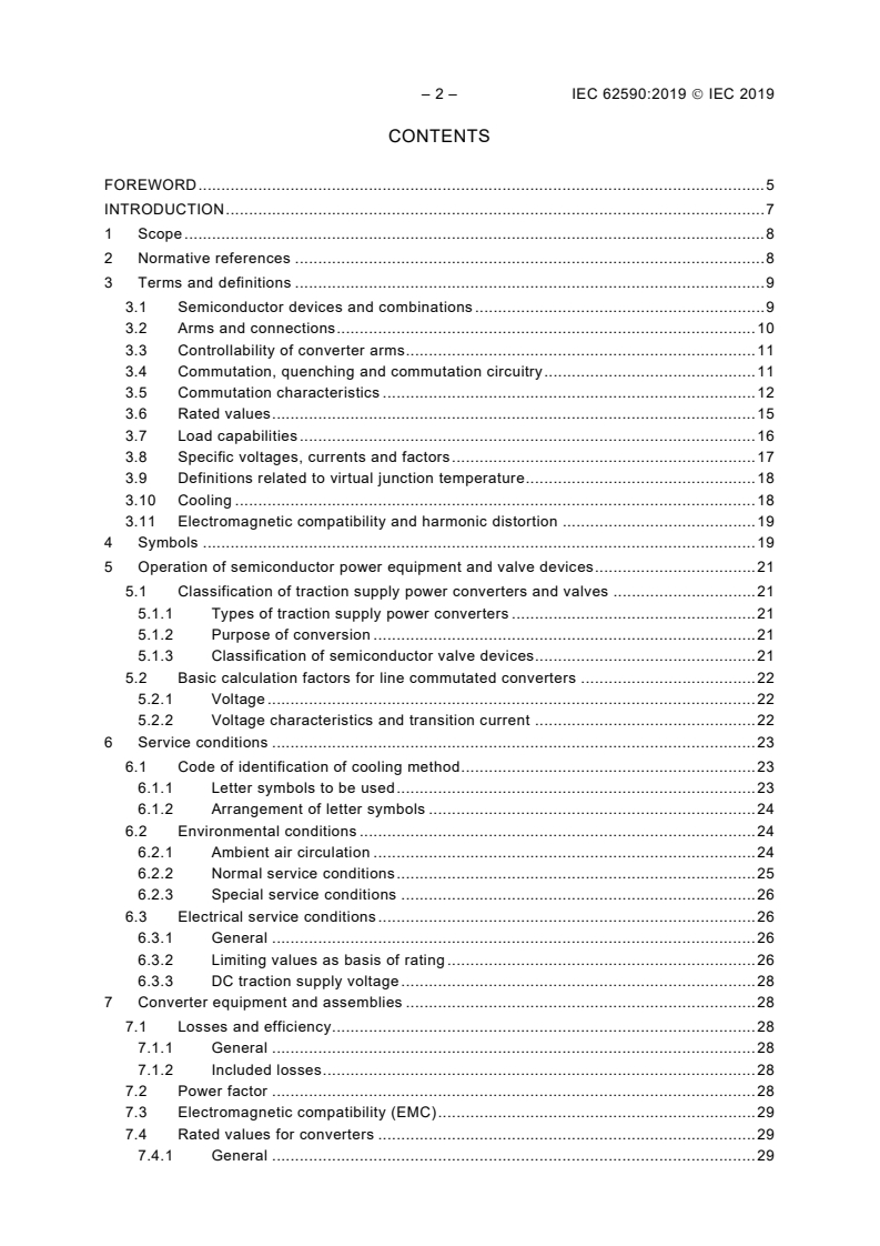
IEC 62590:2019 - Railway applications - Fixed installations - Electronic power converters for substations Released:8/23/2019
IEC 62590:2019 RLV - Railway applications - Fixed installations - Electronic power converters for substations Released:8/23/2019
IEC 62590:2019 - Applications ferroviaires - Installations fixes - Convertisseurs électroniques de puissance pour sous-stations/23/2019
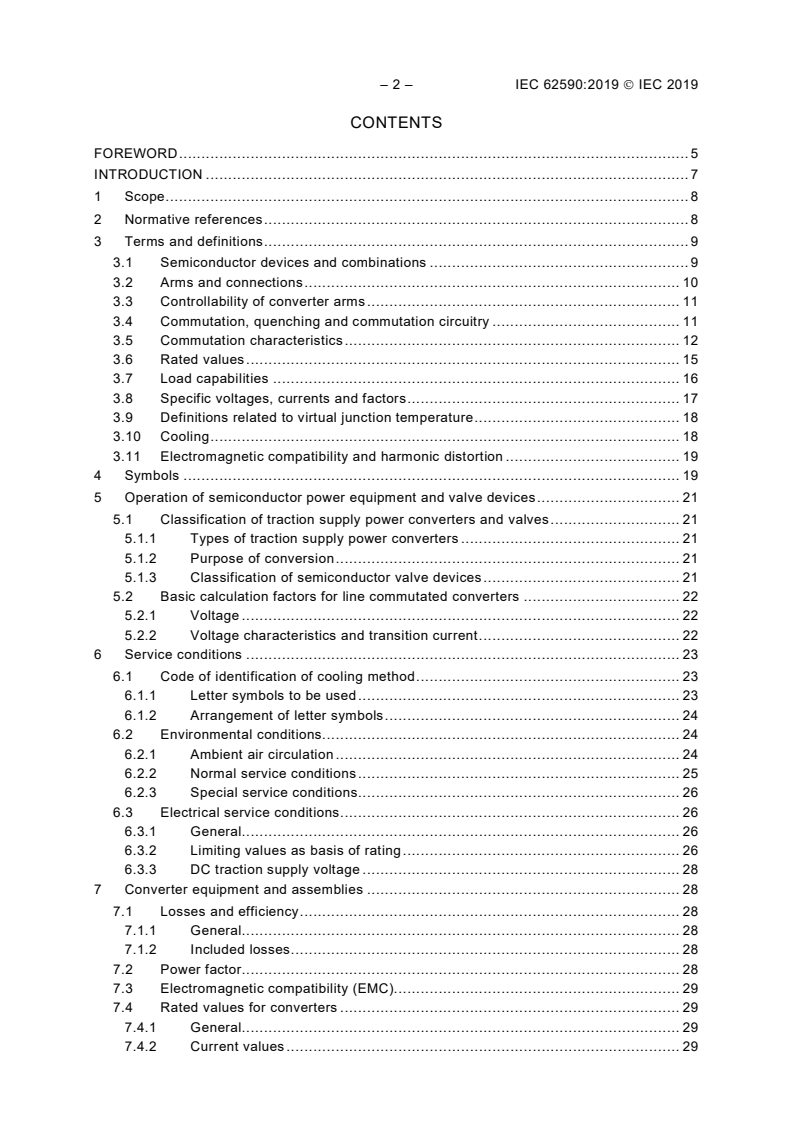
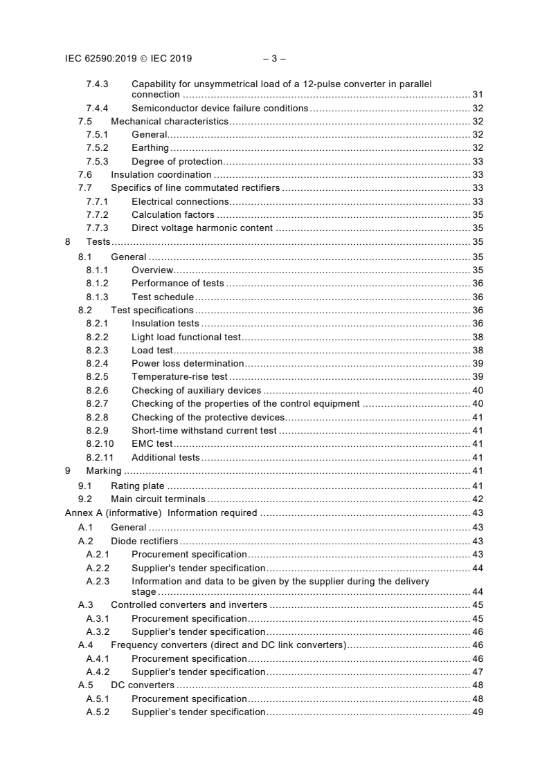
IEC 62590:2019 - Railway applications - Fixed installations - Electronic power converters for substations/23/2019
Overview
IEC 62590:2019 - "Railway applications - Fixed installations - Electronic power converters for substations" - specifies performance, rating and test requirements for fixed-installation electronic power converters used in traction power supply. This international standard covers converters employing controllable and non‑controllable electronic valves (controlled by current, voltage or light) and assumes non‑bistable devices operate in switched mode. It applies to railways and guided mass transit systems (tramways, light rail, elevated/underground railways, mountain railways, trolleybuses). Edition 2.0 (2019) cancels and replaces the 2010 edition and incorporates key updates including the addition of DC converters and corrections to clearance/withstand voltage rules.
Key topics and technical requirements
- Scope and classifications: Types of traction converters, valve device classifications and purposes (rectification, inversion, DC conversion).
- Rated values and load capabilities: Definitions for current, voltage and duty classes; guidance for unsymmetrical loading of parallel converters.
- Service conditions: Environmental and electrical service conditions, cooling codes and standardized duty classes for rating equipment.
- Insulation coordination and clearances: Insulation levels and revised clearance/withstand voltage requirements (correction from prior edition).
- Thermal management: Cooling method codes, temperature-rise testing and calculation of the virtual junction temperature (Annex B) for semiconductor device current capability.
- Electromagnetic compatibility (EMC) and harmonic distortion requirements for traction converters.
- Line‑commutated converter specifics: Connections, calculation factors and direct voltage harmonic content.
- Testing and verification: Test schedule and procedures including insulation tests, light-load and full-load functional tests, power‑loss determination, temperature‑rise, protective device checks, short‑time withstand and EMC tests (see Clause 8 and Table 7).
Practical applications and users
IEC 62590:2019 is essential for:
- Substation equipment manufacturers designing and producing traction converters and DC link systems.
- System integrators and design engineers specifying converter performance, cooling and insulation coordination for fixed installations.
- Procurement teams and asset owners (railway operators, transit authorities) preparing technical specifications and acceptance tests.
- Testing laboratories and certification bodies performing acceptance and type tests per the standard.
- Maintenance and safety engineers assessing failure modes, thermal limits and EMC compliance.
Practical use cases include specifying converter ratings for new substations, validating supplier tenders, verifying insulation and EMC performance, and ensuring thermal margins for semiconductor devices.
Related standards
- Based on EN 50328 (harmonization reference).
- Refer to other IEC documents for complementary topics (insulation, EMC, electrotechnical vocabulary) as indicated in the normative references of IEC 62590.
Keywords: IEC 62590:2019, electronic power converters, railway substations, traction power supply, DC converters, insulation coordination, EMC, virtual junction temperature, converter testing.
Relations
- Effective Date
- 26-Oct-2025
- Effective Date
- 26-Oct-2025
- Effective Date
- 26-Oct-2025
- Effective Date
- 26-Oct-2025
- Effective Date
- 10-Feb-2026
- Effective Date
- 05-Sep-2023
Buy Documents
IEC 62590:2019 - Railway applications - Fixed installations - Electronic power converters for substations Released:8/23/2019
IEC 62590:2019 RLV - Railway applications - Fixed installations - Electronic power converters for substations Released:8/23/2019
IEC 62590:2019 - Applications ferroviaires - Installations fixes - Convertisseurs électroniques de puissance pour sous-stations/23/2019
IEC 62590:2019 - Railway applications - Fixed installations - Electronic power converters for substations/23/2019
Get Certified
Connect with accredited certification bodies for this standard

IRIS Certification (UNIFE)
International Railway Industry Standard certification.

TÜV SÜD Rail GmbH
TÜV SÜD railway certification services.

Bureau Veritas Railway Certification
Railway and transportation certification.
Sponsored listings
Frequently Asked Questions
IEC 62590:2019 is a standard published by the International Electrotechnical Commission (IEC). Its full title is "Railway applications - Fixed installations - Electronic power converters for substations". This standard covers: IEC 62590:2019 specifies the requirements for the performance of all fixed installations electronic power converters, using controllable and/or non-controllable electronic valves, intended for traction power supply. The devices can be controlled by means of current, voltage or light. Non-bistable devices are assumed to be operated in the switched mode. This document applies to fixed installations of the following electric traction systems: - railways, - guided mass transport systems such as: tramways, light rail systems, elevated and underground railways, mountain railways, trolleybuses. This standard is based on EN 50328. This second edition cancels and replaces the first edition published in 2010. This edition includes the following significant technical changes with respect to the previous edition: a) Incorporation of DC converters. b) Correction of the clearances and withstand voltages due to erroneous use of PD in former edition. c) adaption of structure, adaption of vocabulary, removal of unused term and abbreviations.
IEC 62590:2019 specifies the requirements for the performance of all fixed installations electronic power converters, using controllable and/or non-controllable electronic valves, intended for traction power supply. The devices can be controlled by means of current, voltage or light. Non-bistable devices are assumed to be operated in the switched mode. This document applies to fixed installations of the following electric traction systems: - railways, - guided mass transport systems such as: tramways, light rail systems, elevated and underground railways, mountain railways, trolleybuses. This standard is based on EN 50328. This second edition cancels and replaces the first edition published in 2010. This edition includes the following significant technical changes with respect to the previous edition: a) Incorporation of DC converters. b) Correction of the clearances and withstand voltages due to erroneous use of PD in former edition. c) adaption of structure, adaption of vocabulary, removal of unused term and abbreviations.
IEC 62590:2019 is classified under the following ICS (International Classification for Standards) categories: 45.060.01 - Railway rolling stock in general. The ICS classification helps identify the subject area and facilitates finding related standards.
IEC 62590:2019 has the following relationships with other standards: It is inter standard links to IEC 62590-2-2:2026, IEC 62590-1:2025, IEC 62590-3-1:2022, IEC 62590-2-1:2025, prEN IEC 62590-3-1:2024, IEC 62590:2010. Understanding these relationships helps ensure you are using the most current and applicable version of the standard.
IEC 62590:2019 is available in PDF format for immediate download after purchase. The document can be added to your cart and obtained through the secure checkout process. Digital delivery ensures instant access to the complete standard document.
Standards Content (Sample)
IEC 62590 ®
Edition 2.0 2019-08
INTERNATIONAL
STANDARD
Railway applications – Fixed installations – Electronic power converters for
substations
All rights reserved. Unless otherwise specified, no part of this publication may be reproduced or utilized in any form
or by any means, electronic or mechanical, including photocopying and microfilm, without permission in writing from
either IEC or IEC's member National Committee in the country of the requester. If you have any questions about IEC
copyright or have an enquiry about obtaining additional rights to this publication, please contact the address below or
your local IEC member National Committee for further information.
IEC Central Office Tel.: +41 22 919 02 11
3, rue de Varembé info@iec.ch
CH-1211 Geneva 20 www.iec.ch
Switzerland
About the IEC
The International Electrotechnical Commission (IEC) is the leading global organization that prepares and publishes
International Standards for all electrical, electronic and related technologies.
About IEC publications
The technical content of IEC publications is kept under constant review by the IEC. Please make sure that you have the
latest edition, a corrigendum or an amendment might have been published.
IEC publications search - webstore.iec.ch/advsearchform Electropedia - www.electropedia.org
The advanced search enables to find IEC publications by a The world's leading online dictionary on electrotechnology,
variety of criteria (reference number, text, technical containing more than 22 000 terminological entries in English
committee,…). It also gives information on projects, replaced and French, with equivalent terms in 16 additional languages.
and withdrawn publications. Also known as the International Electrotechnical Vocabulary
(IEV) online.
IEC Just Published - webstore.iec.ch/justpublished
Stay up to date on all new IEC publications. Just Published IEC Glossary - std.iec.ch/glossary
details all new publications released. Available online and 67 000 electrotechnical terminology entries in English and
once a month by email. French extracted from the Terms and Definitions clause of
IEC publications issued since 2002. Some entries have been
IEC Customer Service Centre - webstore.iec.ch/csc collected from earlier publications of IEC TC 37, 77, 86 and
If you wish to give us your feedback on this publication or CISPR.
need further assistance, please contact the Customer Service
Centre: sales@iec.ch.
IEC 62590 ®
Edition 2.0 2019-08
INTERNATIONAL
STANDARD
Railway applications – Fixed installations – Electronic power converters for
substations
INTERNATIONAL
ELECTROTECHNICAL
COMMISSION
ICS 45.060.01 ISBN 978-2-8322-7066-0
– 2 – IEC 62590:2019 IEC 2019
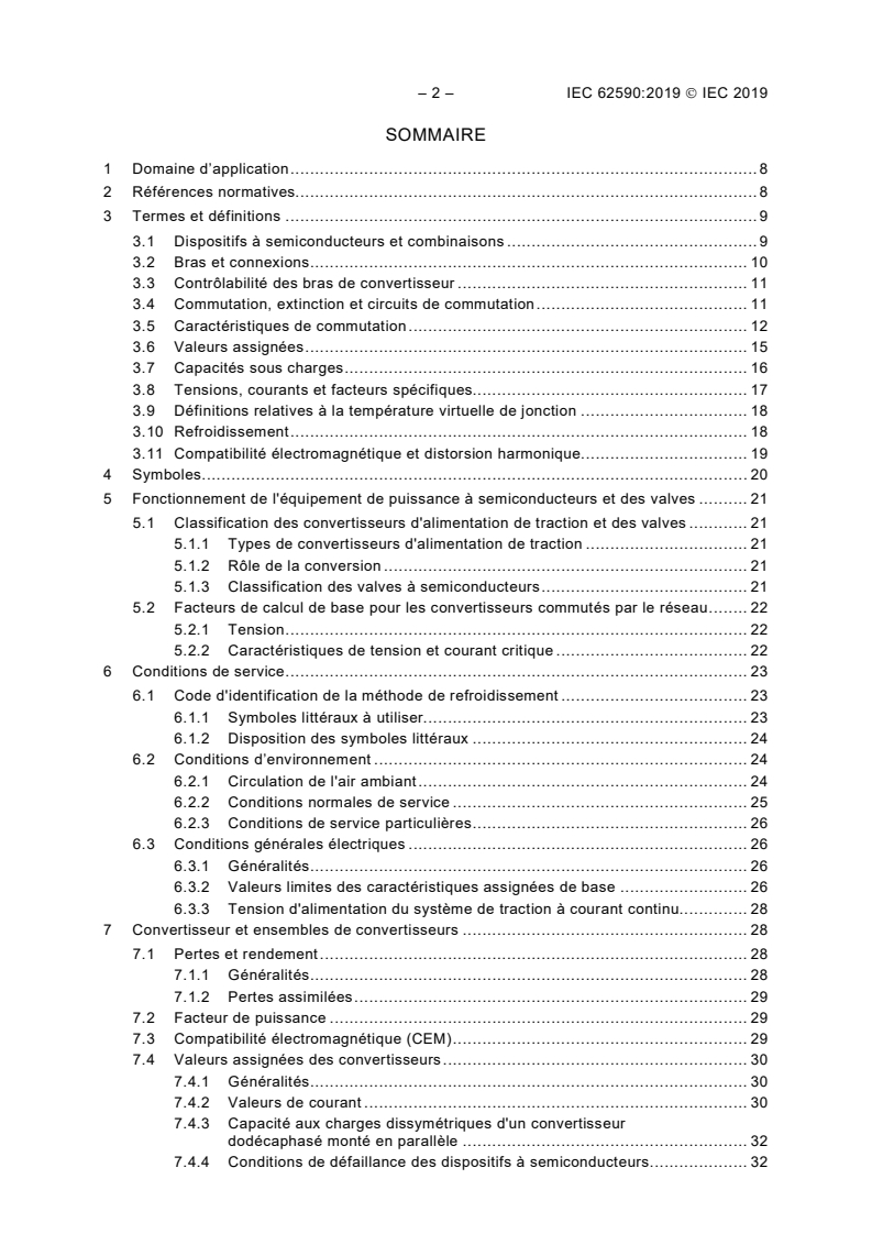
CONTENTS
FOREWORD . 5
INTRODUCTION . 7
1 Scope . 8
2 Normative references . 8
3 Terms and definitions . 9
3.1 Semiconductor devices and combinations . 9
3.2 Arms and connections . 10
3.3 Controllability of converter arms . 11
3.4 Commutation, quenching and commutation circuitry . 11
3.5 Commutation characteristics . 12
3.6 Rated values . 15
3.7 Load capabilities . 16
3.8 Specific voltages, currents and factors . 17
3.9 Definitions related to virtual junction temperature . 18
3.10 Cooling . 18
3.11 Electromagnetic compatibility and harmonic distortion . 19
4 Symbols . 19
5 Operation of semiconductor power equipment and valve devices . 21
5.1 Classification of traction supply power converters and valves . 21
5.1.1 Types of traction supply power converters . 21
5.1.2 Purpose of conversion . 21
5.1.3 Classification of semiconductor valve devices . 21
5.2 Basic calculation factors for line commutated converters . 22
5.2.1 Voltage . 22
5.2.2 Voltage characteristics and transition current . 22
6 Service conditions . 23
6.1 Code of identification of cooling method . 23
6.1.1 Letter symbols to be used . 23
6.1.2 Arrangement of letter symbols . 24
6.2 Environmental conditions . 24
6.2.1 Ambient air circulation . 24
6.2.2 Normal service conditions . 25
6.2.3 Special service conditions . 26
6.3 Electrical service conditions . 26
6.3.1 General . 26
6.3.2 Limiting values as basis of rating . 26
6.3.3 DC traction supply voltage . 28
7 Converter equipment and assemblies . 28
7.1 Losses and efficiency . 28
7.1.1 General . 28
7.1.2 Included losses . 28
7.2 Power factor . 28
7.3 Electromagnetic compatibility (EMC) . 29
7.4 Rated values for converters . 29
7.4.1 General . 29
7.4.2 Current values . 29
7.4.3 Capability for unsymmetrical load of a 12-pulse converter in parallel
connection . 31
7.4.4 Semiconductor device failure conditions . 32
7.5 Mechanical characteristics . 32
7.5.1 General . 32
7.5.2 Earthing . 32
7.5.3 Degree of protection . 33
7.6 Insulation coordination . 33
7.7 Specifics of line commutated rectifiers . 33
7.7.1 Electrical connections . 33
7.7.2 Calculation factors . 35
7.7.3 Direct voltage harmonic content . 35
8 Tests . 35
8.1 General . 35
8.1.1 Overview . 35
8.1.2 Performance of tests . 36
8.1.3 Test schedule . 36
8.2 Test specifications . 36
8.2.1 Insulation tests . 36
8.2.2 Light load functional test . 38
8.2.3 Load test . 38
8.2.4 Power loss determination . 39
8.2.5 Temperature-rise test . 39
8.2.6 Checking of auxiliary devices . 40
8.2.7 Checking of the properties of the control equipment . 40
8.2.8 Checking of the protective devices . 41
8.2.9 Short-time withstand current test . 41
8.2.10 EMC test . 41
8.2.11 Additional tests . 41
9 Marking . 41
9.1 Rating plate . 41
9.2 Main circuit terminals . 42
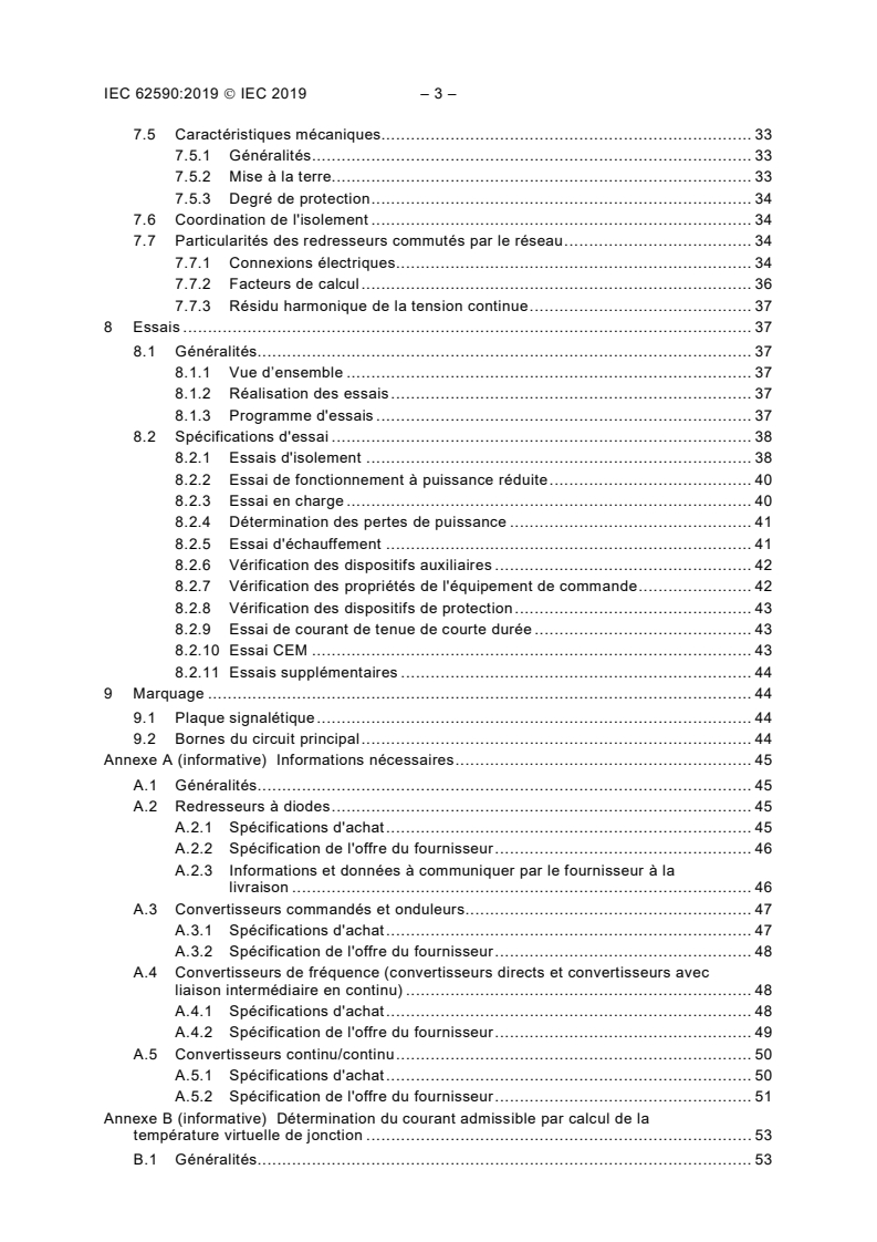
Annex A (informative) Information required . 43
A.1 General . 43
A.2 Diode rectifiers . 43
A.2.1 Procurement specification . 43
A.2.2 Supplier's tender specification . 44
A.2.3 Information and data to be given by the supplier during the delivery
stage . 44
A.3 Controlled converters and inverters. 45
A.3.1 Procurement specification . 45
A.3.2 Supplier's tender specification . 46
A.4 Frequency converters (direct and DC link converters) . 46
A.4.1 Procurement specification . 46
A.4.2 Supplier's tender specification . 47
A.5 DC converters . 48
A.5.1 Procurement specification . 48
A.5.2 Supplier’s tender specification . 49
– 4 – IEC 62590:2019 IEC 2019
Annex B (informative) Determination of the current capability through calculation of
the virtual junction temperature . 51
B.1 General . 51
B.2 Approximation of the shape of power pulses applied to the semiconductor
device . 51
B.3 Superposition method for the calculation of temperature . 52
B.4 Calculation of virtual junction temperature for continuous load . 53
B.4.1 General . 53
B.4.2 Calculation of mean value of virtual junction temperature . 53
B.4.3 Calculation of maximum instantaneous virtual junction temperature . 53
B.5 Calculation of virtual junction temperature for cyclic loads . 54
B.6 Examples for typical applications . 55
Annex C (informative) Index of definitions . 57
Bibliography . 59
Figure 1 – Illustration of angles . 14
Figure 2 – Voltage regulation . 23
Figure 3 – AC voltage waveform . 27
Figure B.1 – Approximation of the shape of power pulses . 52
Figure B.2 – Calculation of the virtual junction temperature for continuous load . 53
Figure B.3 – Calculation of the virtual junction temperature for cyclic load . 54
Table 1 – Letter symbols for cooling mediums and heat transfer agents . 23
Table 2 – Letter symbols for methods of circulation . 23
Table 3 – Standardized duty classes . 30
Table 4 – Semiconductor device failure conditions . 32
Table 5 – Insulation levels for AC/DC and DC converters . 33
Table 6 – Connections and calculation factors for line commutated converters . 34
Table 7 – Summary of tests . 36
Table 8 – Insulation levels for AC/DC and DC converters . 38
Table B.1 – Examples for typical applications . 55
INTERNATIONAL ELECTROTECHNICAL COMMISSION
____________
RAILWAY APPLICATIONS – FIXED INSTALLATIONS –
ELECTRONIC POWER CONVERTERS FOR SUBSTATIONS
FOREWORD
1) The International Electrotechnical Commission (IEC) is a worldwide organization for standardization comprising
all national electrotechnical committees (IEC National Committees). The object of IEC is to promote international
co-operation on all questions concerning standardization in the electrical and electronic fields. To this end and
in addition to other activities, IEC publishes International Standards, Technical Specifications, Technical Reports,
Publicly Available Specifications (PAS) and Guides (hereafter referred to as “IEC Publication(s)”). Their
preparation is entrusted to technical committees; any IEC National Committee interested in the subject dealt with
may participate in this preparatory work. International, governmental and non-governmental organizations liaising
with the IEC also participate in this preparation. IEC collaborates closely with the International Organization for
Standardization (ISO) in accordance with conditions determined by agreement between the two organizations.
2) The formal decisions or agreements of IEC on technical matters express, as nearly as possible, an international
consensus of opinion on the relevant subjects since each technical committee has representation from all
interested IEC National Committees.
3) IEC Publications have the form of recommendations for international use and are accepted by IEC National
Committees in that sense. While all reasonable efforts are made to ensure that the technical content of IEC
Publications is accurate, IEC cannot be held responsible for the way in which they are used or for any
misinterpretation by any end user.
4) In order to promote international uniformity, IEC National Committees undertake to apply IEC Publications
transparently to the maximum extent possible in their national and regional publications. Any divergence between
any IEC Publication and the corresponding national or regional publication shall be clearly indicated in the latter.
5) IEC itself does not provide any attestation of conformity. Independent certification bodies provide conformity
assessment services and, in some areas, access to IEC marks of conformity. IEC is not responsible for any
services carried out by independent certification bodies.
6) All users should ensure that they have the latest edition of this publication.
7) No liability shall attach to IEC or its directors, employees, servants or agents including individual experts and
members of its technical committees and IEC National Committees for any personal injury, property damage or
other damage of any nature whatsoever, whether direct or indirect, or for costs (including legal fees) and
expenses arising out of the publication, use of, or reliance upon, this IEC Publication or any other IEC Publications.
8) Attention is drawn to the Normative references cited in this publication. Use of the referenced publications is
indispensable for the correct application of this publication.
9) Attention is drawn to the possibility that some of the elements of this IEC Publication may be the subject of patent
rights. IEC shall not be held responsible for identifying any or all such patent rights.
International Standard IEC 62590 has been prepared by IEC technical committee 9: Electrical
equipment and systems for railways.
This standard is based on EN 50328.
This second edition cancels and replaces the first edition published in 2010. This edition
constitutes a technical revision.
This edition includes the following significant technical changes with respect to the previous
edition:
a) Incorporation of DC converters.
b) Correction of the clearances and withstand voltages due to erroneous use of PD in former
edition.
c) Adaption to current ISO/IEC directive part 2, adaption of structure, adaption of vocabulary,
removal of unused term and abbreviations.
The text of this standard is based on the following documents:
– 6 – IEC 62590:2019 IEC 2019
FDIS Report on voting
9/2502/FDIS 9/2516/RVD
Full information on the voting for the approval of this International Standard can be found in the
report on voting indicated in the above table.
This document has been drafted in accordance with the ISO/IEC Directives, Part 2.
The committee has decided that the contents of this document will remain unchanged until the
stability date indicated on the IEC website under "http://webstore.iec.ch" in the data related to
the specific document. At this date, the document will be
• reconfirmed,
• withdrawn,
• replaced by a revised edition, or
• amended.
A bilingual version of this publication may be issued at a later date.
INTRODUCTION
Semiconductor converters for traction power supply differ from other converters for industrial
use due to special electrical service conditions and due to the large range of load variation and
the peculiar characteristics of the load.
For these reasons IEC 60146-1-1 does not fully cover the requirements of railway applications
and the decision was taken to have a specific standard for this use.
Converter transformers for fixed installations of railway applications are covered by IEC 62695.
Harmonization of the rated values and tests of the whole converter group are covered by
IEC 62589.
– 8 – IEC 62590:2019 IEC 2019
RAILWAY APPLICATIONS – FIXED INSTALLATIONS –
ELECTRONIC POWER CONVERTERS FOR SUBSTATIONS
1 Scope
This document specifies the requirements for the performance of all fixed installations electronic
power converters, using controllable and/or non-controllable electronic valves, intended for
traction power supply.
The devices can be controlled by means of current, voltage or light. Non-bistable devices are
assumed to be operated in the switched mode.
This document applies to fixed installations of the following electric traction systems:
• railways,
• guided mass transport systems such as: tramways, light rail systems, elevated and
underground railways, mountain railways, trolleybusses.
This document does not apply to:
• cranes, transportable platforms and similar transportation equipment on rails,
• suspended cable cars,
• funicular railways.
This document applies to diode rectifiers, controlled rectifiers, DC converters, inverters and
frequency converters.
The equipment covered in this document is the converter itself.
2 Normative references
The following documents are referred to in the text in such a way that some or all of their content
constitutes requirements of this document. For dated references, only the edition cited applies.
For undated references, the latest edition of the referenced document (including any
amendments) applies.
IEC 60050-811:2017, International electrotechnical vocabulary – Part 811: Electric traction
IEC 60146 (all parts), Semiconductor convertors
IEC TR 60146-1-2:2011, Semiconductor converters – General requirements and line
commutated converters – Part 1-2: Application guide
IEC 60529:1989, Degrees of protection provided by enclosures (IP Code)
IEC 60721 (all parts), Classification of environmental conditions
IEC 60721-3-3:1994, Classification of environmental conditions – Part 3: Classification of
groups of environmental parameters and their severities – Section 3: Stationary use at
weatherprotected locations
AMD1:1995
AMD2:1996
IEC 60721-3-4:1995, Classification of environmental conditions – Part 3: Classification of
groups of environmental parameters and their severities – Section 4: Stationary use at non-
weatherprotected locations
AMD1:1996
IEC 60850:2014, Railway applications – Supply voltages of traction systems
IEC 61000-2-4:2002, Electromagnetic compatibility (EMC) – Part 2-4: Environment –
Compatibility levels in industrial plants for low-frequency conducted disturbances
IEC 61000-2-12:2003, Electromagnetic compatibility (EMC) – Part 2-12: Environment –
Compatibility levels for low-frequency conducted disturbances and signalling in public medium-
voltage power supply systems
IEC 61992-7-1:2006, Railway applications – Fixed installations – DC switchgear – Part 7-1:
Measurement, control and protection devices for specific use in DC traction systems –
Application guide
IEC 62236 (all parts), Railway applications – Electromagnetic compatibility
IEC 62236-5:2018, Railway applications – Electromagnetic compatibility – Part 5: Emission and
immunity of fixed power supply installations and apparatus
IEC 62497-1:2010, Railway applications – Insulation coordination – Part 1: Basic requirements
– Clearances and creepage distances for all electrical and electronic equipment
3 Terms and definitions
For the purposes of this document, the following terms and definitions apply.
ISO and IEC maintain terminological databases for use in standardization at the following
addresses:
• IEC Electropedia: available at http://www.electropedia.org/
• ISO Online browsing platform: available at http://www.iso.org/obp
NOTE An alphabetical index is given in Annex C.
3.1 Semiconductor devices and combinations
3.1.1
semiconductor device
device whose essential characteristics are due to the flow of charge carriers within a
semiconductor
[SOURCE: IEC 60050-521: 2002, 521-04-01, modified – note omitted]
3.1.2
(valve device) stack
a single structure of one or more electronic valve devices with its (their) associated mounting(s)
and auxiliaries if any
[SOURCE: IEC 60050-551:1998, 551-14-12]
– 10 – IEC 62590:2019 IEC 2019
3.1.3
(valve device) assembly
an electrically and mechanically combined assembly of electronic valve devices or stacks,
complete with all its connections and auxiliaries in its own mechanical structure
[SOURCE: IEC 60050-551:1998, 551-14-13]
3.1.4
electronic power converter
operative unit for power conversion comprising one or more assemblies of semiconductor
devices
Note 1 to entry: The transformers are described in IEC 62695
[SOURCE: IEC 60050-551:1998, 551-12-01, modified – “electronic” has been omitted.
“electronic valve devices, transformers and filters if necessary and auxiliaries if any” has been
replaced with “assemblies of semiconductor devices”. The note 1 to entry has been omitted.]
3.1.5
trigger equipment
equipment which provides suitable trigger pulses from a control signal for controllable valve
devices in a converter or power switch including timing or phase shifting circuits, pulse
generating circuits and usually power supply circuits
3.1.6
system control equipment
equipment associated with a converter equipment or system which performs automatic
adjustment of the output characteristics as a function of a controlled quantity
3.2 Arms and connections
3.2.1
(valve) arm
a part of the circuit of an electronic power converter or switch bounded by any two AC or DC
terminals and including one or more simultaneously conducting electronic valve devices
connected together and other components if any
[SOURCE: IEC 60050-551:1998, 551-15-01]
3.2.2
principal arm
a valve arm involved in the major transfer of power from one side of the converter or electronic
switch to the other
Note 1 to entry: Depending on the mode of operation a principal arm may act as an auxiliary arm or vice versa.
[SOURCE: IEC 60050-551:1998, 551-15-02]
3.2.3
converter connection
the electrical arrangement of valve arms and other components essential for the function of the
main power circuit of a converter
[SOURCE: IEC 60050-551:1998, 551-15-10]
3.2.4
uniform connection
a connection with either all principal arms controllable or all principal arms non-controllable
[SOURCE: IEC 60050-551:1998, 551-15-15]
3.2.5
non-uniform connection
a connection with both controllable and non-controllable principal arms
[SOURCE: IEC 60050-551:1998, 551-15-18]
3.2.6
parallel connection
connection in which two or more converters are connected in such a way that their currents add
3.3 Controllability of converter arms
3.3.1
controllable valve device
a valve device the current path of which is bistably controlled in its conducting direction
[SOURCE: IEC 60050-551:1998, 551-14-03]
3.4 Commutation, quenching and commutation circuitry
3.4.1
commutation
in an electronic power converter the transfer of current from one conducting arm to the next to
conduct in sequence, without interruption of the current, both arms conducting simultaneously
during a finite time interval
[SOURCE: IEC 60050-551:1998, 551-16-01]
3.4.2
quenching
the termination of current flow in an arm without commutation
[SOURCE: IEC 60050-551:1998, 551-16-19]
3.4.3
direct commutation
a commutation between two principal arms without transfer through any auxiliary arms
[SOURCE: IEC 60050-551:1998, 551-16-09]
3.4.4
indirect commutation
a series of commutations from one principal arm to another or back to the original one by
successive commutations via one or more auxiliary arms
[SOURCE: IEC 60050-551:1998, 551-16-10]
3.4.5
line commutation
an external commutation where the commutating voltage is supplied by the line
Note 1 to entry: In the text commutated is used instead of commutation.
[SOURCE: IEC 60050-551:1998, 551-16-12]
– 12 – IEC 62590:2019 IEC 2019
3.4.6
load commutation
an external commutation where the commutating voltage is taken from a load other than the
line
[SOURCE: IEC 60050-551:1998, 551-16-13]
3.4.7
self commutation
a commutation where the commutating voltage is supplied by components within the converter
or the electronic switch
Note 1 to entry: In the text commutated is used instead of commutation
[SOURCE: IEC 60050-551:1998, 551-16-15]
3.5 Commutation characteristics
3.5.1
commutating voltage
the voltage which causes the current to commutate
[SOURCE: IEC 60050-551:1998, 551-16-02]
3.5.2
angle of overlap
u
duration of the commutation interval between a pair of principal arms, expressed in angular
measure, where the two arms carry current
[SOURCE: IEC 60050-551:1998, 551-16-05, modified – “duration of”, “between a pair of
principal arms,” and “,where the two arms carry current” have been added.]
3.5.3
commutating group
a group of principal arms which commutate cyclically among themselves without intermediate
commutation of the current to other principal arms
[SOURCE: IEC 60050-551:1998, 551-16-08]
3.5.4
commutation number
q
number of commutations from one principal arm to another, occurring during one period of the
alternating voltage in each commutating group
[SOURCE: IEC 60050-551:1998, 551-17-03, modified – “during one elementary period” has
been replaced with “occurring during one period of the alternating voltage”.]
3.5.5
pulse number
p
number of non-simultaneous symmetrical direct or indirect commutations from one principal arm
to another, during one period of the alternating voltage
[SOURCE: IEC 60050-551:1998, 551-17-01, modified – “which occur during one elementary
period” has been replaced with “during one period of the alternating voltage”.]
3.5.6
trigger delay angle
α
time expressed in angular measure by which the trigger pulse is delayed with respect to the
reference instant (see Figure 1)
Note 1 to entry: For line, machine or load commutated converters the reference instant is the zero crossing instant
of the commutating voltage.
For AC controllers it is the zero crossing instant of the supply voltage.
For AC controllers with inductive load, the trigger delay angle is the sum of the phase shift and the current delay
angle
[SOURCE: IEC 60050-551:1998, 551-16-33, modified – The end of the definition “in the case
of phase control” has been removed. The note 1 to entry has been changed.]
– 14 – IEC 62590:2019 IEC 2019
Figure 1 – Illustration of angles
3.5.7
trigger advance angle
β
(see Figure 1)
the time expressed in angular measure by which the trigger pulse is advanced with respect to
the reference instant
Note 1 to entry: With line, machine or load commutated converters the reference instant is the zero crossing instant
of the commutating voltage.
[SOURCE: IEC 60050-551:1998, 551-16-34]
3.5.8
extinction angle
γ
time, expressed in angular measure, between the moment when the current of the arm falls to
zero and the moment when the arm is required to withstand steeply rising off-state voltage
3.6 Rated values
3.6.1
rated value
value of a quantity used for specification purposes, established for a specified set of operating
conditions of a component, device, equipment, or system
[SOURCE: IEC 60050-151:2001, 151-16-08]
3.6.2
rated frequency
f
N
frequency on either side of the converter for the conversion of which the converter group is
designed to operate
3.6.3
nominal voltage
U
n
voltage by which a converter is designated
Note 1 to entry: The standardized values of nominal voltages are given in IEC 60850.
3.6.4
rated insulation voltage
U
Nm
rated value of the RMS withstand voltage assigned by the manufacturer to the equipment or to
a part of it, characterizing the specified (long-term) withstand capability of its insulation
Note 1 to entry: Standardized values of rated insulation voltages are given in IEC 62497.
[SOURCE: IEC 60050-312: 2014, 312-06-02, modified – note 1 to entry removed]
3.6.5
rated AC voltage on the supply side of a converter
U
Nv
RMS value of the no-load voltage between vectorially consecutive commutating phase terminals
of a commutating group
3.6.6
rated AC voltage on the traction side of a converter
U
Nt
RMS value of the no-load voltage on the traction side of a frequency converter
3.6.7
rated direct voltage
U
Nd
specified value of the direct voltage between the DC terminals of the converter assembly at
basic direct current
Note 1 to entry: This value is the mean value of the direct voltage.
Note 2 to entry: A converter may have more than one rated voltage or a rated direct voltage range.
– 16 – IEC 62590:2019 IEC 2019
Note 3 to entry: The rated direct voltage of a converter depends on the characteristics of the transformer and a
guaranteed value of rated direct voltage is valid only together with the transformer (see IEC 62589).
3.6.8
basic service current on the supply side of a converter
I
Bv
RMS value of the AC current, containing all harmonics, on the supply side of a converter at
basic current on the DC side
Note 1 to entry: For polyphase equipment, this value is computed from the basic direct current on the basis of
rectangular shaped currents, 120° conducting, of the converter elements. For single phase equipment, the basis of
calculation must be specified.
3.6.9
rated current on the traction side of a frequency converter
I
Nt
RMS value of the AC current on the traction side of a frequency converter under rated conditions
3.6.10
basic current
I
B
mean value of the current for specified load and service conditions
3.6.11
basic direct current
I
Bd
mean value of the direct current for specified load and service conditions
Note 1 to entry: Together with a duty class I is considered as the 1,0 p.u. value, to which other values of I are
Bd d
compared.
3.7 Load capabilities
3.7.1
duty class
tabled representation of current capability and test values for standard design converters in
terms of current values and duration selected to represent a characteristic group of practical
applications
Note 1 to entry: The current values are expressed in per unit of the basic direct current I
B.
3.7.2
load cycle
conventional representation of the current demand to a converter group
Note 1 to entry: The current values are expressed in A or in per unit of I
B.
Note 2 to entry: The load cycle shows the repetitive variation of the loads with time and, hence, the overloads and
underloads the converter group is expected to carry, as well as, for the transformers, the duration and intervals
assumed.
[SOURCE: IEC 60050-881: 2017, 811-28-38 modified – The note 1 to entry has been changed.]
3.7.3
rated DC power
delivered power at working point of basic direct current I
Bd
3.7.4
power efficiency
ratio of the output power to the input power of the converter
3.8 Specific voltages, currents and factors
3.8.1
ideal no-load direct voltage
U
di
theoretical no-load mean direct voltage of a converter, assuming no reduction by phase control,
no voltage drop in the assemblies and no voltage rise at small loads
[SOURCE: IEC 60050-551:1998, 551-17-15, modified – “mean” has been added. “AC/DC” has
been removed. “no threshold voltages of electronic valve devices” has been replaced with “no
voltage drop in the assemblies“.]
3.8.2
controlled ideal no-load direct voltage
U
diα
theoretical no-load direct voltage of an AC/DC converter corresponding to a specified trigger
delay angle assuming no threshold voltages of electronic valve devices and no voltage rise at
small loads
[SOURCE: IEC 60050-551:1998, 551-17-16]
3.8.3
conventional no-load direct voltage
U
d0
mean value of the direct voltage which would be obtained by extrapolating the direct
voltage/current characteristic for continuous direct current back to zero current
Note 1 to entry: U is equal to the sum of U and the no-load voltage drop in the assembly.
di d0
[SOURCE: IEC 60050-551:1998, 551-17-17, modified – “from the region of continuous flow of
direct current to zero current at zero trigger delay angle, i.e. without phase control” has been
replaced with “for continuous direct current back to zero current“.]
3.8.4
real no-load direct voltage
U
d00
actual mean direct voltage at zero direct current
[SOURCE: IEC 60050-551:1998, 551-17-19]
3.8.5
ideal crest no-load voltage
U
iM
no-load voltage between the end terminals of an arm neglecting internal and external voltage
surge and voltage drop in valves
3.8.6
transition current
mean direct current of a converter connection when the direct current of the commutating
groups becomes intermittent when decreasing the current
[SOURCE: IEC 60050-551:1998, 551-17-20, modified – “commutation” has been replaced with
“commutating“]
– 18 – IEC 62590:2019 IEC 2019
3.8.7
direct voltage drop
difference between the conventional no-load direct voltage and the direct voltage at basic direct
current, at the same current delay angle, excluding the correction effect of stabilizing means if
any
Note 1 to entry: The nature of the DC circuit (for example capacitors, voltage sources) can affect the voltage drop
significantly. Where this is the case, special consideration is required.
3.8.8
total power factor
λ
active power
λ=
apparent power
3.8.9
power factor of the fundamental wave or displacement factor
cos ϕ
active power of the fundamental wave
cosϕ =
apparent power of the fundamental wave
3.9 Definitions related to virtual junction temperature
3.9.1
thermal resistance
R
th
quotient of the difference between the virtual temperature of the device and the temperature of
a stated external reference point, by the steady state power dissipation in the device
[SOURCE: IEC 60050-521:2002, 521-05-13]
3.9.2
transient thermal impedance
Z
th
quotient of the variation of the temperature difference, reached at the end of a time interval
between the virtual junction temperature and the temperature at a specified external reference
point and the step function change of power dissipation at the beginning of the same time
interval causing the change of temperature
Note 1 to entry: The transient thermal impedance is given in a characteristic curve as a function of the time interval.
3.9.3
virtual junction temperature
Θ
j
calculated temperature within the semiconductor material which is based on a simplified
representation of the thermal and electrical behaviour of a semiconductor device
3.10 Cooling
3.10.1
cooling medium
liquid (for example water) or gas (for example air) which removes the heat from the equipment
3.10.2
heat transfer agent
liquid (for example water) or gas (for example air) within the equipment to transfer the heat from
its source to a heat exchanger from where the heat is removed by the cooling medium
3.10.3
direct cooling
method of cooling by which the cooling medium is in direct contact with the parts of the
equipment to be cooled, i.e. no heat transfer agent is used
3.10.4
indirect cooling
method of cooling in which a heat transfer agent is used to transfer heat from the part to be
cooled to the cooling medium
3.10.5
natural circulation
convection
method of circulating the cooling medium or heat transfer agent which uses the change of
volumetric mass (density) with temperature
3.10.6
forced circulation
forced cooling
method of circulating the cooling medium or heat transfer agent by means of blower(s), fan(s)
or pump(s)
3.10.7
thermal equilibrium
steady-state temperature condition reached by a component of a converter under specified
conditions of load and cooling
Note 1 to entry: The steady-state temperatures are in general different for different components. The times
necessary to establish steady-state are also different and proportional to the thermal time constants.
3.11 Electromagnetic compatibility and harmonic distortion
3.11.1
electrical disturbance
any variation of an electrical quantity, beyond specified limits, which can be the cause of a loss
of performance or an interruption of service or damage
3.11.2
immunity level
specified value of an electrical disturbance below which a converter is designed to me
...
IEC 62590 ®
Edition 2.0 2019-08
REDLINE VERSION
INTERNATIONAL
STANDARD
colour
inside
Railway applications – Fixed installations – Electronic power converters for
substations
All rights reserved. Unless otherwise specified, no part of this publication may be reproduced or utilized in any form
or by any means, electronic or mechanical, including photocopying and microfilm, without permission in writing from
either IEC or IEC's member National Committee in the country of the requester. If you have any questions about IEC
copyright or have an enquiry about obtaining additional rights to this publication, please contact the address below or
your local IEC member National Committee for further information.
IEC Central Office Tel.: +41 22 919 02 11
3, rue de Varembé info@iec.ch
CH-1211 Geneva 20 www.iec.ch
Switzerland
About the IEC
The International Electrotechnical Commission (IEC) is the leading global organization that prepares and publishes
International Standards for all electrical, electronic and related technologies.
About IEC publications
The technical content of IEC publications is kept under constant review by the IEC. Please make sure that you have the
latest edition, a corrigendum or an amendment might have been published.
IEC publications search - webstore.iec.ch/advsearchform Electropedia - www.electropedia.org
The advanced search enables to find IEC publications by a The world's leading online dictionary on electrotechnology,
variety of criteria (reference number, text, technical containing more than 22 000 terminological entries in English
committee,…). It also gives information on projects, replaced and French, with equivalent terms in 16 additional languages.
and withdrawn publications. Also known as the International Electrotechnical Vocabulary
(IEV) online.
IEC Just Published - webstore.iec.ch/justpublished
Stay up to date on all new IEC publications. Just Published IEC Glossary - std.iec.ch/glossary
details all new publications released. Available online and 67 000 electrotechnical terminology entries in English and
once a month by email. French extracted from the Terms and Definitions clause of
IEC publications issued since 2002. Some entries have been
IEC Customer Service Centre - webstore.iec.ch/csc collected from earlier publications of IEC TC 37, 77, 86 and
If you wish to give us your feedback on this publication or CISPR.
need further assistance, please contact the Customer Service
Centre: sales@iec.ch.
IEC 62590 ®
Edition 2.0 2019-08
REDLINE VERSION
INTERNATIONAL
STANDARD
colour
inside
Railway applications – Fixed installations – Electronic power converters for
substations
INTERNATIONAL
ELECTROTECHNICAL
COMMISSION
ICS 45.060.01 ISBN 978-2-8322-7357-9
– 2 – IEC 62590:2019 RLV IEC 2019
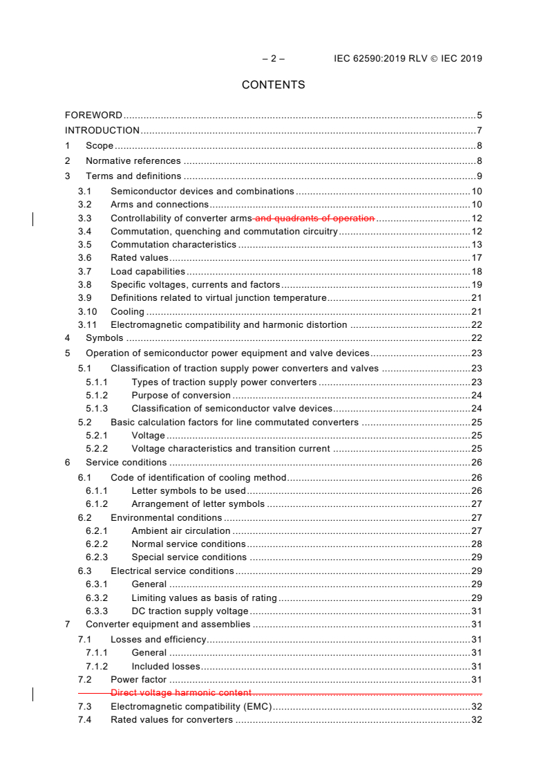
CONTENTS
FOREWORD . 5
INTRODUCTION . 7
1 Scope . 8
2 Normative references . 8
3 Terms and definitions . 9
3.1 Semiconductor devices and combinations . 10
3.2 Arms and connections . 10
3.3 Controllability of converter arms and quadrants of operation . 12
3.4 Commutation, quenching and commutation circuitry . 12
3.5 Commutation characteristics . 13
3.6 Rated values . 17
3.7 Load capabilities . 18
3.8 Specific voltages, currents and factors . 19
3.9 Definitions related to virtual junction temperature . 21
3.10 Cooling . 21
3.11 Electromagnetic compatibility and harmonic distortion . 22
4 Symbols . 22
5 Operation of semiconductor power equipment and valve devices . 23
5.1 Classification of traction supply power converters and valves . 23
5.1.1 Types of traction supply power converters . 23
5.1.2 Purpose of conversion . 24
5.1.3 Classification of semiconductor valve devices . 24
5.2 Basic calculation factors for line commutated converters . 25
5.2.1 Voltage . 25
5.2.2 Voltage characteristics and transition current . 25
6 Service conditions . 26
6.1 Code of identification of cooling method . 26
6.1.1 Letter symbols to be used . 26
6.1.2 Arrangement of letter symbols . 27
6.2 Environmental conditions . 27
6.2.1 Ambient air circulation . 27
6.2.2 Normal service conditions . 28
6.2.3 Special service conditions . 29
6.3 Electrical service conditions . 29
6.3.1 General . 29
6.3.2 Limiting values as basis of rating . 29
6.3.3 DC traction supply voltage . 31
7 Converter equipment and assemblies . 31
7.1 Losses and efficiency . 31
7.1.1 General . 31
7.1.2 Included losses . 31
7.2 Power factor . 31
Direct voltage harmonic content .
7.3 Electromagnetic compatibility (EMC) . 32
7.4 Rated values for converters . 32
7.4.1 General . 32
7.4.2 Current values . 33
7.4.3 Capability for unsymmetrical load of a 12-pulse converter in parallel
connection . 35
7.4.4 Semiconductor device failure conditions . 35
7.5 Mechanical characteristics . 35
7.5.1 General . 35
7.5.2 Earthing . 36
7.5.3 Degree of protection . 36
7.6 Insulation coordination . 36
7.7 Specifics of line commutated rectifiers . 37
7.7.1 Electrical connections . 37
7.7.2 Calculation factors . 38
7.7.3 Direct voltage harmonic content . 39
8 Tests . 39
8.1 General . 39
8.1.1 Overview . 39
8.1.2 Performance of tests . 39
8.1.3 Test schedule . 40
8.2 Test specifications . 40
8.2.1 Insulation tests . 40
8.2.2 Light load functional test . 43
8.2.3 Load test . 43
8.2.4 Power loss determination . 43
8.2.5 Temperature-rise test . 43
8.2.6 Checking of auxiliary devices . 45
8.2.7 Checking of the properties of the control equipment . 45
8.2.8 Checking of the protective devices . 45
8.2.9 Short-time withstand current test . 45
8.2.10 EMC test . 46
8.2.11 Additional tests . 46
9 Marking . 46
9.1 Rating plate . 46
9.2 Main circuit terminals . 47
Annex A (informative) Information required . 48
A.1 General . 48
A.2 Diode rectifiers . 48
A.2.1 Procurement specification . 48
A.2.2 Supplier's tender specification . 49
A.2.3 Information and data to be given by the supplier during the delivery
stage . 49
A.3 Controlled converters and inverters. 50
A.3.1 Procurement specification . 50
A.3.2 Supplier's tender specification . 51
A.4 Frequency converters (direct and DC link converters) . 51
A.4.1 Procurement specification . 51
A.4.2 Supplier's tender specification . 52
A.5 DC converters . 53
A.5.1 Procurement specification . 53
– 4 – IEC 62590:2019 RLV IEC 2019
A.5.2 Supplier’s tender specification . 54
Annex B (informative) Determination of the current capability through calculation of
the virtual junction temperature . 56
B.1 General . 56
B.2 Approximation of the shape of power pulses applied to the semiconductor
device . 56
B.3 Superposition method for the calculation of temperature . 57
B.4 Calculation of virtual junction temperature for continuous load . 58
B.4.1 General . 58
B.4.2 Calculation of mean value of virtual junction temperature . 58
B.4.3 Calculation of maximum instantaneous virtual junction temperature . 58
B.5 Calculation of virtual junction temperature for cyclic loads . 59
B.6 Examples for typical applications . 60
Annex C (informative) Index of definitions . 62
Bibliography . 64
Figure 1 – Illustration of angles . 16
Figure 2 – Voltage drop regulation . 26
Figure 3 – AC voltage waveform . 30
Figure B.1 – Approximation of the shape of power pulses . 57
Figure B.2 – Calculation of the virtual junction temperature for continuous load . 58
Figure B.3 – Calculation of the virtual junction temperature for cyclic load . 59
Table 1 – Letter symbols for cooling mediums and heat transfer agents . 26
Table 2 – Letter symbols for methods of circulation . 26
Table 3 – Standardized duty classes . 33
Table 4 – Semiconductor device failure conditions . 35
Table 5 – Insulation levels for AC/DC and DC converters . 37
Table 6 – Connections and calculation factors for line commutated converters . 37
Table 7 – Summary of tests . 40
Table 8 – Insulation levels for AC/DC and DC converters . 42
Table B.1 – Examples for typical applications . 60
INTERNATIONAL ELECTROTECHNICAL COMMISSION
____________
RAILWAY APPLICATIONS – FIXED INSTALLATIONS –
ELECTRONIC POWER CONVERTERS FOR SUBSTATIONS
FOREWORD
1) The International Electrotechnical Commission (IEC) is a worldwide organization for standardization comprising
all national electrotechnical committees (IEC National Committees). The object of IEC is to promote international
co-operation on all questions concerning standardization in the electrical and electronic fields. To this end and
in addition to other activities, IEC publishes International Standards, Technical Specifications, Technical Reports,
Publicly Available Specifications (PAS) and Guides (hereafter referred to as “IEC Publication(s)”). Their
preparation is entrusted to technical committees; any IEC National Committee interested in the subject dealt with
may participate in this preparatory work. International, governmental and non-governmental organizations liaising
with the IEC also participate in this preparation. IEC collaborates closely with the International Organization for
Standardization (ISO) in accordance with conditions determined by agreement between the two organizations.
2) The formal decisions or agreements of IEC on technical matters express, as nearly as possible, an international
consensus of opinion on the relevant subjects since each technical committee has representation from all
interested IEC National Committees.
3) IEC Publications have the form of recommendations for international use and are accepted by IEC National
Committees in that sense. While all reasonable efforts are made to ensure that the technical content of IEC
Publications is accurate, IEC cannot be held responsible for the way in which they are used or for any
misinterpretation by any end user.
4) In order to promote international uniformity, IEC National Committees undertake to apply IEC Publications
transparently to the maximum extent possible in their national and regional publications. Any divergence between
any IEC Publication and the corresponding national or regional publication shall be clearly indicated in the latter.
5) IEC itself does not provide any attestation of conformity. Independent certification bodies provide conformity
assessment services and, in some areas, access to IEC marks of conformity. IEC is not responsible for any
services carried out by independent certification bodies.
6) All users should ensure that they have the latest edition of this publication.
7) No liability shall attach to IEC or its directors, employees, servants or agents including individual experts and
members of its technical committees and IEC National Committees for any personal injury, property damage or
other damage of any nature whatsoever, whether direct or indirect, or for costs (including legal fees) and
expenses arising out of the publication, use of, or reliance upon, this IEC Publication or any other IEC Publications.
8) Attention is drawn to the Normative references cited in this publication. Use of the referenced publications is
indispensable for the correct application of this publication.
9) Attention is drawn to the possibility that some of the elements of this IEC Publication may be the subject of patent
rights. IEC shall not be held responsible for identifying any or all such patent rights.
This redline version of the official IEC Standard allows the user to identify the changes
made to the previous edition. A vertical bar appears in the margin wherever a change has
been made. Additions are in green text, deletions are in strikethrough red text.
– 6 – IEC 62590:2019 RLV IEC 2019
International Standard IEC 62590 has been prepared by IEC technical committee 9: Electrical
equipment and systems for railways.
This standard is based on EN 50328.
This second edition cancels and replaces the first edition published in 2010. This edition
constitutes a technical revision.
This edition includes the following significant technical changes with respect to the previous
edition:
a) Incorporation of DC converters.
b) Correction of the clearances and withstand voltages due to erroneous use of PD in former
edition.
c) Adaption to current ISO/IEC directive part 2, adaption of structure, adaption of vocabulary,
removal of unused term and abbreviations.
The text of this standard is based on the following documents:
FDIS Report on voting
9/2502/FDIS 9/2516/RVD
Full information on the voting for the approval of this International Standard can be found in the
report on voting indicated in the above table.
This document has been drafted in accordance with the ISO/IEC Directives, Part 2.
The committee has decided that the contents of this document will remain unchanged until the
stability date indicated on the IEC website under "http://webstore.iec.ch" in the data related to
the specific document. At this date, the document will be
• reconfirmed,
• withdrawn,
• replaced by a revised edition, or
• amended.
IMPORTANT – The 'colour inside' logo on the cover page of this publication indicates
that it contains colours which are considered to be useful for the correct understanding
of its contents. Users should therefore print this document using a colour printer.
INTRODUCTION
Semiconductor converters for traction power supply differ from other converters for industrial
use due to special electrical service conditions and due to the large range of load variation and
the peculiar characteristics of the load.
For these reasons IEC 60146-1-1 does not fully cover the requirements of railway applications
and the decision was taken to have a specific standard for this use.
Converter transformers for fixed installations of railway applications are covered by EN 50329
IEC 62695.
Harmonization of the rated values and tests of the whole converter group are covered by
IEC 62589.
– 8 – IEC 62590:2019 RLV IEC 2019
RAILWAY APPLICATIONS – FIXED INSTALLATIONS –
ELECTRONIC POWER CONVERTERS FOR SUBSTATIONS
1 Scope
This document specifies the requirements for the performance of all fixed installations electronic
power converters, using controllable and/or non-controllable electronic valves, intended for
traction power supply.
The devices can be controlled by means of current, voltage or light. Non-bistable devices are
assumed to be operated in the switched mode.
This document applies to fixed installations of the following electric traction systems:
• railways,
• guided mass transport systems such as: tramways, light rail systems, elevated and
underground railways, mountain railways, trolleybusses.
This document does not apply to:
• cranes, transportable platforms and similar transportation equipment on rails,
• suspended cable cars,
• funicular railways.
This document applies to diode rectifiers, controlled rectifiers, DC converters, inverters and
frequency converters.
The equipment covered in this document is the converter itself.
2 Normative references
The following documents are referred to in the text in such a way that some or all of their content
constitutes requirements of this document. For dated references, only the edition cited applies.
For undated references, the latest edition of the referenced document (including any
amendments) applies.
IEC 60050-551:1998, International Electrotechnical Vocabulary (IEV) – Part 551: Power
Electronics
IEC 60050-811:19912017, International electrotechnical vocabulary – Part 811: Electric traction
IEC 60146 (all parts), Semiconductor convertors
IEC TR 60146-1-2:19912011, Semiconductor converters – General requirements and line
commutated converters – Part 1-2: Application guide
IEC 60529:1989, Degrees of protection provided by enclosures (IP Code)
IEC 60721 (all parts), Classification of environmental conditions
IEC 60721-3-3:1994, Classification of environmental conditions – Part 3: Classification of
groups of environmental parameters and their severities – Section 3: Stationary use at
weatherprotected locations
AMD1:1995
AMD2:1996
IEC 60721-3-4:1995, Classification of environmental conditions – Part 3: Classification of
groups of environmental parameters and their severities – Section 4: Stationary use at non-
weatherprotected locations
AMD1:1996
IEC 60850:20072014, Railway applications – Supply voltages of traction systems
IEC 61000-2-4:2002, Electromagnetic compatibility (EMC) – Part 2-4: Environment –
Compatibility levels in industrial plants for low-frequency conducted disturbances
IEC 61000-2-12:2003, Electromagnetic compatibility (EMC) – Part 2-12: Environment –
Compatibility levels for low-frequency conducted disturbances and signalling in public medium-
voltage power supply systems
IEC 61992-7-1:2006, Railway applications – Fixed installations – DC switchgear – Part 7-1:
Measurement, control and protection devices for specific use in DC traction systems –
Application guide
IEC 62236 (all parts), Railway applications – Electromagnetic compatibility
IEC 62236-5:20082018, Railway applications – Electromagnetic compatibility – Part 5:
Emission and immunity of fixed power supply installations and apparatus
IEC 62497-1:2010, Railway applications – Insulation coordination – Part 1: Basic requirements
– Clearances and creepage distances for all electrical and electronic equipment
EN 50329:2003, Railway applications – Fixed installations – Traction transformers
3 Terms and definitions
For the purposes of this document, the following terms and definitions apply. In this standard,
IEV definitions are used wherever possible, particularly those in IEC 60050-551.
The policy adopted is as follows:
a) when a suitable IEV definition exists, the term and the reference are given without repeating
the text;
b) when an existing IEV definition needs amplification or additional information, the term, the
reference and the additional text are given;
c) when no IEV definition exists, the term and the text are given.
ISO and IEC maintain terminological databases for use in standardization at the following
addresses:
• IEC Electropedia: available at http://www.electropedia.org/
• ISO Online browsing platform: available at http://www.iso.org/obp
NOTE An alphabetical index is given in Annex C.
– 10 – IEC 62590:2019 RLV IEC 2019
3.1 Semiconductor devices and combinations
3.1.1
semiconductor device
device whose essential characteristics are due to the flow of charge carriers within a
semiconductor
[SOURCE: IEC 60050-521: 2002, 521-04-01, modified – note omitted]
3.1.2
(valve device) stack
a single structure of one or more electronic valve devices with its (their) associated mounting(s)
and auxiliaries if any
[SOURCE: IEC 60050-551:1998, 551-14-12]
3.1.3
(valve device) assembly
an electrically and mechanically combined assembly of electronic valve devices or stacks,
complete with all its connections and auxiliaries in its own mechanical structure
[SOURCE: IEC 60050-551:1998, 551-14-13]
3.1.4
electronic power converter
operative unit for power conversion comprising one or more assemblies of semiconductor
devices
Note 1 to entry: The transformers are described in IEC 62695
[SOURCE: IEC 60050-551:1998, 551-12-01, modified – “electronic” has been omitted.
“electronic valve devices, transformers and filters if necessary and auxiliaries if any” has been
replaced with “assemblies of semiconductor devices”. The note 1 to entry has been omitted.]
3.1.5
trigger equipment (gating equipment)
equipment which provides suitable trigger pulses from a control signal for controllable valve
devices in a converter or power switch including timing or phase shifting circuits, pulse
generating circuits and usually power supply circuits
3.1.6
system control equipment
equipment associated with a converter equipment or system which performs automatic
adjustment of the output characteristics as a function of a controlled quantity
3.2 Arms and connections
3.2.1
(valve) arm
a part of the circuit of an electronic power converter or switch bounded by any two AC or DC
terminals and including one or more simultaneously conducting electronic valve devices
connected together and other components if any
[SOURCE: IEC 60050-551:1998, 551-15-01]
3.2.2
principal arm
a valve arm involved in the major transfer of power from one side of the converter or electronic
switch to the other
Note 1 to entry: Depending on the mode of operation a principal arm may act as an auxiliary arm or vice versa.
[SOURCE: IEC 60050-551:1998, 551-15-02]
3.2.3
converter connection
the electrical arrangement of valve arms and other components essential for the function of the
main power circuit of a converter
[SOURCE: IEC 60050-551:1998, 551-15-10]
3.2.4
basic converter connection
[IEV 551-15-11]
3.2.5
single-way connection (of a converter)
[IEV 551-15-12]
3.2.6
double-way connection (of a converter)
[IEV 551-15-13]
3.2.4
uniform connection
a connection with either all principal arms controllable or all principal arms non-controllable
[SOURCE: IEC 60050-551:1998, 551-15-15]
3.2.5
non-uniform connection
a connection with both controllable and non-controllable principal arms
[SOURCE: IEC 60050-551:1998, 551-15-18]
3.2.9
series connection
connection in which two or more converters are connected in such a way that their voltages add
3.2.10
boost and buck connection
series connection in which the converters are controlled independently
[IEV 551-15-21, modified]
3.2.6
parallel connection
connection in which two or more converters are connected in such a way that their currents add
– 12 – IEC 62590:2019 RLV IEC 2019
3.3 Controllability of converter arms and quadrants of operation
3.3.1
controllable arm
converter arm including controllable semiconductor element(s) as valve device(s)
3.3.2
non-controllable arm
converter arm including non-controllable semiconductor element(s) as valve device(s)
3.3.3
quadrant of operation (on the d.c. side)
quadrant of the voltage current plane defined by the d.c. voltage polarity and the current
direction
3.3.4
one quadrant converter
[IEV 551-12-34]
3.3.5
two quadrant (single) converter
[IEV 551-12-35]
3.3.6
four quadrant (double) converter
[IEV 551-12-36]
3.3.7
reversible converter
[IEV 551-12-37]
3.3.8
single converter
[IEV 551-12-38]
3.3.9
double converter
[IEV 551-12-39]
3.3.10
converter section of a double converter
[IEV 551-12-40]
3.3.1
controllable valve device
a valve device the current path of which is bistably controlled in its conducting direction
[SOURCE: IEC 60050-551:1998, 551-14-03]
3.4 Commutation, quenching and commutation circuitry
3.4.1
commutation
transfer of current from one conducting arm to the next to conduct in sequence, without
interruption of the d.c. current. During a finite interval of time both arms are conducting
simultaneously
in an electronic power converter the transfer of current from one conducting arm to the next to
conduct in sequence, without interruption of the current, both arms conducting simultaneously
during a finite time interval
[SOURCE: IEC 60050-551:1998, 551-16-01]
3.4.2
quenching
the termination of current flow in an arm without commutation
[SOURCE: IEC 60050-551:1998, 551-16-19]
3.4.3
direct commutation
a commutation between two principal arms without transfer through any auxiliary arms
[SOURCE: IEC 60050-551:1998, 551-16-09]
3.4.4
indirect commutation
a series of commutations from one principal arm to another or back to the original one by
successive commutations via one or more auxiliary arms
[SOURCE: IEC 60050-551:1998, 551-16-10]
3.4.5
external commutation
[IEV 551-16-11]
3.4.5
line commutation
an external commutation where the commutating voltage is supplied by the line
Note 1 to entry: In the text commutated is used instead of commutation.
[SOURCE: IEC 60050-551:1998, 551-16-12]
3.4.6
load commutation
an external commutation where the commutating voltage is taken from a load other than the
line
[SOURCE: IEC 60050-551:1998, 551-16-13]
3.4.7
self commutation
a commutation where the commutating voltage is supplied by components within the converter
or the electronic switch
Note 1 to entry: In the text commutated is used instead of commutation
[SOURCE: IEC 60050-551:1998, 551-16-15]
3.5 Commutation characteristics
3.5.1
commutation circuit
[IEV 551-16-03]
– 14 – IEC 62590:2019 RLV IEC 2019
3.5.1
commutating voltage
the voltage which causes the current to commutate
[SOURCE: IEC 60050-551:1998, 551-16-02]
3.5.3
commutation inductance
total inductance included in the commutation circuit, in series with the commutating voltage
[IEV 551-16-07, modified]
NOTE For line or machine commutated converters the commutation reactance is the impedance of the commutation
inductance at the fundamental frequency.
3.5.2
angle of overlap
u
duration of the commutation interval between a pair of principal arms, expressed in angular
measure, where the two arms carry current
[SOURCE: IEC 60050-551:1998, 551-16-05, modified – “duration of”, “between a pair of
principal arms,” and “,where the two arms carry current” have been added.]
3.5.5
commutation notch
periodic voltage transient that can appear in the a.c. voltage of a line or machine-commutated
converter due to commutation
[IEV 551-16-06, modified]
3.5.6
commutation repetitive transient
voltage oscillation associated with the commutation notch
3.5.3
commutating group
a group of principal arms which commutate cyclically among themselves without intermediate
commutation of the current to other principal arms
[SOURCE: IEC 60050-551:1998, 551-16-08]
3.5.4
commutation number
q
number of commutations from one principal arm to another, occurring during one period of the
alternating voltage in each commutating group
[SOURCE: IEC 60050-551:1998, 551-17-03, modified – “during one elementary period” has
been replaced with “occurring during one period of the alternating voltage”.]
3.5.5
pulse number
p
number of non-simultaneous symmetrical direct or indirect commutations from one principal arm
to another, during one period of the alternating voltage
[SOURCE: IEC 60050-551:1998, 551-17-01, modified – “which occur during one elementary
period” has been replaced with “during one period of the alternating voltage”.]
3.5.6
trigger delay angle
α
time expressed in angular measure by which the trigger pulse is delayed with respect to the
reference instant (see Figure 1)
Note 1 to entry: For line, machine or load commutated converters the reference instant is the zero crossing instant
of the commutating voltage.
For AC controllers it is the zero crossing instant of the supply voltage.
For AC controllers with inductive load, the trigger delay angle is the sum of the phase shift and the current delay
angle
[SOURCE: IEC 60050-551:1998, 551-16-33, modified – The end of the definition “in the case
of phase control” has been removed. The note 1 to entry has been changed.]
– 16 – IEC 62590:2019 RLV IEC 2019
Figure 1 – Illustration of angles
3.5.7
trigger advance angle
β
(see Figure 1)
the time expressed in angular measure by which the trigger pulse is advanced with respect to
the reference instant
Note 1 to entry: With line, machine or load commutated converters the reference instant is the zero crossing instant
of the commutating voltage.
[SOURCE: IEC 60050-551:1998, 551-16-34]
3.5.12
inherent delay angle α
p
delay angle which occurs in some converter connections under certain operating conditions
even if no phase control is applied
[IEV 551-16-35, modified]
3.5.8
extinction angle
γ
time, expressed in angular measure, between the moment when the current of the arm falls to
zero and the moment when the arm is required to withstand steeply rising off-state voltage
3.6 Rated values
3.6.1
rated value
numerical value for the electrical, thermal, mechanical and environmental rating assigned to
the quantities which define the operation of a converter group in the conditions specified in
accordance with this Standard and on which the supplier’s guarantees and tests are based
value of a quantity used for specification purposes, established for a specified set of operating
conditions of a component, device, equipment, or system
[SOURCE: IEC 60050-151:2001, 151-16-08]
3.6.2
rated frequency
f
N
frequency on either side of the converter for the conversion of which the converter group is
designed to operate
3.6.3
nominal voltage
U
n
voltage by which a converter is designated
Note 1 to entry: The standardized values of nominal voltages are given in IEC 60850.
3.6.4
rated insulation voltage
U
Nm
rated value of the RMS withstand voltage value assigned by the manufacturer to the equipment
or to a part of it, characterizing the specified permanent (long-term) withstand capability of its
insulation
Note 1 to entry: Standardized values of rated insulation voltages are given in IEC 62497.
[SOURCE: IEC 60050-312: 2014, 312-06-02, modified – note 1 to entry removed]
3.6.5
rated AC voltage on the supply side of a converter
U
Nv
RMS value of the no-load voltage between vectorially consecutive commutating phase terminals
of a commutating group
– 18 – IEC 62590:2019 RLV IEC 2019
3.6.6
rated AC voltage on the traction side of a converter
U
Nt
RMS value of the no-load voltage on the traction side of a frequency converter
3.6.7
rated direct voltage
U
Nd
specified value of the direct voltage between the DC terminals of the converter assembly at
basic direct current
Note 1 to entry: This value is the mean value of the direct voltage.
Note 2 to entry: A converter may have more than one rated voltage or a rated direct voltage range.
Note 3 to entry: The rated direct voltage of a converter depends on the characteristics of the transformer and a
guaranteed value of rated direct voltage is valid only together with the transformer (see IEC 62589).
3.6.8
basic service current on the supply side of a converter
I
Bv
RMS value of the AC current, containing all harmonics, on the supply side of a converter at
basic current on the DC side
Note 1 to entry: For polyphase equipment, this value is computed from the basic direct current on the basis of
rectangular shaped currents, 120° conducting, of the converter elements. For single phase equipment, the basis of
calculation must be specified.
3.6.9
rated current on the traction side of a frequency converter
I
Nt
RMS value of the AC current on the traction side of a frequency converter under rated conditions
3.6.10
basic current
I
B
mean value of the current for specified load and service conditions
3.6.11
basic direct current
I
Bd
mean value of the direct current for specified load and service conditions
Note 1 to entry: Together with a duty class I is considered as the 1,0 p.u. value, to which other values of I are
Bd d
compared.
3.7 Load capabilities
3.7.1
duty class
tabled representation of current capability and test values for standard design converters in
terms of current values and duration selected to represent a characteristic group of practical
applications. The current values are expressed in per unit of the basic direct current I
Bd
Note 1 to entry: The current values are expressed in per unit of the basic direct current I
B.
3.7.2
load cycle
representation of the conventional current demand to a special design converter showing the
repetitive variation of the load within a specified time period. The current values are expressed
in A or in per unit of I
bd
conventional representation of the current demand to a converter group
Note 1 to entry: The current values are expressed in A or in per unit of I
B.
Note 2 to entry: The load cycle shows the repetitive variation of the loads with time and, hence, the overloads and
underloads the converter group is expected to carry, as well as, for the transformers, the duration and intervals
assumed.
[SOURCE: IEC 60050-881: 2017, 811-28-38 modified – The note 1 to entry has been changed.]
3.7.3
rated DC power
product of the nominald.c. voltage U and the basic direct current I
n bd
delivered power at working point of basic direct current I
Bd
3.7.4
power efficiency
ratio of the output power to the input power of the converter
3.8 Specific voltages, currents and factors
3.8.1
ideal no-load direct voltage
U
di
theoretical no-load mean direct voltage of a converter, assuming no reduction by phase control,
no voltage drop in the assemblies and no voltage rise at small loads
[SOURCE: IEC 60050-551:1998, 551-17-15, modified – “mean” has been added. “AC/DC” has
been removed. “no threshold voltages of electronic valve devices” has been replaced with “no
voltage drop in the assemblies“.]
3.8.2
controlled ideal no-load direct voltage
U
diα
theoretical no-load mean direct voltage of a converter, when the direct voltage is reduced by
phase control, assuming no voltage drop in the assemblies and no voltage rise at small loads
theoretical no-load direct voltage of an AC/DC converter corresponding to a specified trigger
delay angle assuming no threshold voltages of electronic valve devices and no voltage rise at
small loads
[SOURCE: IEC 60050-551:1998, 551-17-16, modified]
3.8.3
conventional no-load direct voltage
U
d0
mean value of the direct
...
IEC 62590 ®
Edition 2.0 2019-08
NORME
INTERNATIONALE
Applications ferroviaires – Installations fixes – Convertisseurs électroniques de
puissance pour sous-stations
ICS 45.060.01 ISBN 978-2-8327-0982-5
Droits de reproduction réservés. Sauf indication contraire, aucune partie de cette publication ne peut être reproduite ni
utilisée sous quelque forme que ce soit et par aucun procédé, électronique ou mécanique, y compris la photocopie et
les microfilms, sans l'accord écrit de l'IEC ou du Comité national de l'IEC du pays du demandeur. Si vous avez des
questions sur le copyright de l'IEC ou si vous désirez obtenir des droits supplémentaires sur cette publication, utilisez
les coordonnées ci-après ou contactez le Comité national de l'IEC de votre pays de résidence.
IEC Secretariat Tel.: +41 22 919 02 11
3, rue de Varembé info@iec.ch
CH-1211 Geneva 20 www.iec.ch
Switzerland
A propos de l'IEC
La Commission Electrotechnique Internationale (IEC) est la première organisation mondiale qui élabore et publie des
Normes internationales pour tout ce qui a trait à l'électricité, à l'électronique et aux technologies apparentées.
A propos des publications IEC
Le contenu technique des publications IEC est constamment revu. Veuillez vous assurer que vous possédez l’édition la
plus récente, un corrigendum ou amendement peut avoir été publié.
Recherche de publications IEC - IEC Products & Services Portal - products.iec.ch
webstore.iec.ch/advsearchform Découvrez notre puissant moteur de recherche et consultez
La recherche avancée permet de trouver des publications gratuitement tous les aperçus des publications, symboles
IEC en utilisant différents critères (numéro de référence, graphiques et le glossaire. Avec un abonnement, vous aurez
texte, comité d’études, …). Elle donne aussi des toujours accès à un contenu à jour adapté à vos besoins.
informations sur les projets et les publications remplacées
ou retirées. Electropedia - www.electropedia.org
Le premier dictionnaire d'électrotechnologie en ligne au
IEC Just Published - webstore.iec.ch/justpublished monde, avec plus de 22 500 articles terminologiques en
Restez informé sur les nouvelles publications IEC. Just anglais et en français, ainsi que les termes équivalents
Published détaille les nouvelles publications parues. dans 25 langues additionnelles. Egalement appelé
Disponible en ligne et une fois par mois par email. Vocabulaire Electrotechnique International (IEV) en ligne.
Service Clients - webstore.iec.ch/csc
Si vous désirez nous donner des commentaires sur cette
publication ou si vous avez des questions contactez-
nous: sales@iec.ch.
– 2 – IEC 62590:2019 IEC 2019
SOMMAIRE
1 Domaine d’application . 8
2 Références normatives. 8
3 Termes et définitions . 9
3.1 Dispositifs à semiconducteurs et combinaisons . 9
3.2 Bras et connexions . 10
3.3 Contrôlabilité des bras de convertisseur . 11
3.4 Commutation, extinction et circuits de commutation . 11
3.5 Caractéristiques de commutation . 12
3.6 Valeurs assignées . 15
3.7 Capacités sous charges . 16
3.8 Tensions, courants et facteurs spécifiques. 17
3.9 Définitions relatives à la température virtuelle de jonction . 18
3.10 Refroidissement . 18
3.11 Compatibilité électromagnétique et distorsion harmonique. 19
4 Symboles . 20
5 Fonctionnement de l'équipement de puissance à semiconducteurs et des valves . 21
5.1 Classification des convertisseurs d'alimentation de traction et des valves . 21
5.1.1 Types de convertisseurs d'alimentation de traction . 21
5.1.2 Rôle de la conversion . 21
5.1.3 Classification des valves à semiconducteurs . 21
5.2 Facteurs de calcul de base pour les convertisseurs commutés par le réseau . 22
5.2.1 Tension . 22
5.2.2 Caractéristiques de tension et courant critique . 22
6 Conditions de service . 23
6.1 Code d'identification de la méthode de refroidissement . 23
6.1.1 Symboles littéraux à utiliser. 23
6.1.2 Disposition des symboles littéraux . 24
6.2 Conditions d’environnement . 24
6.2.1 Circulation de l'air ambiant . 24
6.2.2 Conditions normales de service . 25
6.2.3 Conditions de service particulières . 26
6.3 Conditions générales électriques . 26
6.3.1 Généralités . 26
6.3.2 Valeurs limites des caractéristiques assignées de base . 26
6.3.3 Tension d'alimentation du système de traction à courant continu. 28
7 Convertisseur et ensembles de convertisseurs . 28
7.1 Pertes et rendement . 28
7.1.1 Généralités . 28
7.1.2 Pertes assimilées . 29
7.2 Facteur de puissance . 29
7.3 Compatibilité électromagnétique (CEM) . 29
7.4 Valeurs assignées des convertisseurs . 30
7.4.1 Généralités . 30
7.4.2 Valeurs de courant . 30
7.4.3 Capacité aux charges dissymétriques d'un convertisseur
dodécaphasé monté en parallèle . 32
7.4.4 Conditions de défaillance des dispositifs à semiconducteurs . 32
7.5 Caractéristiques mécaniques. 33
7.5.1 Généralités . 33
7.5.2 Mise à la terre. 33
7.5.3 Degré de protection . 34
7.6 Coordination de l'isolement . 34
7.7 Particularités des redresseurs commutés par le réseau . 34
7.7.1 Connexions électriques . 34
7.7.2 Facteurs de calcul . 36
7.7.3 Résidu harmonique de la tension continue . 37
8 Essais . 37
8.1 Généralités . 37
8.1.1 Vue d’ensemble . 37
8.1.2 Réalisation des essais . 37
8.1.3 Programme d'essais . 37
8.2 Spécifications d'essai . 38
8.2.1 Essais d'isolement . 38
8.2.2 Essai de fonctionnement à puissance réduite . 40
8.2.3 Essai en charge . 40
8.2.4 Détermination des pertes de puissance . 41
8.2.5 Essai d'échauffement . 41
8.2.6 Vérification des dispositifs auxiliaires . 42
8.2.7 Vérification des propriétés de l'équipement de commande . 42
8.2.8 Vérification des dispositifs de protection . 43
8.2.9 Essai de courant de tenue de courte durée . 43
8.2.10 Essai CEM . 43
8.2.11 Essais supplémentaires . 44
9 Marquage . 44
9.1 Plaque signalétique . 44
9.2 Bornes du circuit principal . 44
Annexe A (informative) Informations nécessaires . 45
A.1 Généralités . 45
A.2 Redresseurs à diodes . 45
A.2.1 Spécifications d'achat . 45
A.2.2 Spécification de l'offre du fournisseur . 46
A.2.3 Informations et données à communiquer par le fournisseur à la
livraison . 46
A.3 Convertisseurs commandés et onduleurs . 47
A.3.1 Spécifications d'achat . 47
A.3.2 Spécification de l'offre du fournisseur . 48
A.4 Convertisseurs de fréquence (convertisseurs directs et convertisseurs avec
liaison intermédiaire en continu) . 48
A.4.1 Spécifications d'achat . 48
A.4.2 Spécification de l'offre du fournisseur . 49
A.5 Convertisseurs continu/continu . 50
A.5.1 Spécifications d'achat . 50
A.5.2 Spécification de l'offre du fournisseur . 51
Annexe B (informative) Détermination du courant admissible par calcul de la
température virtuelle de jonction . 53
B.1 Généralités . 53
– 4 – IEC 62590:2019 IEC 2019
B.2 Forme approchée des impulsions de puissance appliquées au dispositif à
semiconducteurs . 53
B.3 Méthode de superposition pour le calcul de la température . 54
B.4 Calcul de la température virtuelle de jonction pour une charge continue . 55
B.4.1 Généralités . 55
B.4.2 Calcul de la valeur moyenne de la température virtuelle de jonction . 55
B.4.3 Calcul de la température virtuelle de jonction instantanée maximale . 56
B.5 Calcul de la température virtuelle de jonction pour des charges cycliques . 56
B.6 Exemples d'applications types . 58
Annexe C (informative) Index des définitions . 60
Figure 1 – Illustration des angles . 14
Figure 2 – Régulation de la tension . 23
Figure 3 – Onde de tension alternative . 28
Figure B.1 – Forme approchée des impulsions de puissance . 54
Figure B.2 – Calcul de la température virtuelle de jonction pour une charge continue . 55
Figure B.3 – Calcul de la température virtuelle de jonction pour des charges cycliques . 57
Tableau 1 – Symboles pour les fluides de refroidissement et les fluides d'échange
thermique . 23
Tableau 2 – Symboles pour les méthodes de circulation . 23
Tableau 3 – Classes de service normalisées . 30
Tableau 4 – Conditions de défaillance des dispositifs à semiconducteurs . 33
Tableau 5 – Niveaux d'isolement des convertisseurs alternatif/continu . 34
Tableau 6 – Montages et facteurs de calcul des convertisseurs commutés par le
réseau . 35
Tableau 7 – Récapitulatif des essais . 37
Tableau 8 – Niveaux d'isolement des convertisseurs alternatif/continu . 40
Tableau B.1 – Exemples d'applications types . 58
COMMISSION ÉLECTROTECHNIQUE INTERNATIONALE
____________
APPLICATIONS FERROVIAIRES –
INSTALLATIONS FIXES –
CONVERTISSEURS ÉLECTRONIQUES DE PUISSANCE POUR SOUS
STATIONS
AVANT-PROPOS
1) La Commission Electrotechnique Internationale (IEC) est une organisation mondiale de normalisation
composée de l'ensemble des comités électrotechniques nationaux (Comités nationaux de l’IEC). L’IEC a pour
objet de favoriser la coopération internationale pour toutes les questions de normalisation dans les domaines
de l'électricité et de l'électronique. A cet effet, l’IEC – entre autres activités – publie des Normes internationales,
des Spécifications techniques, des Rapports techniques, des Spécifications accessibles au public (PAS) et des
Guides (ci-après dénommés « Publication(s) de l’IEC »). Leur élaboration est confiée à des comités d'études,
aux travaux desquels tout Comité national intéressé par le sujet traité peut participer. Les organisations
internationales, gouvernementales et non gouvernementales, en liaison avec l’IEC, participent également aux
travaux. L’IEC collabore étroitement avec l'Organisation Internationale de Normalisation (ISO), selon des
conditions fixées par accord entre les deux organisations.
2) Les décisions ou accords officiels de l’IEC concernant les questions techniques représentent, dans la mesure
du possible, un accord international sur les sujets étudiés, étant donné que les Comités nationaux de l’IEC
intéressés sont représentés dans chaque comité d’études.
3) Les Publications de l’IEC se présentent sous la forme de recommandations internationales et sont agréées
comme telles par les Comités nationaux de l’IEC. Tous les efforts raisonnables sont entrepris afin que l’IEC
s'assure de l'exactitude du contenu technique de ses publications ; l’IEC ne peut pas être tenue responsable de
l'éventuelle mauvaise utilisation ou interprétation qui en est faite par un quelconque utilisateur final.
4) Dans le but d'encourager l'uniformité internationale, les Comités nationaux de l’IEC s'engagent, dans toute la
mesure possible, à appliquer de façon transparente les Publications de l’IEC dans leurs publications nationales
et régionales. Toutes divergences entre toutes Publications de l’IEC et toutes publications nationales ou
régionales correspondantes doivent être indiquées en termes clairs dans ces dernières.
5) L’IEC elle-même ne fournit aucune attestation de conformité. Des organismes de certification indépendants
fournissent des services d'évaluation de conformité et, dans certains secteurs, accèdent aux marques de
conformité de l’IEC. L’IEC n'est responsable d'aucun des services effectués par les organismes de certification
indépendants.
6) Tous les utilisateurs doivent s'assurer qu'ils sont en possession de la dernière édition de cette publication.
7) Aucune responsabilité ne doit être imputée à l’IEC, à ses administrateurs, employés, auxiliaires ou mandataires,
y compris ses experts particuliers et les membres de ses comités d'études et des Comités nationaux de l’IEC,
pour tout préjudice causé en cas de dommages corporels et matériels, ou de tout autre dommage de quelque
nature que ce soit, directe ou indirecte, ou pour supporter les coûts (y compris les frais de justice) et les
dépenses découlant de la publication ou de l'utilisation de cette Publication de l’IEC ou de toute autre
Publication de l’IEC, ou au crédit qui lui est accordé.
8) L'attention est attirée sur les références normatives citées dans cette publication. L'utilisation de publications
référencées est obligatoire pour une application correcte de la présente publication.
9) L’attention est attirée sur le fait que certains des éléments de la présente Publication de l’IEC peuvent faire
l’objet de droits de brevet. L’IEC ne saurait être tenue pour responsable de ne pas avoir identifié de tels droits
de brevets et de ne pas avoir signalé leur existence.
La Norme internationale IEC 62590 a été établie par le comité d'études 9 de l'IEC : Matériels
et systèmes électriques ferroviaires.
La présente norme est basée sur l'EN 50328.
Cette deuxième édition annule et remplace la première édition publiée en 2010. Cette édition
constitue une révision technique.
Cette édition inclut également les modifications techniques majeures suivantes par rapport à
l'édition précédente :
a) Inclusion des convertisseurs continu/continu
– 6 – IEC 62590:2019 IEC 2019
b) Correction des distances d'isolement et tensions de tenue suite à l’utilisation erronée de
PD dans l’édition précédente
c) Adaptation à la directive ISO/IEC actuelle partie 2, adaptation de la structure, adaptation
du vocabulaire, suppression des termes et abréviations non utilisés
La présente version bilingue (2026-02) correspond à la version anglaise monolingue publiée
en 2019-08.
La version française de cette norme n'a pas été soumise au vote.
Ce document a été rédigé selon les Directives ISO/IEC, Partie 2.
Le comité a décidé que le contenu de ce document ne sera pas modifié avant la date de
stabilité indiquée sur le site web de l’IEC sous "http://webstore.iec.ch" dans les données
relatives au document recherché. A cette date, le document sera
• reconduit,
• supprimé,
• remplacé par une édition révisée, ou
• amendé.
INTRODUCTION
Les convertisseurs à semiconducteurs d'alimentation de traction diffèrent des autres
convertisseurs à usage industriel en raison des conditions électriques particulières
rencontrées en service, des grandes variations de charge et des caractéristiques particulières
de la charge.
Pour ces raisons, les exigences propres aux applications ferroviaires ne sont pas
intégralement traitées dans l'IEC 60146-1-1 et il a été décidé de les traiter dans une norme
spécifique.
L'IEC 62695 couvre les transformateurs convertisseurs pour les installations ferroviaires fixes.
L'IEC 62589 traite de l'harmonisation des valeurs assignées et des essais pour les groupes
convertisseurs complets.
– 8 – IEC 62590:2019 IEC 2019
APPLICATIONS FERROVIAIRES —
INSTALLATIONS FIXES –
CONVERTISSEURS ÉLECTRONIQUES DE PUISSANCE POUR SOUS
STATIONS
1 Domaine d’application
Le présent document spécifie les exigences de performance de tous les convertisseurs
électroniques de puissance pour les installations fixes, utilisant des valves électroniques
commandables et/ou non commandables et destinées à l'alimentation de traction.
Les appareils peuvent être commandés par un courant, une tension ou un feu. Les appareils
non bistables fonctionnent, par hypothèse, en mode commuté.
Le présent document s'applique aux installations fixes des systèmes de traction électrique
suivants :
• les chemins de fer ;
• les systèmes guidés de transport de masse tels que : tramways, métros légers, chemins
de fer aériens et souterrains, chemins de fer de montagne, trolleybus.
Le présent document ne s'applique pas aux :
• grues, plateformes transportables et autres matériels de transport similaires sur rails ;
• téléphériques, télécabines,
• funiculaires.
Le présent document s'applique aux redresseurs à diodes, redresseurs commandés,
convertisseurs continu/continu, onduleurs et convertisseurs de fréquence.
L'équipement traité dans le présent document est le convertisseur même.
2 Références normatives
Les documents suivants cités dans le texte constituent, pour tout ou partie de leur contenu,
des exigences du présent document. Pour les références datées, seule l’édition citée
s’applique. Pour les références non datées, la dernière édition du document de référence
s'applique (y compris les éventuels amendements).
IEC 60050-811:2017, Vocabulaire électrotechnique international — Partie 811 : Traction
électrique
IEC 60146 (toutes les parties), Convertisseurs à semiconducteurs
IEC TR 60146-1-2:2011, Semiconductor converters – General requirements and line
commutated converters – Part 1-2: Application guide (disponible en anglais seulement)
IEC 60529:1989, Degrés de protection procurés par les enveloppes (code IP)
IEC 60721 (toutes les parties), Classification des conditions d'environnement
IEC 60721-3-3:1994, Classification des conditions d'environnement — Partie 3 : Classification
des groupements des agents d'environnement et de leurs sévérités — Section 3 : Utilisation à
poste fixe, protégé contre les intempéries
AMD1:1995
AMD2:1996
IEC 60721-3-4:1995, Classification des conditions d'environnement — Partie 3 : Classification
des groupements des agents d'environnement et de leurs sévérités — Section 4 : Utilisation à
poste fixe, non protégé contre les intempéries
AMD1:1996
IEC 60850:2014, Applications ferroviaires — Tensions d’alimentation des réseaux de traction
IEC 61000-2-4:2002, Compatibilité électromagnétique (CEM) — Partie 2-4 : Environnement —
Niveaux de compatibilité dans les installations industrielles pour les perturbations conduites à
basse fréquence
IEC 61000-2-12:2003, Compatibilité électromagnétique (CEM) — Partie 2-12 :
Environnement — Niveaux de compatibilité pour les perturbations conduites à basse
fréquence et la transmission des signaux sur les réseaux publics d'alimentation à moyenne
tension
IEC 61992-7-1:2006, Applications ferroviaires — Installations fixes — Appareillage à courant
continu — Partie 7-1 : Appareils de mesure, de commande et de protection pour usage
spécifique dans les systèmes de traction à courant continu — Guide d'application
IEC 62236 (toutes les parties), Applications ferroviaires — Compatibilité électromagnétique
IEC 62236-5:2018, Applications ferroviaires — Compatibilité électromagnétique — Partie 5 :
Émission et immunité des installations fixes d'alimentation de puissance et des équipements
associés
IEC 62497-1:2010, Applications ferroviaires — Coordination de l'isolement — Partie 1 :
Prescriptions fondamentales — Distances d'isolement dans l'air et lignes de fuite pour tout
matériel électrique et électronique
3 Termes et définitions
Pour les besoins du présent document, les termes et définitions suivants s'appliquent.
L'ISO et l'IEC tiennent à jour des bases de données terminologiques destinées à être utilisées
en normalisation, consultables aux adresses suivantes :
• IEC Electropedia : disponible à l'adresse http://www.electropedia.org/
• ISO Online browsing platform : disponible à l'adresse http://www.iso.org/obp
NOTE Un index alphabétique est donné à l'Annexe C.
3.1 Dispositifs à semiconducteurs et combinaisons
3.1.1
dispositif à semiconducteurs
dispositif dont les caractéristiques essentielles sont dues au flux de porteurs de charge à
l'intérieur d'un semiconducteur
[SOURCE : IEC 60050-521: 2002, 521-04-01, modifiée – la note a été omise]
– 10 – IEC 62590:2019 IEC 2019
3.1.2
bloc de valves
groupement unitaire d'une ou de plusieurs valves électroniques avec les dispositifs de
montage et accessoires éventuels correspondants
[SOURCE : IEC 60050-551:1998; 551-14-12]
3.1.3
ensemble de valves
assemblage électrique et mécanique de valves électroniques ou de blocs de valves,
comprenant tous ses moyens de raccordement et ses accessoires à l'intérieur de sa propre
structure mécanique
[SOURCE : IEC 60050-551:1998; 551-14-13]
3.1.4
convertisseur de puissance électronique
ensemble fonctionnel assurant la conversion de puissance, constitué d'un ou de plusieurs
ensembles de dispositifs à semiconducteurs
Note 1 à l'article : Les transformateurs sont décrits dans l'IEC 62695.
[SOURCE : IEC 60050-551:1998, 551-12-01, modifiée – le mot « électronique » a été
supprimé. L’expression « valves électroniques, de transformateurs et de filtres si nécessaire
et éventuellement d'accessoires » a été remplacée par « ensembles de dispositifs à
semiconducteurs ». La Note 1 à l'article a été supprimée.]
3.1.5
dispositif de commande de gâchette (de déclenchement)
dispositif fournissant des impulsions de déclenchement adéquates à partir d'un signal de
commande aux valves commandables d'un convertisseur ou d'un interrupteur de puissance,
incluant les circuits de temporisation ou de déphasage, ainsi que les circuits générateurs
d'impulsions et habituellement les circuits d'alimentation
3.1.6
dispositif de commande du système
équipement associé à un convertisseur ou à un système réalisant un réglage automatique des
caractéristiques de sortie en tant que fonction d'une grandeur commandée
3.2 Bras et connexions
3.2.1
bras de valve
partie du circuit d'un convertisseur ou d'un interrupteur électronique de puissance limitée par
deux bornes à courant alternatif ou à courant continu quelconques, et comprenant une ou
plusieurs valves électroniques conduisant simultanément, connectées entre elles et
éventuellement à d'autres constituants
[SOURCE : IEC 60050-551:1998; 551-15-01]
3.2.2
bras principal
bras de valve concerné par le transfert principal de puissance entre les deux côtés du
convertisseur ou de l'interrupteur électronique
Note 1 à l'article – Suivant le mode de fonctionnement, un bras principal peut agir comme un bras auxiliaire et vice
versa.
[SOURCE: IEC 60050-551:1998; 551-15-02]
3.2.3
montage de convertisseur
disposition électrique de bras de valve et d’autres composants essentiels pour le
fonctionnement du circuit de puissance principal d'un convertisseur
[SOURCE : IEC 60050-551:1998, 551-15-10]
3.2.4
montage homogène
montage dont les bras principaux sont ou bien tous commandables ou bien tous non
commandables
[SOURCE : IEC 60050-551:1998; 551-15-15]
3.2.5
montage hétérogène
montage mixte
montage constitué par des bras principaux en partie commandables et en partie non
commandables
[SOURCE : IEC 60050-551:1998; 551-15-18]
3.2.6
montage parallèle
montage dans lequel deux ou plusieurs convertisseurs sont reliés de telle façon que leurs
courants s'ajoutent
3.3 Contrôlabilité des bras de convertisseur
3.3.1
valve commandable
valve dont le trajet de courant est commandé de façon bistable dans le sens de conduction
[SOURCE : IEC 60050-551:1998; 551-14-03]
3.4 Commutation, extinction et circuits de commutation
3.4.1
commutation
dans un convertisseur électronique de puissance, transfert du courant d'un bras conducteur
dans le bras suivant sans interruption du courant, les deux bras conduisant simultanément
pendant un intervalle de temps fini
[SOURCE : IEC 60050-551:1998; 551-16-01]
3.4.2
extinction sans commutation
interruption de la conduction du courant dans un bras sans commutation
[SOURCE : IEC 60050-551:1998; 551-16-19]
3.4.3
commutation directe
commutation entre deux bras principaux, sans transfert à travers un ou plusieurs bras
auxiliaires
[SOURCE : IEC 60050-551:1998; 551-16-09]
– 12 – IEC 62590:2019 IEC 2019
3.4.4
commutation indirecte
suite de commutations d'un bras principal à un autre, ou de retour au même bras principal, au
moyen de commutations successives par l'intermédiaire d'un ou de plusieurs bras auxiliaires
[SOURCE : IEC 60050-551:1998; 551-16-10]
3.4.5
commutation par le réseau
commutation externe dans laquelle la tension de commutation est fournie par le réseau
Note 1 à l'article : Dans le texte, « commuté » est utilisé au lieu de « commutation ».
[SOURCE : IEC 60050-551:1998; 551-16-12]
3.4.6
commutation par la charge
commutation externe dans laquelle la tension de commutation est fournie par une charge
autre que celle du réseau
[SOURCE : IEC 60050-551:1998; 551-16-13]
3.4.7
commutation autonome
commutation dans laquelle la tension de commutation est fournie par des composants inclus
dans le convertisseur ou l'interrupteur électronique
Note 1 à l'article : Dans le texte, « commuté » est utilisé au lieu de « commutation ».
[SOURCE : IEC 60050-551:1998; 551-16-15]
3.5 Caractéristiques de commutation
3.5.1
tension de commutation
tension qui provoque la commutation de courant
[SOURCE : IEC 60050-551:1998; 551-16-02]
3.5.2
angle d'empiètement
u
durée de l'intervalle de commutation entre une paire de bras principaux, exprimée en mesure
angulaire, dans le cas où les deux bras conduisent le courant
[SOURCE : IEC 60050-551:1998, 551-16-05, modifiée - Les termes « durée de », « entre une
paire de bras principaux » et « où les deux bras conduisent le courant » ont été ajoutés.]
3.5.3
groupe commutant
groupe de bras principaux qui commutent cycliquement entre eux sans commutation
intermédiaire du courant vers d'autres bras principaux
[SOURCE : IEC 60050-551:1998; 551-16-08]
3.5.4
indice de commutation
q
nombre de commutations d'un bras principal à un autre pendant une période de la tension
alternative dans chaque groupe commutant
[SOURCE : IEC 60050-551:1998, 551-17-03, modifiée – L’expression « pendant une période
élémentaire » a été remplacée par « pendant une période de la tension alternative ».]
3.5.5
indice de pulsation
p
nombre de commutations non simultanées et symétriques directes ou indirectes d'un bras
principal à un autre qui se produisent pendant une période de la tension alternative
[SOURCE : IEC 60050-551:1998, 551-17-01, modifiée – L’expression « pendant une période
élémentaire » a été remplacée par « pendant une période de la tension alternative ».]
3.5.6
angle de retard de l'ordre d'amorçage
α
durée exprimée en mesure angulaire pendant laquelle l'impulsion d'amorçage est retardée par
rapport à un instant de référence (voir Figure 1)
Note 1 à l'article : Pour les convertisseurs commutés par le réseau, par la machine ou par la charge, l'instant de
référence est l'instant de passage par zéro de la tension de commutation.
Pour les gradateurs, c'est l'instant de passage par zéro de la tension d'alimentation.
Pour les gradateurs associés à des charges inductives, l'angle de retard de l'ordre d'amorçage est la somme du
déphasage et de l'angle de retard à l'amorçage.
[SOURCE : IEC 60050-551:1998, 551-16-33, modifiée - La partie « dans le cas de la
commande de phase » a été supprimée. La Note 1 à l'article a été modifiée.]
– 14 – IEC 62590:2019 IEC 2019
+
U U U
R S T
–
L
U
VT
U U U
R S T
I I I
S T R
γ
U
α
β
U
VT
IEC 1371/10
Figure 1 – Illustration des angles
3.5.7
angle d'avance de l'ordre d'amorçage
β
(voir Figure 1)
durée exprimée en mesure angulaire pendant laquelle l'impulsion d'amorçage est avancée par
rapport à un instant de référence
Note 1 à l’article – Pour les convertisseurs commutés par le réseau, par la machine ou par la
charge, l'instant de référence est l'instant de passage par zéro de la tension de commutation.
[SOURCE : IEC 60050-551:1998; 551-16-34]
3.5.8
angle d'extinction
γ
temps exprimé en mesure angulaire entre l'instant auquel le courant s'annule dans un bras et
l'instant auquel le bras est appelé à supporter une tension directe en restant à l'état bloqué
3.6 Valeurs assignées
3.6.1
valeur assignée
valeur d'une grandeur, utilisée à des fins de spécification, correspondant à un ensemble
spécifié de conditions de fonctionnement d'un composant, dispositif, matériel ou système
[SOURCE : IEC 60050-151:2001, 151-16-08]
3.6.2
fréquence assignée
f
N
fréquence de conversion de chaque côté du convertisseur pour laquelle le convertisseur est
destiné à fonctionner
3.6.3
tension nominale
U
n
tension pour laquelle un convertisseur est conçu
Note 1 à l'article : Les valeurs normalisées des tensions nominales sont données dans l'IEC 60850.
3.6.4
tension d'isolement assignée
U
Nm
valeur assignée de la tension de tenue efficace fixée par le fabricant aux matériels ou à une
partie d'entre eux, caractérisant la capacité de tenue spécifiée (à long terme) de son isolation
Note 1 à l'article : Les valeurs normalisées des tensions d'isolement assignées sont données dans l'IEC 62497.
[SOURCE : IEC 60050-312: 2014, 312-06-02, modifiée — Note 1 à l’article supprimée.]
3.6.5
tension alternative assignée côté alimentation d'un convertisseur
U
Nv
valeur efficace de la tension à vide aux bornes de phases commutantes vectoriellement
consécutives d'un groupe commutant
3.6.6
tension alternative assignée côté traction d'un convertisseur
U
Nt
valeur efficace de la tension à vide côté traction d'un convertisseur de fréquence
3.6.7
tension continue assignée
U
Nd
valeur spécifiée de la tension continue aux bornes à courant continu de l'ensemble
convertisseur au courant de base redressé
Note 1 à l'article : Cette valeur est la valeur moyenne de la tension continue.
Note 2 à l’article : Un convertisseur peut avoir plus d'une tension assignée ou une plage de tensions continues
assignées.
Note 3 à l’article : La tension continue assignée dépend des caractéristiques du transformateur et une valeur
garantie de tension continue assignée n'est valable qu'avec le transformateur (voir IEC 62589).
– 16 – IEC 62590:2019 IEC 2019
3.6.8
courant de service de base côté alimentation d'un convertisseur
I
Bv
valeur efficace du courant alternatif, avec tous ses harmoniques, à l'alimentation d'un
convertisseur avec le courant de base côté traction
Note 1 à l'article : Pour un équipement polyphasé, cette valeur est calculée par ordinateur à partir du courant de
base redressé fondé sur les courants de forme rectangulaire, conduction 120°, des éléments du convertisseur.
Pour un équipement monophasé, les bases de calcul doivent être spécifiées.
3.6.9
courant assigné côté traction d'un convertisseur de fréquence
I
Nt
valeur efficace du courant alternatif côté traction d'un convertisseur de fréquence dans les
conditions assignées
3.6.10
courant de base
I
B
valeur moyenne du courant pour des conditions de charge et de service spécifiées
3.6.11
courant de base redressé
I
Bd
valeur moyenne du courant redressé pour des conditions de charge et de service spécifiées
Note 1 à l'article : De même qu'une classe de service, la valeur de I est considérée égale à la valeur réduite de
Bd
1,0, par rapport à laquelle d'autres valeurs de I sont comparées.
d
3.7 Capacités sous charges
3.7.1
classe de service
tableau représentant les courants admissibles et les valeurs d'essai des convertisseurs de
conception normalisés en termes de valeurs de courant et de durée choisies afin de
représenter un groupe caractéristique d'applications pratiques
Note 1 à l'article : Les valeurs du courant sont exprimées en valeur réduite du courant de base redressé I .
B
3.7.2
cycle de charge
représentation conventionnelle de la demande de courant à un groupe convertisseur
Note 1 à l'article : Les valeurs du courant sont exprimées en A ou en valeur réduite de I .
B
Note 2 à l'article : Le cycle de charge représente la variation répétitive des charges dans le temps et, par
conséquent, les surcharges et les sous-charges susceptibles d'être supportées par le groupe convertisseur, de
même que, pour les transformateurs, la durée et les intervalles présumés.
[SOURCE : IEC 60050-881: 2017, 811-28-38 modifiée – La note 1 à l’article a été changée.]
3.7.3
puissance assignée en courant continu
.
puissance fournie au point de fonctionnement du courant de base redressé I
Bd
3.7.4
rendement
rapport de la puissance de sortie à la puissance d'entrée du convertisseur
3.8 Tensions, courants et facteurs spécifiques
3.8.1
tension continue fictive à vide
U
di
valeur moyenne de la tension continue à vide théorique d'un convertisseur, en supposant qu'il
n'y a ni réduction de tension par réglage de phase, ni chute de tension dans les ensembles, ni
remontée de tension aux faibles charges
[SOURCE : IEC 60050-551:1998, 551-17-15, modifiée – Le mot « moyenne » a été ajouté.
« Alternatif‑continu» a été supprimé. L’expression « tensions de seuil des valves
électroniques » a été remplacée par « chute de tension dans les ensembles ».]
3.8.2
tension continue fictive à vide avec réglage
U
diα
tension à vide théorique d'un convertisseur alternatif/continu correspondant à un angle de
retard spécifié de l'ordre d'amorçage en supposant qu'il n'y a ni tensions de seuil des valves
électroniques, ni remontée de tension aux faibles charges
[SOURCE : IEC 60050-551:1998; 551-17-16]
3.8.3
tension continue conventionnelle à vide
U
d0
valeur moyenne de la tension continue que l'on obtiendrait en extrapolant la courbe
caractéristique tension/courant pour un courant redressé continu jusqu'à un courant nul
Note 1 à l'article : U est égale à la somme de U et la chute de tension à vide dans l'ensemble.
di d0
[SOURCE : IEC 60050-551:1998, 551-17-17, modifiée - L’expression « la partie de la courbe
caractéristique tension/courant correspondant à la conduction continue du courant redressé
jusqu'à l'axe des ordonnées (courant nul) à angle de retard de l'ordre d'amorçage nul,
c'est‑à‑dire sans réglage de phase » a été remplacée par « la courbe caractéristique
tension/courant pour un courant redressé continu jusqu'à un courant nul ».]
3.8.4
tension continue réelle à vide
U
d00
valeur moyenne de la tension continue effective pour un courant continu nul
[SOURCE : IEC 60050-551:1998; 551-17-19]
3.8.5
tension crête fictive à vide
U
iM
tension à vide aux bornes d'extrémité d'un bras sans tenir compte de la tension de choc
interne et externe et de la chute de tension dans les valves
3.8.6
courant critique
valeur moyenne du courant continu d'un montage de convertisseur au-dessous de laquelle le
courant continu des groupes commutants devient intermittent, lorsqu'on fait décroître le
courant
[SOURCE : IEC 60050-551:1998, 551-17-20]
– 18 – IEC 62590:2019 IEC 2019
3.8.7
chute de tension continue
différence entre la tension continue conventionnelle à vide et la tension continue au courant
de base redressé, pour un même angle de retard à l'amorçage ne tenant pas compte de l'effet
correctif d'une stabilisation éventuelle de la tension
Note 1 à l'article : La nature des circuits à courant continu (condensateurs, sources de tension, par exemple) peut
affecter la chute de tension d'une manière significative. Il est nécessaire de prêter une considération particulière à
ce cas.
3.8.8
facteur de puissance total
λ
puissance active
λ=
puissance apparente
3.8.9
facteur de puissance de l'onde fondamentale ou facteur de déphasage
cos ϕ
puissance active de l'onde fondamentale
cosϕ =
puissance apparente de l'onde fondamentale
3.9 Définitions relatives à la température virtuelle de jonction
3.9.1
résistance thermique
R
th
quotient de la différence entre la température virtuelle du dispositif et la température d’un
point de référence extérieur spécifié, par la puissance dissipée, en régime permanent, par le
dispositif
[SOURCE : IEC 60050-521:2002, 521-05-13]
3.9.2
impédance thermique transitoire
Z
th
quotient de la variation de la différence de température atteinte à la fin de l'intervalle de
temps, entre la température virtuelle de jonction et la température d'un point de référence
externe spécifié, et de la réponse à la fonction échelon de la puissance dissipée au début du
même intervalle de temps provoquant la variation de température
Note 1 à l'article : L'impédance thermique transitoire est donnée par une courbe caractéristique en fonction de
l'intervalle de temps.
3.9.3
température virtuelle de jonction
Θ
j
température calculée à l'intérieur d'un matériau semiconducteur basée sur une représentation
simplifiée du comportement thermique et électrique d'un dispositif à semiconducteurs
3.10 Refroidissement
3.
...
IEC 62590 ®
Edition 2.0 2019-08
INTERNATIONAL
STANDARD
NORME
INTERNATIONALE
Railway applications - Fixed installations - Electronic power converters for
substations
Applications ferroviaires - Installations fixes - Convertisseurs électroniques de
puissance pour sous-stations
ICS 45.060.01 ISBN 978-2-8327-0982-5
All rights reserved. Unless otherwise specified, no part of this publication may be reproduced or utilized in any form or
by any means, electronic or mechanical, including photocopying and microfilm, without permission in writing from either
IEC or IEC's member National Committee in the country of the requester. If you have any questions about IEC copyright
or have an enquiry about obtaining additional rights to this publication, please contact the address below or your local
IEC member National Committee for further information.
Droits de reproduction réservés. Sauf indication contraire, aucune partie de cette publication ne peut être reproduite ni
utilisée sous quelque forme que ce soit et par aucun procédé, électronique ou mécanique, y compris la photocopie et
les microfilms, sans l'accord écrit de l'IEC ou du Comité national de l'IEC du pays du demandeur. Si vous avez des
questions sur le copyright de l'IEC ou si vous désirez obtenir des droits supplémentaires sur cette publication, utilisez
les coordonnées ci-après ou contactez le Comité national de l'IEC de votre pays de résidence.
IEC Secretariat Tel.: +41 22 919 02 11
3, rue de Varembé info@iec.ch
CH-1211 Geneva 20 www.iec.ch
Switzerland
About the IEC
The International Electrotechnical Commission (IEC) is the leading global organization that prepares and publishes
International Standards for all electrical, electronic and related technologies.
About IEC publications
The technical content of IEC publications is kept under constant review by the IEC. Please make sure that you have the
latest edition, a corrigendum or an amendment might have been published.
IEC publications search - IEC Products & Services Portal - products.iec.ch
webstore.iec.ch/advsearchform Discover our powerful search engine and read freely all the
The advanced search enables to find IEC publications by a publications previews, graphical symbols and the glossary.
variety of criteria (reference number, text, technical With a subscription you will always have access to up to date
committee, …). It also gives information on projects, content tailored to your needs.
replaced and withdrawn publications.
Electropedia - www.electropedia.org
IEC Just Published - webstore.iec.ch/justpublished The world's leading online dictionary on electrotechnology,
Stay up to date on all new IEC publications. Just Published containing more than 22 500 terminological entries in English
details all new publications released. Available online and and French, with equivalent terms in 25 additional languages.
once a month by email. Also known as the International Electrotechnical Vocabulary
(IEV) online.
IEC Customer Service Centre - webstore.iec.ch/csc
If you wish to give us your feedback on this publication or
need further assistance, please contact the Customer
Service Centre: sales@iec.ch.
A propos de l'IEC
La Commission Electrotechnique Internationale (IEC) est la première organisation mondiale qui élabore et publie des
Normes internationales pour tout ce qui a trait à l'électricité, à l'électronique et aux technologies apparentées.
A propos des publications IEC
Le contenu technique des publications IEC est constamment revu. Veuillez vous assurer que vous possédez l’édition la
plus récente, un corrigendum ou amendement peut avoir été publié.
Recherche de publications IEC - IEC Products & Services Portal - products.iec.ch
webstore.iec.ch/advsearchform Découvrez notre puissant moteur de recherche et consultez
La recherche avancée permet de trouver des publications gratuitement tous les aperçus des publications, symboles
IEC en utilisant différents critères (numéro de référence, graphiques et le glossaire. Avec un abonnement, vous aurez
texte, comité d’études, …). Elle donne aussi des toujours accès à un contenu à jour adapté à vos besoins.
informations sur les projets et les publications remplacées
ou retirées. Electropedia - www.electropedia.org
Le premier dictionnaire d'électrotechnologie en ligne au
IEC Just Published - webstore.iec.ch/justpublished monde, avec plus de 22 500 articles terminologiques en
Restez informé sur les nouvelles publications IEC. Just anglais et en français, ainsi que les termes équivalents
Published détaille les nouvelles publications parues. dans 25 langues additionnelles. Egalement appelé
Disponible en ligne et une fois par mois par email. Vocabulaire Electrotechnique International (IEV) en ligne.
Service Clients - webstore.iec.ch/csc
Si vous désirez nous donner des commentaires sur cette
publication ou si vous avez des questions contactez-
nous: sales@iec.ch.
– 2 – IEC 62590:2019 IEC 2019
CONTENTS
FOREWORD . 5
INTRODUCTION . 7
1 Scope . 8
2 Normative references . 8
3 Terms and definitions . 9
3.1 Semiconductor devices and combinations . 9
3.2 Arms and connections . 10
3.3 Controllability of converter arms . 11
3.4 Commutation, quenching and commutation circuitry . 11
3.5 Commutation characteristics . 12
3.6 Rated values . 15
3.7 Load capabilities . 16
3.8 Specific voltages, currents and factors . 17
3.9 Definitions related to virtual junction temperature . 18
3.10 Cooling . 18
3.11 Electromagnetic compatibility and harmonic distortion . 19
4 Symbols . 19
5 Operation of semiconductor power equipment and valve devices . 21
5.1 Classification of traction supply power converters and valves . 21
5.1.1 Types of traction supply power converters . 21
5.1.2 Purpose of conversion . 21
5.1.3 Classification of semiconductor valve devices . 21
5.2 Basic calculation factors for line commutated converters . 22
5.2.1 Voltage . 22
5.2.2 Voltage characteristics and transition current . 22
6 Service conditions . 23
6.1 Code of identification of cooling method . 23
6.1.1 Letter symbols to be used . 23
6.1.2 Arrangement of letter symbols . 24
6.2 Environmental conditions . 24
6.2.1 Ambient air circulation . 24
6.2.2 Normal service conditions . 25
6.2.3 Special service conditions . 26
6.3 Electrical service conditions . 26
6.3.1 General. 26
6.3.2 Limiting values as basis of rating . 26
6.3.3 DC traction supply voltage . 28
7 Converter equipment and assemblies . 28
7.1 Losses and efficiency . 28
7.1.1 General. 28
7.1.2 Included losses . 28
7.2 Power factor. 28
7.3 Electromagnetic compatibility (EMC). 29
7.4 Rated values for converters . 29
7.4.1 General. 29
7.4.2 Current values . 29
7.4.3 Capability for unsymmetrical load of a 12-pulse converter in parallel
connection . 31
7.4.4 Semiconductor device failure conditions . 32
7.5 Mechanical characteristics . 32
7.5.1 General. 32
7.5.2 Earthing . 32
7.5.3 Degree of protection . 33
7.6 Insulation coordination . 33
7.7 Specifics of line commutated rectifiers . 33
7.7.1 Electrical connections. 33
7.7.2 Calculation factors . 35
7.7.3 Direct voltage harmonic content . 35
8 Tests . 35
8.1 General . 35
8.1.1 Overview . 35
8.1.2 Performance of tests . 36
8.1.3 Test schedule . 36
8.2 Test specifications . 36
8.2.1 Insulation tests . 36
8.2.2 Light load functional test . 38
8.2.3 Load test . 38
8.2.4 Power loss determination . 39
8.2.5 Temperature-rise test . 39
8.2.6 Checking of auxiliary devices . 40
8.2.7 Checking of the properties of the control equipment . 40
8.2.8 Checking of the protective devices . 41
8.2.9 Short-time withstand current test . 41
8.2.10 EMC test . 41
8.2.11 Additional tests . 41
9 Marking . 41
9.1 Rating plate . 41
9.2 Main circuit terminals . 42
Annex A (informative) Information required . 43
A.1 General . 43
A.2 Diode rectifiers . 43
A.2.1 Procurement specification . 43
A.2.2 Supplier's tender specification . 44
A.2.3 Information and data to be given by the supplier during the delivery
stage . 44
A.3 Controlled converters and inverters . 45
A.3.1 Procurement specification . 45
A.3.2 Supplier's tender specification . 46
A.4 Frequency converters (direct and DC link converters) . 46
A.4.1 Procurement specification . 46
A.4.2 Supplier's tender specification . 47
A.5 DC converters . 48
A.5.1 Procurement specification . 48
A.5.2 Supplier’s tender specification . 49
– 4 – IEC 62590:2019 IEC 2019
Annex B (informative) Determination of the current capability through calculation of
the virtual junction temperature . 51
B.1 General . 51
B.2 Approximation of the shape of power pulses applied to the semiconductor
device . 51
B.3 Superposition method for the calculation of temperature . 52
B.4 Calculation of virtual junction temperature for continuous load . 53
B.4.1 General. 53
B.4.2 Calculation of mean value of virtual junction temperature . 53
B.4.3 Calculation of maximum instantaneous virtual junction temperature . 53
B.5 Calculation of virtual junction temperature for cyclic loads . 54
B.6 Examples for typical applications . 55
Annex C (informative) Index of definitions . 57
Bibliography . 59
Figure 1 – Illustration of angles . 14
Figure 2 – Voltage regulation . 23
Figure 3 – AC voltage waveform . 27
Figure B.1 – Approximation of the shape of power pulses . 52
Figure B.2 – Calculation of the virtual junction temperature for continuous load . 53
Figure B.3 – Calculation of the virtual junction temperature for cyclic load . 54
Table 1 – Letter symbols for cooling mediums and heat transfer agents . 23
Table 2 – Letter symbols for methods of circulation . 23
Table 3 – Standardized duty classes . 30
Table 4 – Semiconductor device failure conditions . 32
Table 5 – Insulation levels for AC/DC and DC converters. 33
Table 6 – Connections and calculation factors for line commutated converters. 34
Table 7 – Summary of tests . 36
Table 8 – Insulation levels for AC/DC and DC converters. 38
Table B.1 – Examples for typical applications . 55
INTERNATIONAL ELECTROTECHNICAL COMMISSION
____________
RAILWAY APPLICATIONS – FIXED INSTALLATIONS –
ELECTRONIC POWER CONVERTERS FOR SUBSTATIONS
FOREWORD
1) The International Electrotechnical Commission (IEC) is a worldwide organization for standardization comprising
all national electrotechnical committees (IEC National Committees). The object of IEC is to promote international
co-operation on all questions concerning standardization in the electrical and electronic fields. To this end and
in addition to other activities, IEC publishes International Standards, Technical Specifications, Technical Reports,
Publicly Available Specifications (PAS) and Guides (hereafter referred to as “IEC Publication(s)”). Their
preparation is entrusted to technical committees; any IEC National Committee interested in the subject dealt with
may participate in this preparatory work. International, governmental and non-governmental organizations liaising
with the IEC also participate in this preparation. IEC collaborates closely with the International Organization for
Standardization (ISO) in accordance with conditions determined by agreement between the two organizations.
2) The formal decisions or agreements of IEC on technical matters express, as nearly as possible, an international
consensus of opinion on the relevant subjects since each technical committee has representation from all
interested IEC National Committees.
3) IEC Publications have the form of recommendations for international use and are accepted by IEC National
Committees in that sense. While all reasonable efforts are made to ensure that the technical content of IEC
Publications is accurate, IEC cannot be held responsible for the way in which they are used or for any
misinterpretation by any end user.
4) In order to promote international uniformity, IEC National Committees undertake to apply IEC Publications
transparently to the maximum extent possible in their national and regional publications. Any divergence between
any IEC Publication and the corresponding national or regional publication shall be clearly indicated in the latter.
5) IEC itself does not provide any attestation of conformity. Independent certification bodies provide conformity
assessment services and, in some areas, access to IEC marks of conformity. IEC is not responsible for any
services carried out by independent certification bodies.
6) All users should ensure that they have the latest edition of this publication.
7) No liability shall attach to IEC or its directors, employees, servants or agents including individual experts and
members of its technical committees and IEC National Committees for any personal injury, property damage or
other damage of any nature whatsoever, whether direct or indirect, or for costs (including legal fees) and
expenses arising out of the publication, use of, or reliance upon, this IEC Publication or any other IEC Publications.
8) Attention is drawn to the Normative references cited in this publication. Use of the referenced publications is
indispensable for the correct application of this publication.
9) Attention is drawn to the possibility that some of the elements of this IEC Publication may be the subject of patent
rights. IEC shall not be held responsible for identifying any or all such patent rights.
International Standard IEC 62590 has been prepared by IEC technical committee 9: Electrical
equipment and systems for railways.
This standard is based on EN 50328.
This second edition cancels and replaces the first edition published in 2010. This edition
constitutes a technical revision.
This edition includes the following significant technical changes with respect to the previous
edition:
a) Incorporation of DC converters.
b) Correction of the clearances and withstand voltages due to erroneous use of PD in former
edition.
c) Adaption to current ISO/IEC directive part 2, adaption of structure, adaption of vocabulary,
removal of unused term and abbreviations.
The text of this standard is based on the following documents:
– 6 – IEC 62590:2019 IEC 2019
FDIS Report on voting
9/2502/FDIS 9/2516/RVD
Full information on the voting for the approval of this International Standard can be found in the
report on voting indicated in the above table.
This document has been drafted in accordance with the ISO/IEC Directives, Part 2.
The committee has decided that the contents of this document will remain unchanged until the
stability date indicated on the IEC website under "http://webstore.iec.ch" in the data related to
the specific document. At this date, the document will be
• reconfirmed,
• withdrawn,
• replaced by a revised edition, or
• amended.
A bilingual version of this publication may be issued at a later date.
INTRODUCTION
Semiconductor converters for traction power supply differ from other converters for industrial
use due to special electrical service conditions and due to the large range of load variation and
the peculiar characteristics of the load.
For these reasons IEC 60146-1-1 does not fully cover the requirements of railway applications
and the decision was taken to have a specific standard for this use.
Converter transformers for fixed installations of railway applications are covered by IEC 62695.
Harmonization of the rated values and tests of the whole converter group are covered by
IEC 62589.
– 8 – IEC 62590:2019 IEC 2019
RAILWAY APPLICATIONS – FIXED INSTALLATIONS –
ELECTRONIC POWER CONVERTERS FOR SUBSTATIONS
1 Scope
This document specifies the requirements for the performance of all fixed installations electronic
power converters, using controllable and/or non-controllable electronic valves, intended for
traction power supply.
The devices can be controlled by means of current, voltage or light. Non-bistable devices are
assumed to be operated in the switched mode.
This document applies to fixed installations of the following electric traction systems:
• railways,
• guided mass transport systems such as: tramways, light rail systems, elevated and
underground railways, mountain railways, trolleybusses.
This document does not apply to:
• cranes, transportable platforms and similar transportation equipment on rails,
• suspended cable cars,
• funicular railways.
This document applies to diode rectifiers, controlled rectifiers, DC converters, inverters and
frequency converters.
The equipment covered in this document is the converter itself.
2 Normative references
The following documents are referred to in the text in such a way that some or all of their content
constitutes requirements of this document. For dated references, only the edition cited applies.
For undated references, the latest edition of the referenced document (including any
amendments) applies.
IEC 60050-811:2017, International electrotechnical vocabulary – Part 811: Electric traction
IEC 60146 (all parts), Semiconductor convertors
IEC TR 60146-1-2:2011, Semiconductor converters – General requirements and line
commutated converters – Part 1-2: Application guide
IEC 60529:1989, Degrees of protection provided by enclosures (IP Code)
IEC 60721 (all parts), Classification of environmental conditions
IEC 60721-3-3:1994, Classification of environmental conditions – Part 3: Classification of
groups of environmental parameters and their severities – Section 3: Stationary use at
weatherprotected locations
AMD1:1995
AMD2:1996
IEC 60721-3-4:1995, Classification of environmental conditions – Part 3: Classification of
groups of environmental parameters and their severities – Section 4: Stationary use at non-
weatherprotected locations
AMD1:1996
IEC 60850:2014, Railway applications – Supply voltages of traction systems
IEC 61000-2-4:2002, Electromagnetic compatibility (EMC) – Part 2-4: Environment –
Compatibility levels in industrial plants for low-frequency conducted disturbances
IEC 61000-2-12:2003, Electromagnetic compatibility (EMC) – Part 2-12: Environment –
Compatibility levels for low-frequency conducted disturbances and signalling in public medium-
voltage power supply systems
IEC 61992-7-1:2006, Railway applications – Fixed installations – DC switchgear – Part 7-1:
Measurement, control and protection devices for specific use in DC traction systems –
Application guide
IEC 62236 (all parts), Railway applications – Electromagnetic compatibility
IEC 62236-5:2018, Railway applications – Electromagnetic compatibility – Part 5: Emission and
immunity of fixed power supply installations and apparatus
IEC 62497-1:2010, Railway applications – Insulation coordination – Part 1: Basic requirements
– Clearances and creepage distances for all electrical and electronic equipment
3 Terms and definitions
For the purposes of this document, the following terms and definitions apply.
ISO and IEC maintain terminological databases for use in standardization at the following
addresses:
• IEC Electropedia: available at http://www.electropedia.org/
• ISO Online browsing platform: available at http://www.iso.org/obp
NOTE An alphabetical index is given in Annex C.
3.1 Semiconductor devices and combinations
3.1.1
semiconductor device
device whose essential characteristics are due to the flow of charge carriers within a
semiconductor
[SOURCE: IEC 60050-521: 2002, 521-04-01, modified – note omitted]
3.1.2
(valve device) stack
a single structure of one or more electronic valve devices with its (their) associated mounting(s)
and auxiliaries if any
[SOURCE: IEC 60050-551:1998, 551-14-12]
– 10 – IEC 62590:2019 IEC 2019
3.1.3
(valve device) assembly
an electrically and mechanically combined assembly of electronic valve devices or stacks,
complete with all its connections and auxiliaries in its own mechanical structure
[SOURCE: IEC 60050-551:1998, 551-14-13]
3.1.4
electronic power converter
operative unit for power conversion comprising one or more assemblies of semiconductor
devices
Note 1 to entry: The transformers are described in IEC 62695
[SOURCE: IEC 60050-551:1998, 551-12-01, modified – “electronic” has been omitted.
“electronic valve devices, transformers and filters if necessary and auxiliaries if any” has been
replaced with “assemblies of semiconductor devices”. The note 1 to entry has been omitted.]
3.1.5
trigger equipment
equipment which provides suitable trigger pulses from a control signal for controllable valve
devices in a converter or power switch including timing or phase shifting circuits, pulse
generating circuits and usually power supply circuits
3.1.6
system control equipment
equipment associated with a converter equipment or system which performs automatic
adjustment of the output characteristics as a function of a controlled quantity
3.2 Arms and connections
3.2.1
(valve) arm
a part of the circuit of an electronic power converter or switch bounded by any two AC or DC
terminals and including one or more simultaneously conducting electronic valve devices
connected together and other components if any
[SOURCE: IEC 60050-551:1998, 551-15-01]
3.2.2
principal arm
a valve arm involved in the major transfer of power from one side of the converter or electronic
switch to the other
Note 1 to entry: Depending on the mode of operation a principal arm may act as an auxiliary arm or vice versa.
[SOURCE: IEC 60050-551:1998, 551-15-02]
3.2.3
converter connection
the electrical arrangement of valve arms and other components essential for the function of the
main power circuit of a converter
[SOURCE: IEC 60050-551:1998, 551-15-10]
3.2.4
uniform connection
a connection with either all principal arms controllable or all principal arms non-controllable
[SOURCE: IEC 60050-551:1998, 551-15-15]
3.2.5
non-uniform connection
a connection with both controllable and non-controllable principal arms
[SOURCE: IEC 60050-551:1998, 551-15-18]
3.2.6
parallel connection
connection in which two or more converters are connected in such a way that their currents add
3.3 Controllability of converter arms
3.3.1
controllable valve device
a valve device the current path of which is bistably controlled in its conducting direction
[SOURCE: IEC 60050-551:1998, 551-14-03]
3.4 Commutation, quenching and commutation circuitry
3.4.1
commutation
in an electronic power converter the transfer of current from one conducting arm to the next to
conduct in sequence, without interruption of the current, both arms conducting simultaneously
during a finite time interval
[SOURCE: IEC 60050-551:1998, 551-16-01]
3.4.2
quenching
the termination of current flow in an arm without commutation
[SOURCE: IEC 60050-551:1998, 551-16-19]
3.4.3
direct commutation
a commutation between two principal arms without transfer through any auxiliary arms
[SOURCE: IEC 60050-551:1998, 551-16-09]
3.4.4
indirect commutation
a series of commutations from one principal arm to another or back to the original one by
successive commutations via one or more auxiliary arms
[SOURCE: IEC 60050-551:1998, 551-16-10]
3.4.5
line commutation
an external commutation where the commutating voltage is supplied by the line
Note 1 to entry: In the text commutated is used instead of commutation.
[SOURCE: IEC 60050-551:1998, 551-16-12]
– 12 – IEC 62590:2019 IEC 2019
3.4.6
load commutation
an external commutation where the commutating voltage is taken from a load other than the
line
[SOURCE: IEC 60050-551:1998, 551-16-13]
3.4.7
self commutation
a commutation where the commutating voltage is supplied by components within the converter
or the electronic switch
Note 1 to entry: In the text commutated is used instead of commutation
[SOURCE: IEC 60050-551:1998, 551-16-15]
3.5 Commutation characteristics
3.5.1
commutating voltage
the voltage which causes the current to commutate
[SOURCE: IEC 60050-551:1998, 551-16-02]
3.5.2
angle of overlap
u
duration of the commutation interval between a pair of principal arms, expressed in angular
measure, where the two arms carry current
[SOURCE: IEC 60050-551:1998, 551-16-05, modified – “duration of”, “between a pair of
principal arms,” and “,where the two arms carry current” have been added.]
3.5.3
commutating group
a group of principal arms which commutate cyclically among themselves without intermediate
commutation of the current to other principal arms
[SOURCE: IEC 60050-551:1998, 551-16-08]
3.5.4
commutation number
q
number of commutations from one principal arm to another, occurring during one period of the
alternating voltage in each commutating group
[SOURCE: IEC 60050-551:1998, 551-17-03, modified – “during one elementary period” has
been replaced with “occurring during one period of the alternating voltage”.]
3.5.5
pulse number
p
number of non-simultaneous symmetrical direct or indirect commutations from one principal arm
to another, during one period of the alternating voltage
[SOURCE: IEC 60050-551:1998, 551-17-01, modified – “which occur during one elementary
period” has been replaced with “during one period of the alternating voltage”.]
3.5.6
trigger delay angle
α
time expressed in angular measure by which the trigger pulse is delayed with respect to the
reference instant (see Figure 1)
Note 1 to entry: For line, machine or load commutated converters the reference instant is the zero crossing instant
of the commutating voltage.
For AC controllers it is the zero crossing instant of the supply voltage.
For AC controllers with inductive load, the trigger delay angle is the sum of the phase shift and the current delay
angle
[SOURCE: IEC 60050-551:1998, 551-16-33, modified – The end of the definition “in the case
of phase control” has been removed. The note 1 to entry has been changed.]
– 14 – IEC 62590:2019 IEC 2019
Figure 1 – Illustration of angles
3.5.7
trigger advance angle
β
(see Figure 1)
the time expressed in angular measure by which the trigger pulse is advanced with respect to
the reference instant
Note 1 to entry: With line, machine or load commutated converters the reference instant is the zero crossing instant
of the commutating voltage.
[SOURCE: IEC 60050-551:1998, 551-16-34]
3.5.8
extinction angle
γ
time, expressed in angular measure, between the moment when the current of the arm falls to
zero and the moment when the arm is required to withstand steeply rising off-state voltage
3.6 Rated values
3.6.1
rated value
value of a quantity used for specification purposes, established for a specified set of operating
conditions of a component, device, equipment, or system
[SOURCE: IEC 60050-151:2001, 151-16-08]
3.6.2
rated frequency
f
N
frequency on either side of the converter for the conversion of which the converter group is
designed to operate
3.6.3
nominal voltage
U
n
voltage by which a converter is designated
Note 1 to entry: The standardized values of nominal voltages are given in IEC 60850.
3.6.4
rated insulation voltage
U
Nm
rated value of the RMS withstand voltage assigned by the manufacturer to the equipment or to
a part of it, characterizing the specified (long-term) withstand capability of its insulation
Note 1 to entry: Standardized values of rated insulation voltages are given in IEC 62497.
[SOURCE: IEC 60050-312: 2014, 312-06-02, modified – note 1 to entry removed]
3.6.5
rated AC voltage on the supply side of a converter
U
Nv
RMS value of the no-load voltage between vectorially consecutive commutating phase terminals
of a commutating group
3.6.6
rated AC voltage on the traction side of a converter
U
Nt
RMS value of the no-load voltage on the traction side of a frequency converter
3.6.7
rated direct voltage
U
Nd
specified value of the direct voltage between the DC terminals of the converter assembly at
basic direct current
Note 1 to entry: This value is the mean value of the direct voltage.
Note 2 to entry: A converter may have more than one rated voltage or a rated direct voltage range.
– 16 – IEC 62590:2019 IEC 2019
Note 3 to entry: The rated direct voltage of a converter depends on the characteristics of the transformer and a
guaranteed value of rated direct voltage is valid only together with the transformer (see IEC 62589).
3.6.8
basic service current on the supply side of a converter
I
Bv
RMS value of the AC current, containing all harmonics, on the supply side of a converter at
basic current on the DC side
Note 1 to entry: For polyphase equipment, this value is computed from the basic direct current on the basis of
rectangular shaped currents, 120° conducting, of the converter elements. For single phase equipment, the basis of
calculation must be specified.
3.6.9
rated current on the traction side of a frequency converter
I
Nt
RMS value of the AC current on the traction side of a frequency converter under rated conditions
3.6.10
basic current
I
B
mean value of the current for specified load and service conditions
3.6.11
basic direct current
I
Bd
mean value of the direct current for specified load and service conditions
Note 1 to entry: Together with a duty class I is considered as the 1,0 p.u. value, to which other values of I are
Bd d
compared.
3.7 Load capabilities
3.7.1
duty class
tabled representation of current capability and test values for standard design converters in
terms of current values and duration selected to represent a characteristic group of practical
applications
Note 1 to entry: The current values are expressed in per unit of the basic direct current I
B.
3.7.2
load cycle
conventional representation of the current demand to a converter group
Note 1 to entry: The current values are expressed in A or in per unit of I
B.
Note 2 to entry: The load cycle shows the repetitive variation of the loads with time and, hence, the overloads and
underloads the converter group is expected to carry, as well as, for the transformers, the duration and intervals
assumed.
[SOURCE: IEC 60050-881: 2017, 811-28-38 modified – The note 1 to entry has been changed.]
3.7.3
rated DC power
delivered power at working point of basic direct current I
Bd
3.7.4
power efficiency
ratio of the output power to the input power of the converter
3.8 Specific voltages, currents and factors
3.8.1
ideal no-load direct voltage
U
di
theoretical no-load mean direct voltage of a converter, assuming no reduction by phase control,
no voltage drop in the assemblies and no voltage rise at small loads
[SOURCE: IEC 60050-551:1998, 551-17-15, modified – “mean” has been added. “AC/DC” has
been removed. “no threshold voltages of electronic valve devices” has been replaced with “no
voltage drop in the assemblies“.]
3.8.2
controlled ideal no-load direct voltage
U
diα
theoretical no-load direct voltage of an AC/DC converter corresponding to a specified trigger
delay angle assuming no threshold voltages of electronic valve devices and no voltage rise at
small loads
[SOURCE: IEC 60050-551:1998, 551-17-16]
3.8.3
conventional no-load direct voltage
U
d0
mean value of the direct voltage which would be obtained by extrapolating the direct
voltage/current characteristic for continuous direct current back to zero current
Note 1 to entry: U is equal to the sum of U and the no-load voltage drop in the assembly.
di d0
[SOURCE: IEC 60050-551:1998, 551-17-17, modified – “from the region of continuous flow of
direct current to zero current at zero trigger delay angle, i.e. without phase control” has been
replaced with “for continuous direct current back to zero current“.]
3.8.4
real no-load direct voltage
U
d00
actual mean direct voltage at zero direct current
[SOURCE: IEC 60050-551:1998, 551-17-19]
3.8.5
ideal crest no-load voltage
U
iM
no-load voltage between the end terminals of an arm neglecting internal and external voltage
surge and voltage drop in valves
3.8.6
transition current
mean direct current of a converter connection when the direct current of the commutating
groups becomes intermittent when decreasing the current
[SOURCE: IEC 60050-551:1998, 551-17-20, modified – “commutation” has been replaced with
“commutating“]
– 18 – IEC 62590:2019 IEC 2019
3.8.7
direct voltage drop
difference between the conventional no-load direct voltage and the direct voltage at basic direct
current, at the same current delay angle, excluding the correction effect of stabilizing means if
any
Note 1 to entry: The nature of the DC circuit (for example capacitors, voltage sources) can affect the voltage drop
significantly. Where this is the case, special consideration is required.
3.8.8
total power factor
λ
active power
λ=
apparent power
3.8.9
power factor of the fundamental wave or displacement factor
cos ϕ
active power of the fundamental wave
cosϕ =
apparent power of the fundamental wave
3.9 Definitions related to virtual junction temperature
3.9.1
thermal resistance
R
th
quotient of the difference between the virtual temperature of the device and the temperature of
a stated external reference point, by the steady state power dissipation in the device
[SOURCE: IEC 60050-521:2002, 521-05-13]
3.9.2
transient thermal impedance
Z
th
quotient of the variation of the temperature difference, reached at the end of a time interval
between the virtual junction temperature and the temperature at a specified external reference
point and the step function change of power dissipation at the beginning of the same time
interval causing the change of temperature
Note 1 to entry: The transient thermal impedance is given in a characteristic curve as a function of the time interval.
3.9.3
virtual junction temperature
Θ
j
calculated temperature within the semiconductor material which is based on a simplified
representation of the thermal and electrical behaviour of a semiconductor device
3.10 Cooling
3.10.1
cooling medium
liquid (for example water) or gas (for example air) which removes the heat from the equipment
3.10.2
heat transfer agent
liquid (for example water) or gas (for example air) within the equipment to transfer the heat from
its source to a heat exchanger from where the heat is removed by the cooling medium
3.10.3
direct cooling
method of
...