

IEC 60115-4-10:2023
(Main)Fixed resistors for use in electronic equipment - Part 4-10: Blank detail specification: Power resistors with axial leads for through-hole assembly on circuit boards (THT), for general electronic equipment, classification level G
General Information
- Abstract
IEC 60115-4-10:2023 is applicable to the drafting of detail specifications for fixed power resistors with leads, classified to level G, which is defined in IEC 60115‑1:2020, 3.4 for general electronic equipment. It is a supplementary document to the sectional specification and contains requirements for style, layout and minimum contents of detail specifications.
- Status
- Published
- Publication Date
- 14-Dec-2023
- Technical Committee
- TC 40 - Capacitors and resistors for electronic equipment
- Drafting Committee
- MT 60115-4 - TC 40/MT 60115-4
- Current Stage
- PPUB - Publication issued
- Start Date
- 15-Dec-2023
- Completion Date
- 11-Jan-2024
Buy Documents
IEC 60115-4-10:2023 - Fixed resistors for use in electronic equipment - Part 4-10: Blank detail specification: Power resistors with axial leads for through-hole assembly on circuit boards (THT), for general electronic equipment, classification level G Released:12/15/2023
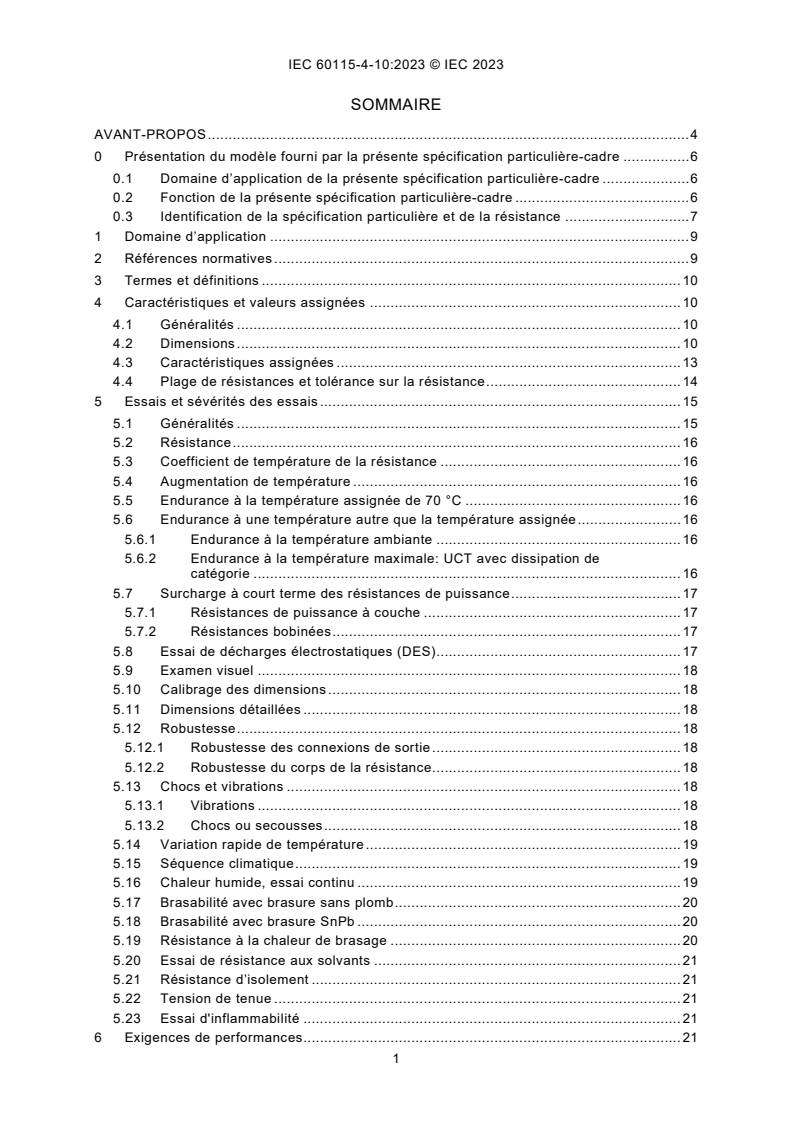
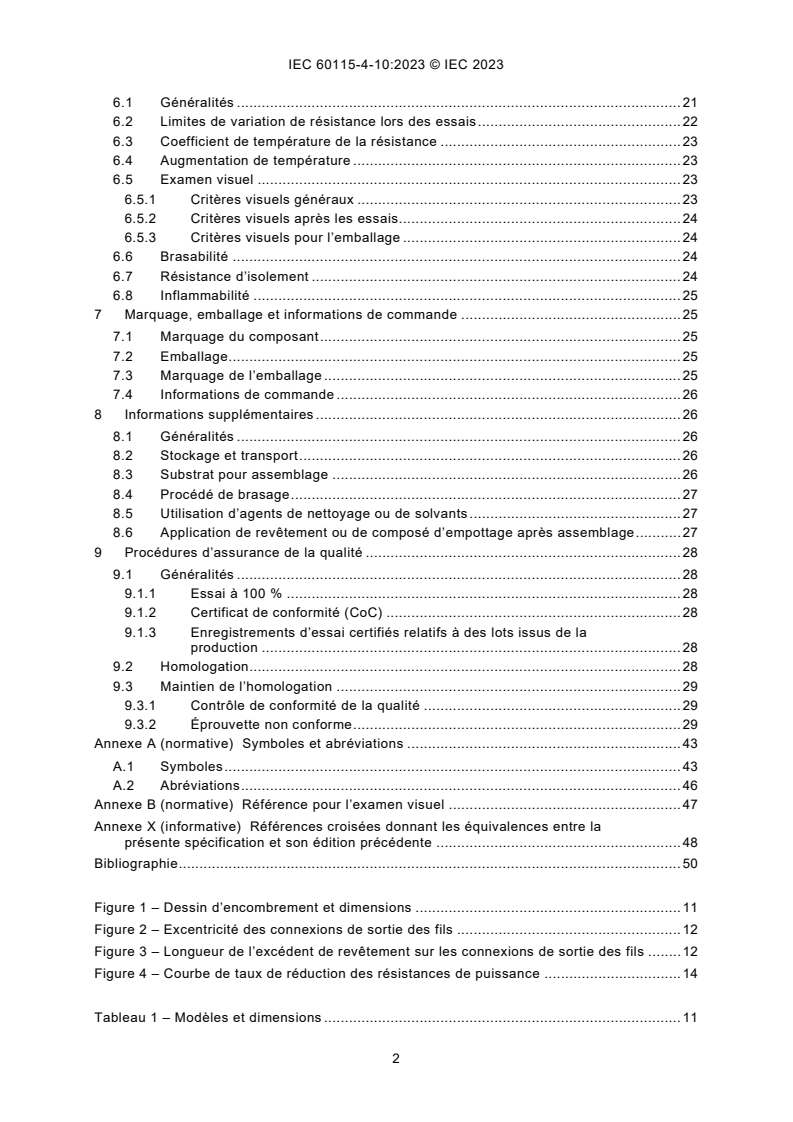
IEC 60115-4-10:2023 - Résistances fixes utilisées dans les équipements électroniques - Partie 4-10: Spécification particulière-cadre: Résistances de puissance à broches axiales pour assemblage par trous traversants sur cartes de circuit imprimé (carte THT) pour des équipements électroniques généraux, niveau de classification G
iec60115-4-10{ed1.0}en - IEC 60115-4-10:2023 - Fixed resistors for use in electronic equipment - Part 4-10: Blank detail specification: Power resistors with axial leads for through-hole assembly on circuit boards (THT), for general electronic equipment, classification level G
Overview
IEC 60115-4-10:2023 - Fixed resistors for use in electronic equipment - Part 4‑10 - is a blank detail specification (Edition 1.0, December 2023) published by the IEC. It provides a template and required content, style and layout for drafting detail specifications for fixed power resistors with axial leads intended for through‑hole assembly (THT) on circuit boards, for general electronic equipment (classification level G) as defined in IEC 60115‑1:2020. This document is supplementary to the sectional specification and is intended for use when creating product‑specific detail specifications.
Key topics and requirements
The standard addresses the minimum contents and technical topics that detail specifications must include. Major sections covered are:
- Identification and scope - template use, resistor identification and intended application (classification level G).
- Characteristics and ratings - dimensions, electrical ratings, resistance ranges and tolerances, temperature coefficient, and derating guidance.
- Tests and test severities - a comprehensive test programme including resistance measurement, temperature coefficient, temperature rise, endurance (including endurance at 70 °C and other specified temperatures), short‑term overload, ESD, shock and vibration, rapid temperature change, climatic and damp‑heat tests, solderability (lead‑free and SnPb), resistance to soldering heat, solvent resistance, insulation resistance, voltage proof and flammability.
- Performance requirements - limits for change of resistance after tests, permitted temperature‑related resistance variation, temperature rise limits, visual criteria and solderability/pass/fail limits.
- Marking, packaging and ordering information - required data for components and packaging.
- Quality assessment procedures - 100% testing, certificates of conformity, qualification approval, maintenance and lot release testing.
Figures and tables in the document provide outline dimensions, derating curves, climatic categories and test schedules to support consistent specification drafting.
Practical applications and users
IEC 60115‑4‑10 is useful for:
- Resistor manufacturers preparing product detail specifications and datasheets for axial lead power resistors (THT).
- Component engineers and purchasers who need consistent procurement specifications and acceptance criteria.
- Test laboratories and quality teams designing test programs that align with IEC requirements.
- Design engineers specifying through‑hole power resistors for general electronic equipment to ensure reliability and compliance.
Keywords: IEC 60115-4-10, fixed power resistors, axial leads, THT, through‑hole resistors, classification level G, detail specification, resistor testing, solderability, temperature coefficient.
Related standards
- IEC 60115‑1:2020 - general terms, definitions and classification (classification level G referenced).
- Other parts of the IEC 60115 series (sectional and detail specifications) that apply to different resistor styles or application classes.
Buy Documents
IEC 60115-4-10:2023 - Fixed resistors for use in electronic equipment - Part 4-10: Blank detail specification: Power resistors with axial leads for through-hole assembly on circuit boards (THT), for general electronic equipment, classification level G Released:12/15/2023
IEC 60115-4-10:2023 - Résistances fixes utilisées dans les équipements électroniques - Partie 4-10: Spécification particulière-cadre: Résistances de puissance à broches axiales pour assemblage par trous traversants sur cartes de circuit imprimé (carte THT) pour des équipements électroniques généraux, niveau de classification G
iec60115-4-10{ed1.0}en - IEC 60115-4-10:2023 - Fixed resistors for use in electronic equipment - Part 4-10: Blank detail specification: Power resistors with axial leads for through-hole assembly on circuit boards (THT), for general electronic equipment, classification level G
Frequently Asked Questions
IEC 60115-4-10:2023 is a standard published by the International Electrotechnical Commission (IEC). Its full title is "Fixed resistors for use in electronic equipment - Part 4-10: Blank detail specification: Power resistors with axial leads for through-hole assembly on circuit boards (THT), for general electronic equipment, classification level G". This standard covers: IEC 60115-4-10:2023 is applicable to the drafting of detail specifications for fixed power resistors with leads, classified to level G, which is defined in IEC 60115‑1:2020, 3.4 for general electronic equipment. It is a supplementary document to the sectional specification and contains requirements for style, layout and minimum contents of detail specifications.
IEC 60115-4-10:2023 is applicable to the drafting of detail specifications for fixed power resistors with leads, classified to level G, which is defined in IEC 60115‑1:2020, 3.4 for general electronic equipment. It is a supplementary document to the sectional specification and contains requirements for style, layout and minimum contents of detail specifications.
IEC 60115-4-10:2023 is classified under the following ICS (International Classification for Standards) categories: 31.040.10 - Fixed resistors. The ICS classification helps identify the subject area and facilitates finding related standards.
IEC 60115-4-10:2023 is available in PDF format for immediate download after purchase. The document can be added to your cart and obtained through the secure checkout process. Digital delivery ensures instant access to the complete standard document.
Standards Content (Sample)
IEC 60115-4-10 ®
Edition 1.0 2023-12
INTERNATIONAL
STANDARD
Fixed resistors for use in electronic equipment –
Part 4-10: Blank detail specification: Power resistors with axial leads for
through-hole assembly on circuit boards (THT), for general electronic
equipment, classification level G
All rights reserved. Unless otherwise specified, no part of this publication may be reproduced or utilized in any form
or by any means, electronic or mechanical, including photocopying and microfilm, without permission in writing from
either IEC or IEC's member National Committee in the country of the requester. If you have any questions about IEC
copyright or have an enquiry about obtaining additional rights to this publication, please contact the address below or
your local IEC member National Committee for further information.
IEC Secretariat Tel.: +41 22 919 02 11
3, rue de Varembé info@iec.ch
CH-1211 Geneva 20 www.iec.ch
Switzerland
About the IEC
The International Electrotechnical Commission (IEC) is the leading global organization that prepares and publishes
International Standards for all electrical, electronic and related technologies.
About IEC publications
The technical content of IEC publications is kept under constant review by the IEC. Please make sure that you have the
latest edition, a corrigendum or an amendment might have been published.
IEC publications search - webstore.iec.ch/advsearchform IEC Products & Services Portal - products.iec.ch
The advanced search enables to find IEC publications by a Discover our powerful search engine and read freely all the
variety of criteria (reference number, text, technical publications previews. With a subscription you will always have
committee, …). It also gives information on projects, replaced access to up to date content tailored to your needs.
and withdrawn publications.
Electropedia - www.electropedia.org
IEC Just Published - webstore.iec.ch/justpublished
The world's leading online dictionary on electrotechnology,
Stay up to date on all new IEC publications. Just Published
containing more than 22 300 terminological entries in English
details all new publications released. Available online and once
and French, with equivalent terms in 19 additional languages.
a month by email.
Also known as the International Electrotechnical Vocabulary
(IEV) online.
IEC Customer Service Centre - webstore.iec.ch/csc
If you wish to give us your feedback on this publication or need
further assistance, please contact the Customer Service
Centre: sales@iec.ch.
IEC 60115-4-10 ®
Edition 1.0 2023-12
INTERNATIONAL
STANDARD
Fixed resistors for use in electronic equipment –
Part 4-10: Blank detail specification: Power resistors with axial leads for
through-hole assembly on circuit boards (THT), for general electronic
equipment, classification level G
INTERNATIONAL
ELECTROTECHNICAL
COMMISSION
ICS 31.040.10 ISBN 978-2-8322-7959-5
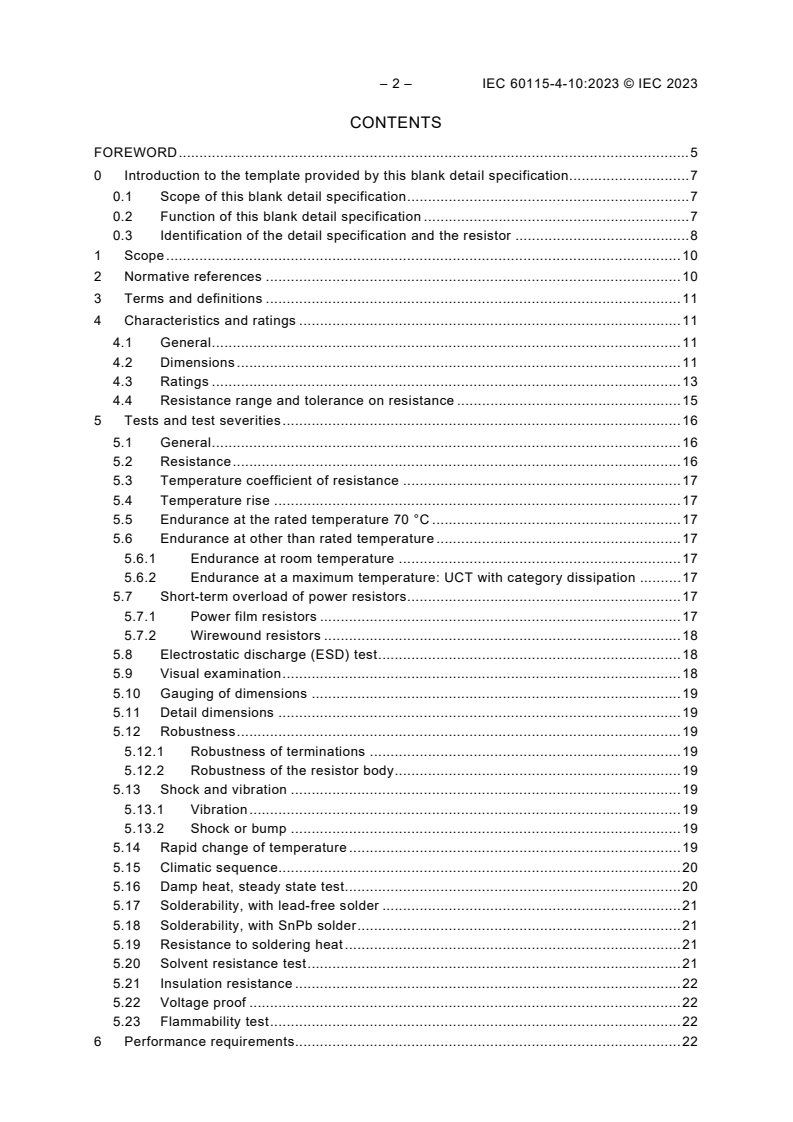
– 2 – IEC 60115-4-10:2023 © IEC 2023
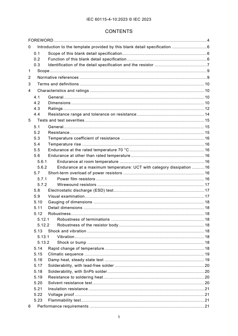
CONTENTS
FOREWORD . 5
0 Introduction to the template provided by this blank detail specification. 7
0.1 Scope of this blank detail specification . 7
0.2 Function of this blank detail specification . 7
0.3 Identification of the detail specification and the resistor . 8
1 Scope . 10
2 Normative references . 10
3 Terms and definitions . 11
4 Characteristics and ratings . 11
4.1 General . 11
4.2 Dimensions . 11
4.3 Ratings . 13
4.4 Resistance range and tolerance on resistance . 15
5 Tests and test severities . 16
5.1 General . 16
5.2 Resistance . 16
5.3 Temperature coefficient of resistance . 17
5.4 Temperature rise . 17
5.5 Endurance at the rated temperature 70 °C . 17
5.6 Endurance at other than rated temperature . 17
5.6.1 Endurance at room temperature . 17
5.6.2 Endurance at a maximum temperature: UCT with category dissipation . 17
5.7 Short-term overload of power resistors. 17
5.7.1 Power film resistors . 17
5.7.2 Wirewound resistors . 18
5.8 Electrostatic discharge (ESD) test . 18
5.9 Visual examination . 18
5.10 Gauging of dimensions . 19
5.11 Detail dimensions . 19
5.12 Robustness . 19
5.12.1 Robustness of terminations . 19
5.12.2 Robustness of the resistor body . 19
5.13 Shock and vibration . 19
5.13.1 Vibration . 19
5.13.2 Shock or bump . 19
5.14 Rapid change of temperature . 19
5.15 Climatic sequence. 20
5.16 Damp heat, steady state test. 20
5.17 Solderability, with lead-free solder . 21
5.18 Solderability, with SnPb solder . 21
5.19 Resistance to soldering heat . 21
5.20 Solvent resistance test . 21
5.21 Insulation resistance . 22
5.22 Voltage proof . 22
5.23 Flammability test . 22
6 Performance requirements. 22
6.1 General . 22
6.2 Limits for change of resistance at tests . 22
6.3 Temperature coefficient of resistance . 23
6.4 Temperature rise . 24
6.5 Visual examination . 24
6.5.1 General visual criteria . 24
6.5.2 Visual criteria after tests . 25
6.5.3 Visual criteria for packaging . 25
6.6 Solderability . 25
6.7 Insulation resistance . 25
6.8 Flammability . 26
7 Marking, packaging and ordering information . 26
7.1 Marking of the component . 26
7.2 Packaging . 26
7.3 Marking of the packaging . 26
7.4 Ordering information . 26
8 Additional information . 27
8.1 General . 27
8.2 Storage and Transportation . 27
8.3 Substrate for assembly . 27
8.4 Soldering process . 27
8.5 Use of cleaning agents or solvents . 27
8.6 Coating or potting after assembly . 28
9 Quality assessment procedures . 28
9.1 General . 28
9.1.1 100 % test . 28
9.1.2 Certificate of Conformity (CoC) . 28
9.1.3 Certified test records of released lots . 29
9.2 Qualification approval . 29
9.3 Maintenance of a qualification approval . 29
9.3.1 Quality conformance inspection . 29
9.3.2 Non-conforming specimen . 29
Annex A (normative) Symbols and abbreviated terms . 41
A.1 Symbols . 41
A.2 Abbreviated terms . 43
Annex B (normative) Reference for visual examination . 44
Annex X (informative) Cross-reference for references to the prior revision of this
specification. 45
Bibliography . 46
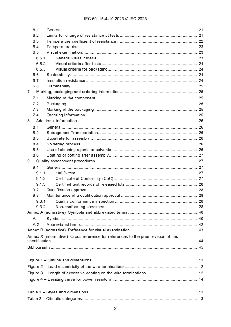
Figure 1 – Outline and dimensions . 12
Figure 2 – Lead eccentricity of the wire terminations . 13
Figure 3 – Length of excessive coating on the wire terminations . 13
Figure 4 – Derating curve for power resistors . 15
Table 1 – Styles and dimensions. 12
Table 2 – Climatic categories . 14
– 4 – IEC 60115-4-10:2023 © IEC 2023
Table 3 – Ratings. 14
Table 4 – Temperature coefficients, tolerances and resistance ranges for climatic
category . / . / . . 16
Table 5 – Short-term overload duration . 18
Table 6 – ESD test voltages . 18
Table 7 – Additional cycles of the damp heat, cyclic test . 20
Table 8 – Damp heat, steady state test duration . 20
Table 9 – Limits for change of resistance at tests . 23
Table 10 – Permitted change of resistance due to the variation of temperature . 24
Table 11 – Test schedule for the qualification approval of power resistors . 30
Table 12 – Test schedule for quality conformance inspection of power resistors . 35
Table X.1 – Cross reference for references to clauses . 45
INTERNATIONAL ELECTROTECHNICAL COMMISSION
____________
FIXED RESISTORS FOR USE IN ELECTRONIC EQUIPMENT –
Part 4-10: Blank detail specification:
Power resistors with axial leads
for through-hole assembly on circuit boards (THT),
for general electronic equipment, classification level G
FOREWORD
1) The International Electrotechnical Commission (IEC) is a worldwide organization for standardization comprising
all national electrotechnical committees (IEC National Committees). The object of IEC is to promote international
co-operation on all questions concerning standardization in the electrical and electronic fields. To this end and
in addition to other activities, IEC publishes International Standards, Technical Specifications, Technical Reports,
Publicly Available Specifications (PAS) and Guides (hereafter referred to as "IEC Publication(s)"). Their
preparation is entrusted to technical committees; any IEC National Committee interested in the subject dealt with
may participate in this preparatory work. International, governmental and non-governmental organizations liaising
with the IEC also participate in this preparation. IEC collaborates closely with the International Organization for
Standardization (ISO) in accordance with conditions determined by agreement between the two organizations.
2) The formal decisions or agreements of IEC on technical matters express, as nearly as possible, an international
consensus of opinion on the relevant subjects since each technical committee has representation from all
interested IEC National Committees.
3) IEC Publications have the form of recommendations for international use and are accepted by IEC National
Committees in that sense. While all reasonable efforts are made to ensure that the technical content of IEC
Publications is accurate, IEC cannot be held responsible for the way in which they are used or for any
misinterpretation by any end user.
4) In order to promote international uniformity, IEC National Committees undertake to apply IEC Publications
transparently to the maximum extent possible in their national and regional publications. Any divergence between
any IEC Publication and the corresponding national or regional publication shall be clearly indicated in the latter.
5) IEC itself does not provide any attestation of conformity. Independent certification bodies provide conformity
assessment services and, in some areas, access to IEC marks of conformity. IEC is not responsible for any
services carried out by independent certification bodies.
6) All users should ensure that they have the latest edition of this publication.
7) No liability shall attach to IEC or its directors, employees, servants or agents including individual experts and
members of its technical committees and IEC National Committees for any personal injury, property damage or
other damage of any nature whatsoever, whether direct or indirect, or for costs (including legal fees) and
expenses arising out of the publication, use of, or reliance upon, this IEC Publication or any other IEC
Publications.
8) Attention is drawn to the Normative references cited in this publication. Use of the referenced publications is
indispensable for the correct application of this publication.
9) IEC draws attention to the possibility that the implementation of this document may involve the use of (a)
patent(s). IEC takes no position concerning the evidence, validity or applicability of any claimed patent rights in
respect thereof. As of the date of publication of this document, IEC had not received notice of (a) patent(s), which
may be required to implement this document. However, implementers are cautioned that this may not represent
the latest information, which may be obtained from the patent database available at https://patents.iec.ch or
www.iso.org/patents. IEC shall not be held responsible for identifying any or all such patent rights.
IEC 60115-4-10 has been prepared by IEC technical committee 40: Capacitors and resistors
for electronic equipment. It is an International Standard.
This first edition cancels and replaces IEC 60115-4-1:1983. This edition constitutes a technical
revision.
This edition includes the following significant technical changes with respect to the previous
edition:
a) it employs the product classification based on application requirements as defined in the
generic specification IEC 60115-1:2020;
– 6 – IEC 60115-4-10:2023 © IEC 2023
b) it permits the specification additional dimensional requirements concerning the eccentricity
of termination wires and the coating extending onto wires;
c) it provides for a tabulated presentation of resistance ranges in relationship to the
temperature coefficient and the tolerance;
d) it supports solderability testing for both, traditional lead-bearing soldering and up-to-date
lead-free soldering, as required;
e) it introduces a test for the specimens’ robustness to electrostatic discharge if required;
f) it introduces a test for the specimens’ resistance to solvents if required;
g) it introduces a test for the flammability of the specimens if required;
h) it employs consistent stability requirements grouped in stability classes;
i) it supports the provision of detailed visual acceptance criteria
j) it includes the requirement for a visual inspection of the primary and proximity packaging;
k) it provides the correlated test schedules for a qualification approval and for subsequent
quality conformance inspections side by side;
l) it employs quality assessment procedures which meet the requirements of a zero-defect
approach, which evades the use of historic AQL levels and the permission of non-conforming
specimens in test groups;
m) it provides for the inclusion of specific visual acceptance criteria, to be applied in addition
to those given in Annex B of the sectional specification IEC 60115-4:2022;
n) furthermore, it employs a new document structure, for which a transition guidance is
provided in Annex X.
The text of this International Standard is based on the following documents:
Draft Report on voting
40/3039/CDV 40/3078/RVC
Full information on the voting for its approval can be found in the report on voting indicated in
the above table.
The language used for the development of this International Standard is English.
A list of all parts in the IEC 60115 series, published under the general title Fixed resistors for
use in electronic equipment, can be found on the IEC website.
This document was drafted in accordance with ISO/IEC Directives, Part 2, and developed in
accordance with ISO/IEC Directives, Part 1 and ISO/IEC Directives, IEC Supplement, available
at www.iec.ch/members_experts/refdocs. The main document types developed by IEC are
described in greater detail at www.iec.ch/publications.
The committee has decided that the contents of this document will remain unchanged until the
stability date indicated on the IEC website under webstore.iec.ch in the data related to the
specific document. At this date, the document will be
• reconfirmed,
• withdrawn, or
• revised.
0 Introduction to the template provided by this blank detail specification
COMMENT This introduction is not intended to be copied into the drafted detail specification. Therefore, it is
positioned in front of the conventional document structure and clause numbering range. It nevertheless contains
normative requirements to the drafted detail specification.
0.1 Scope of this blank detail specification
This part of IEC 60115-4 is applicable to the drafting of detail specifications for fixed power
resistors with leads, classified to level G, which is defined in IEC 60115-1:2020, 3.4 for general
electronic equipment.
Another part of IEC 60115-4 provides separate blank detail specifications for the drafting of
detail specifications for fixed power resistors with leads, classified to level P and/or to level R.
Yet other parts of IEC 60115-4 may be issued to provide blank detail specifications for the
drafting of detail specifications for vertical or radial fixed power resistors of other technologies
or of other classification levels.
0.2 Function of this blank detail specification
A blank detail specification is a supplementary document to the sectional specification and
contains requirements for style, layout and minimum contents of detail specifications. Detail
specifications not complying with these requirements shall not be accepted as being in
accordance with IEC specifications nor shall they be described as such.
Detail specifications complying with the requirements of this blank detail specification are a
legitimate basis for the quality assessment of leaded fixed power resistors under an adequate
quality assessment system, e.g. the IEC Quality Assessment System for Electronic Components
(IECQ System), whereas the plain blank detail specification is not a suitable basis.
The detail specification should contain a table of contents prior to the first page of the actual
specification.
In the preparation of the detail specification, the content of IEC 60115-4:2022, 8.2 shall be
taken into account. The detail specification should be written by using the preferred values
given in IEC 60115-4.
Units, graphical symbols and letter symbols shall, whenever possible, be taken from those
specified by the following standards:
– IEC 60027-1, Letter symbols to be used in electrical technology – Part 1: General
– IEC 60617, Graphical symbols for diagrams
– IEC 80000 (all parts), Quantities and units
– ISO 80000 (all parts), Quantities and units
This blank detail specification uses for its purpose two different kinds of notes:
NOTE For notes which give additional information intended to assist the understanding or use of the resulting
document and therefore shall be copied as NOTE into the drafted detail specification. As outlined in the ISO/IEC
directives, these notes shall not contain any requirement, instruction, recommendation or permission.
COMMENT For editorial notes which are intended to aid and direct the specification writer and therefore shall
not be copied into the drafted detail specification. In order to accomplish their function, editorial notes require
the use of instructions, recommendations and permissions addressed to the writer of the detail specification.
– 8 – IEC 60115-4-10:2023 © IEC 2023
0.3 Identification of the detail specification and the resistor
The first page of the detail specification should have a layout starting with a title block as
recommended on the following page.
The numbers in square brackets are editorial references, which are not intended to be copied
into the drafted detail specification, and which correspond to the following information on the
contents which shall be inserted in the indicated positions.
[1] The name of the standardization organization under whose authority the detail
specification is published and, if applicable, the organization from whom the detail
specification is available.
[2] The number allocated to the detail specification by the IEC or by the responsible
standardization organization, together with the date of issue and issue number, as
applicable. Further reference details required by the responsible standardization
organization or quality assessment system may be given here, including an established
mark of conformity, as applicable.
[3] The number and issue date and number, as applicable, of the relevant generic
specification, sectional specification and blank detail specification, where the referenced
issues shall be the most recent issues of the respective specifications.
[4] The title of the detail specification, providing a short description of the type of resistors.
This entry should support the discrimination between similar specifications and should
be suitable for an entry in a register of approvals or in a catalogue of standards. It may
duplicate information given in fields [6] and [7] and in the textual scope in Clause 1.
[5] An outline drawing or illustration of the products.
This entry should aid the easy recognition of the specified resistors and, if possible,
support the discrimination between similar specifications. It may duplicate information
given in Figure 1.
[6] Information on the typical construction of the resistors (where applicable), information of
the specified resistors being insulated or non-insulated (see IEC 60115-1:2020, 3.1.7),
and information on compatibility with a specific soldering process (if applicable, see 8.3).
This entry may duplicate information given in the textual scope in Clause 1.
[7] The classification level of the resistors covered by this detail specification, the level of
quality assessment (Assessment level EZ), and the general level of stability
requirements at performance tests (Stability class).
This information may duplicate information given in the textual scope in Clause 1.
[8] Optional field for table notes.
[9] Statement(s) about the availability of information on components qualified to this detail
specification, if applied within a full quality assessment system.
Example for the use within the IECQ system:
Information about components qualified to this detail specification is available in the
approvals section of the website http://www.iecq.org.
Specification available from: IEC 60115-4-10XX: 20YY
[1] [2]
Electronic components of assessed quality in accordance with:
Generic Specification: IEC 60115-1:2020
Sectional Specification: IEC 60115-4:2022
Blanc Detail Specification: IEC 60115-4-10:2023
[3]
FIXED RESISTORS FOR USE IN ELECTRONIC EQUIPMENT –
Part 4-10XX: Detail specification:
Power resistors with axial leads for through-hole assembly on circuit boards (THT), for general electronic
equipment – classification level G
[4]
Technology info
[5]
Insulated / non-insulated [6]
Outline drawing
Product classification level G
Assessment level EZ [7]
Stability classes .
[8]
COMMENT The remainder of this page is intentionally left empty in order to start Clause 1 on top of the next page.
Information about components qualified to this detail specification is available ….
[9]
– 10 – IEC 60115-4-10:2023 © IEC 2023
FIXED RESISTORS FOR USE IN ELECTRONIC EQUIPMENT –
Part 4-10: Blank detail specification:
Power resistors with axial leads
for through-hole assembly on circuit boards (THT),
for general electronic equipment, classification level G
1 Scope
COMMENT The text of this clause may repeat information already given in some fields of the above title block.
Essential information on the special type of components covered by the drafted detail specification may be added,
preferably at the place marked with "…".
This detail specification specifies the characteristics and ratings of fixed power resistors with
axial leads for through hole assembly (THT) on circuit boards …
...
The resistors covered herein are classified to level G, as defined in IEC 60115-1:2020, 3.4 for
general electronic equipment, typically operated under benign or moderate environmental
conditions, where the major requirement is function. Examples for level G include consumer
products and telecommunication user terminals.
This detail specification is based upon the blank detail specification IEC 60115-4-10:2023.
This detail specification establishes test schedules and performance requirements permitting
the quality assessment of the resistors covered herein according to the quality assessment
procedures specified by IEC 60115-1:2020, Annex Q.
2 Normative references
The following documents are referred to in the text in such a way that some or all of their content
constitutes requirements of this document. For dated references, only the edition cited applies.
For undated references, the latest edition of the referenced document (including any
amendments) applies.
IEC 60062, Marking codes for resistors and capacitors
IEC 60063, Preferred number series for resistors and capacitors
IEC 60115-1:2020, Fixed resistors for use in electronic equipment – Part 1: Generic
specification
IEC 60115-4:2022, Fixed resistors for use in electronic equipment – Part 4: Sectional
specification: Power resistors for through hole assembly on circuit boards (THT) or for assembly
on chassis
specification: Power resistors with axial leads for through-hole assembly on circuit boards (THT),
for general electronic equipment, classification level G
IEC 60286-1, Packaging of components for automatic handling – Part 1: Tape packaging of
components with axial leads on continuous tapes
IEC 60294, Measurement of the dimensions of a cylindrical component with axial terminations
IEC 60301, Preferred diameters of wire terminations of capacitors and resistors
IEC 61760-1, Surface mounting technology – Part 1: Standard method for the specification of
surface mounting components (SMDs)
IEC 61193-2:2007, Quality assessment systems – Part 2: Selection and use of sampling plans
for inspection of electronic components and packages
…
COMMENT 1 The above list of normative references provides an example and needs to be adapted to the actual
requirements of the drafted detail specification, indicated by the space marked with "…", which however does not
preclude from sorting in proper numerical order.
COMMENT 2 According to the ISO/IEC directives, dated references are required when reference is made to a
specific part of the referenced standard and generally should be applied only in such cases.
COMMENT 3 It is recommended to update any dated references to the most recent revision of the referenced
standard when drafting a detail specification. This involves updating of the dated normative references within the
text of the drafted detail specification.
3 Terms and definitions
For the purposes of this document, the terms and definitions given in IEC 60115-1 and in
IEC 60115-4, as well as the following, apply.
…
COMMENT Any terms and their respective definitions specifically required for the scope of the drafted detail
specification may be inserted in the space marked with "…", using the specified numbering and format. Otherwise,
the above statement should be reduced to "For the purposes of this document, the terms and definitions given in
IEC 60115-1 and in IEC 60115-4 apply." if no further terms or definitions are required in the drafted detail
specification.
ISO and IEC maintain terminology databases for use in standardization at the following
addresses:
• IEC Electropedia: available at https://www.electropedia.org/
• ISO Online browsing platform: available at https://www.iso.org/obp
4 Characteristics and ratings
4.1 General
Various parameters of this component are precisely defined in this specification. Unspecified
parameters can vary from one component to another.
4.2 Dimensions
The shape and dimensions of the resistors covered by this specification are shown in Figure 1,
with the specific styles and their respective dimensions given in Table 1. Other shapes are
permissible within the given dimensions.
– 12 – IEC 60115-4-10:2023 © IEC 2023
Figure 1 – Outline and dimensions
COMMENT 1 See IEC 60115-4:2022, 8.2.1.
COMMENT 2 The details shown in Figure 1 may repeat information already given in some fields of the title block
above. Figure 1 in particular needs to define all dimensions intended to be verified by measurements, which generally
includes those dimensions to be specified in Table 1.
Table 1 – Styles and dimensions
g f
Style Dimensions Mass
b c d e
a
D L d l m
Metric X Y
min
mm mm mm mm mg
a
Historical style code, for information only.
b
the body diameter of the resistor D shall be gauged as specified in IEC 60294, see IEC 60115-4:2022 5.3.11.
c
the body length of the resistor L shall be gauged and measured according to IEC 60294, see
IEC 60115-4:2022, 5.3.11 and 5.3.12 respectively.
d
Nominal diameter of the lead-wires d, with permissible tolerances according to IEC 60301.
e
the minimum lead length l for products in tape packaging according to IEC 60286-1 applies to the length of
min
the free sections of lead-wire between the resistor body and each tape. For untapped resistors it applies to
the length of each lead-wire.
f
for information only.
g.
For products which have their origin in the imperial system of units, the inch dimensions can be given
additionally for information, presented in square brackets.
COMMENT 3 See IEC 60115-4, 2022, 8.2.2.
COMMENT 4 The metric style designation is the normative designation used in all other places throughout this
detail specification, see IEC 60115-4:2022, 4.2.1.1. Column X is an optional column for additional style information,
e.g. for traditional alphabetic designations, which generally need to be marked with a respective footnote, e.g. as
"Historical style code, for information only".
COMMENT 5 The dimensions for body diameter D, body length L, lead-wire diameter d and minimum free lead
length l are given as example based on the requirements for axial leaded resistors with cylindrical body and need
min
to correspond to the dimensions identified in Figure 1. The choice of specified dimensions needs to be adapted to
the actual requirements of the drafted detail specification and the shape of products covered therein. The dimensions
may be given in the format of nominal values plus tolerance, or by stating permissible minimum and maximum values.
Columns for additional dimensions may be inserted as required.
COMMENT 6 Column Y represents one or more optional column(s) for the prescription of an additional dimension,
e.g. the permissible lead eccentricity and/or the permissible length of excessive coating on the leads, as required.
COMMENT 7 The specified minimum lead length should consider the variety of inside tape spacing specified as
dimension B by IEC 60286-1, plus the permissible window for the lateral resistor body location, given there as
dimension K.
COMMENT 8 The component mass is not intended to be verified by an inspection procedure. It should be given as
the maximum mass of a single component and should be marked with a respective footnote as "For information only".
The wire terminations of the resistor shall emerge concentrically from the end faces of the
resistor body, see IEC 60115-4:2022, 4.2.1.4 with IEC 60115-4:2022, Figure 9. The real
eccentricity e, as shown in Figure 2, shall not exceed the limit given in Table 1. For gauging of
the lead eccentricity, the effective eccentricity e’ should be used, see IEC 60115-4:2022, 4.2.1.4.
Figure 2 – Lead eccentricity of the wire terminations
COMMENT 9 The above paragraph and figure are optional and given as an example for the specification of a
permissible lead eccentricity. If this specification is used in the drafted detail specification, a suitable method for
gauging and/or measuring of the lead eccentricity needs to be described, e.g. in the respective subclauses of
Clause 5. Alternatively, the deletion of this paragraph and figure will result in the need to update the numbering of
subsequent figures accordingly.
The resistor shall be properly coated in order to provide a suitable protection against
mechanical, electrical and climatic influences, e.g. by means of a conformal lacquer coating. It
is typical for such coating to also cover the end faces of the resistor body, which can lead for
some amount of excessive coating to spread onto the leads, see IEC 60115-4:2022, 4.2.1.2
and Figure 7. The length of excessive coating c, as shown in Figure 3, shall not exceed the limit
given in Table 1.
Figure 3 – Length of excessive coating on the wire terminations
COMMENT 10 The above paragraph and figure are optional and given as an example for the specification of a
permissible length of excessive coating on the wire terminations. If this specification is used in the drafted detail
specification, a suitable method for gauging and/or measuring of the length of excessive coating needs to be
described, e.g. in the respective subclauses of Clause 5. Alternatively, the deletion of this paragraph and figure will
result in the need to update the numbering of subsequent figures accordingly.
4.3 Ratings
The climatic categories applied in this detail specification are given in Table 2.
– 14 – IEC 60115-4-10:2023 © IEC 2023
Table 2 – Climatic categories
Climatic category
LCT / UCT / duration
... / ... / ...
... / ... / ...
COMMENT 1 See IEC 60115-4:2022, 8.2.3. and 4.3.
COMMENT 2 Table 2 may be amended with a column showing the key parameter to which different climatic
categories are allocated in the purpose of discrimination, e.g. the applied stability classes.
The upper category temperature (UCT), which is used for test procedures, should be lower than
the maximum element temperature (MET).
Table 3 – Ratings
Limiting element
Rated Insulation voltage
Style X voltage
dissipation DC or AC peak
DC or AC RMS
P U U
70 max ins
W V V
NOTE For insulated resistors, the insulation voltage U is verified with a test duration of one minute. However,
ins
long time insulation properties can be affected by the influence of moisture, organic material and electrical field
across the insulating layer(s). For non-insulated resistors, this is the max voltage against ambient.
COMMENT 3 See IEC 60115-4:2022, 8.2.6, 8.2.7 and 8.2.8.
COMMENT 4 Column X is an optional column for additional information, e.g. an additional rated dissipation at
another ambient temperature than the rated temperature 70 °C. Such information should however only be presented,
if it is a traditionally well-established information.
COMMENT 5 The insulation voltage shall not be specified lower than the peak value of the AC voltage that can be
applied continuously to the resistors and therefore shall not be rated less than U = 1,42 × U . The insulation
ins max
voltage is not an applicable rating for non-insulated resistors, therefore the entry in this column shall be "n/a" and
the note of Table 3 shall be omitted in detail specifications drafted for non-insulated resistors.
COMMENT 6 Different sets of ratings may be assigned to variations of another parameter, e.g. climatic categories
or stability classes. Then such different sets of ratings should be given in separate tables which need to be clearly
assigned to the relevant parameter(s). According to the ISO/IEC directives, such duplicate tables need to be titled
with subsequent numbers as required, which will result in the need to update the numbering of subsequent tables
accordingly.
The permissible dissipation of resistors covered by this detail specification is the rated
dissipation as given in Table 3, which is derated for an ambient temperature above the rated
temperature 70 °C according to the diagram in Figure 4.
Figure 4 – Derating curve for power resistors
COMMENT 7 See IEC 60115-4:2022, 8.2.6.
COMMENT 8 The scale of derated dissipation may be given as absolute value in Watt or relative in percent as a
fraction of the rated dissipation P .
COMMENT 9 A larger area of operation or permissible temperature rise may be given by the detail specification,
provided it includes all the area given in Figure 4.
4.4 Resistance range and tolerance on resistance
Table 4 gives the combinations of temperature coefficient, tolerance on resistance and
resistance range which can be approved in climatic category . / . / . according to this detail
specification.
COMMENT 1 The above paragraph needs to be adapted
...
IEC 60115-4-10 ®
Edition 1.0 2023-12
NORME
INTERNATIONALE
Résistances fixes utilisées dans les équipements électroniques -
Partie 4-10: Spécification particulière-cadre: Résistances de puissance à
broches axiales pour assemblage par trous traversants sur cartes de circuit
imprimé (carte THT) pour des équipements électroniques généraux, niveau de
classification G
ICS 31.040.10 ISBN 978-2-8327-1518-5
Droits de reproduction réservés. Sauf indication contraire, aucune partie de cette publication ne peut être reproduite ni
utilisée sous quelque forme que ce soit et par aucun procédé, électronique ou mécanique, y compris la photocopie et
les microfilms, sans l'accord écrit de l'IEC ou du Comité national de l'IEC du pays du demandeur. Si vous avez des
questions sur le copyright de l'IEC ou si vous désirez obtenir des droits supplémentaires sur cette publication, utilisez
les coordonnées ci-après ou contactez le Comité national de l'IEC de votre pays de résidence.
IEC Secretariat Tel.: +41 22 919 02 11
3, rue de Varembé info@iec.ch
CH-1211 Geneva 20 www.iec.ch
Switzerland
A propos de l'IEC
La Commission Electrotechnique Internationale (IEC) est la première organisation mondiale qui élabore et publie des
Normes internationales pour tout ce qui a trait à l'électricité, à l'électronique et aux technologies apparentées.
A propos des publications IEC
Le contenu technique des publications IEC est constamment revu. Veuillez vous assurer que vous possédez l’édition la
plus récente, un corrigendum ou amendement peut avoir été publié.
Recherche de publications IEC - IEC Products & Services Portal - products.iec.ch
webstore.iec.ch/advsearchform Découvrez notre puissant moteur de recherche et consultez
La recherche avancée permet de trouver des publications gratuitement tous les aperçus des publications, symboles
IEC en utilisant différents critères (numéro de référence, graphiques et le glossaire. Avec un abonnement, vous aurez
texte, comité d’études, …). Elle donne aussi des toujours accès à un contenu à jour adapté à vos besoins.
informations sur les projets et les publications remplacées
ou retirées. Electropedia - www.electropedia.org
Le premier dictionnaire d'électrotechnologie en ligne au
IEC Just Published - webstore.iec.ch/justpublished monde, avec plus de 22 500 articles terminologiques en
Restez informé sur les nouvelles publications IEC. Just anglais et en français, ainsi que les termes équivalents
dans 25 langues additionnelles. Egalement appelé
Published détaille les nouvelles publications parues.
Disponible en ligne et une fois par mois par email. Vocabulaire Electrotechnique International (IEV) en ligne.
Service Clients - webstore.iec.ch/csc
Si vous désirez nous donner des commentaires sur cette
publication ou si vous avez des questions contactez-
nous: sales@iec.ch.
SOMMAIRE
AVANT-PROPOS . 4
0 Présentation du modèle fourni par la présente spécification particulière-cadre . 6
0.1 Domaine d’application de la présente spécification particulière-cadre . 6
0.2 Fonction de la présente spécification particulière-cadre . 6
0.3 Identification de la spécification particulière et de la résistance . 7
1 Domaine d’application . 9
2 Références normatives . 9
3 Termes et définitions . 10
4 Caractéristiques et valeurs assignées . 10
4.1 Généralités . 10
4.2 Dimensions . 10
4.3 Caractéristiques assignées . 13
4.4 Plage de résistances et tolérance sur la résistance . 14
5 Essais et sévérités des essais . 15
5.1 Généralités . 15
5.2 Résistance . 16
5.3 Coefficient de température de la résistance . 16
5.4 Augmentation de température . 16
5.5 Endurance à la température assignée de 70 °C . 16
5.6 Endurance à une température autre que la température assignée . 16
5.6.1 Endurance à la température ambiante . 16
5.6.2 Endurance à la température maximale: UCT avec dissipation de
catégorie . 16
5.7 Surcharge à court terme des résistances de puissance . 17
5.7.1 Résistances de puissance à couche . 17
5.7.2 Résistances bobinées . 17
5.8 Essai de décharges électrostatiques (DES). 17
5.9 Examen visuel . 18
5.10 Calibrage des dimensions . 18
5.11 Dimensions détaillées . 18
5.12 Robustesse . 18
5.12.1 Robustesse des connexions de sortie . 18
5.12.2 Robustesse du corps de la résistance . 18
5.13 Chocs et vibrations . 18
5.13.1 Vibrations . 18
5.13.2 Chocs ou secousses . 18
5.14 Variation rapide de température . 19
5.15 Séquence climatique . 19
5.16 Chaleur humide, essai continu . 19
5.17 Brasabilité avec brasure sans plomb . 20
5.18 Brasabilité avec brasure SnPb . 20
5.19 Résistance à la chaleur de brasage . 20
5.20 Essai de résistance aux solvants . 21
5.21 Résistance d’isolement . 21
5.22 Tension de tenue . 21
5.23 Essai d'inflammabilité . 21
6 Exigences de performances . 21
6.1 Généralités . 21
6.2 Limites de variation de résistance lors des essais . 22
6.3 Coefficient de température de la résistance . 23
6.4 Augmentation de température . 23
6.5 Examen visuel . 23
6.5.1 Critères visuels généraux . 23
6.5.2 Critères visuels après les essais . 24
6.5.3 Critères visuels pour l’emballage . 24
6.6 Brasabilité . 24
6.7 Résistance d’isolement . 24
6.8 Inflammabilité . 25
7 Marquage, emballage et informations de commande . 25
7.1 Marquage du composant . 25
7.2 Emballage . 25
7.3 Marquage de l’emballage . 25
7.4 Informations de commande . 26
8 Informations supplémentaires . 26
8.1 Généralités . 26
8.2 Stockage et transport . 26
8.3 Substrat pour assemblage . 26
8.4 Procédé de brasage . 27
8.5 Utilisation d’agents de nettoyage ou de solvants . 27
8.6 Application de revêtement ou de composé d’empottage après assemblage . 27
9 Procédures d’assurance de la qualité . 28
9.1 Généralités . 28
9.1.1 Essai à 100 % . 28
9.1.2 Certificat de conformité (CoC) . 28
9.1.3 Enregistrements d’essai certifiés relatifs à des lots issus de la
production . 28
9.2 Homologation . 28
9.3 Maintien de l’homologation . 29
9.3.1 Contrôle de conformité de la qualité . 29
9.3.2 Éprouvette non conforme . 29
Annexe A (normative) Symboles et abréviations . 43
A.1 Symboles . 43
A.2 Abréviations . 46
Annexe B (normative) Référence pour l’examen visuel . 47
Annexe X (informative) Références croisées donnant les équivalences entre la
présente spécification et son édition précédente . 48
Bibliographie . 50
Figure 1 – Dessin d’encombrement et dimensions . 11
Figure 2 – Excentricité des connexions de sortie des fils . 12
Figure 3 – Longueur de l’excédent de revêtement sur les connexions de sortie des fils . 12
Figure 4 – Courbe de taux de réduction des résistances de puissance . 14
Tableau 1 – Modèles et dimensions . 11
Tableau 2 – Catégories climatiques . 13
Tableau 3 – Valeurs assignées . 13
Tableau 4 – Coefficients de température, tolérances et plages de résistance pour la
catégorie climatique././. 15
Tableau 5 – Durée de surcharge à court terme . 17
Tableau 6 – Tensions d’essai DES. 17
Tableau 7 – Cycles supplémentaires de l’essai cyclique de chaleur humide . 19
Tableau 8 – Durée de l’essai continu de chaleur humide . 20
Tableau 9 – Limites de variation de résistance lors des essais . 22
Tableau 10 – Variation autorisée de résistance due à la variation de température . 23
Tableau 11 – Programme d’essais pour l’homologation des résistances de puissance
(1 sur 5) . 29
Tableau 12 – Programme d’essais pour le contrôle de conformité de la qualité des
résistances de puissance (1 sur 5) . 36
Tableau X.1 – Références croisées des articles . 48
COMMISSION ÉLECTROTECHNIQUE INTERNATIONALE
____________
Résistances fixes utilisées dans les équipements électroniques -
Partie 4-10: Spécification particulière-cadre:
Résistances de puissance à broches axiales pour assemblage par trous
traversants sur cartes de circuit imprimé (carte THT) pour des
équipements électroniques généraux, niveau de classification G
AVANT-PROPOS
1) La Commission Électrotechnique Internationale (IEC) est une organisation mondiale de normalisation composée
de l’ensemble des comités électrotechniques nationaux (Comités nationaux de l’IEC). L’IEC a pour objet de
favoriser la coopération internationale pour toutes les questions de normalisation dans les domaines de
l’électricité et de l’électronique. À cet effet, l’IEC – entre autres activités – publie des Normes internationales,
des Spécifications techniques, des Rapports techniques, des Spécifications accessibles au public (PAS) et des
Guides (ci-après dénommés "Publication(s) de l’IEC"). Leur élaboration est confiée à des comités d’études, aux
travaux desquels tout Comité national intéressé par le sujet traité peut participer. Les organisations
internationales, gouvernementales et non gouvernementales, en liaison avec l’IEC, participent également aux
travaux. L’IEC collabore étroitement avec l’Organisation Internationale de Normalisation (ISO), selon des
conditions fixées par accord entre les deux organisations.
2) Les décisions ou accords officiels de l’IEC concernant les questions techniques représentent, dans la mesure du
possible, un accord international sur les sujets étudiés, étant donné que les Comités nationaux de l’IEC intéressés
sont représentés dans chaque comité d’études.
3) Les Publications de l’IEC se présentent sous la forme de recommandations internationales et sont agréées
comme telles par les Comités nationaux de l’IEC. Tous les efforts raisonnables sont entrepris afin que l’IEC
s’assure de l’exactitude du contenu technique de ses publications; l’IEC ne peut pas être tenue responsable de
l’éventuelle mauvaise utilisation ou interprétation qui en est faite par un quelconque utilisateur final.
4) Dans le but d’encourager l’uniformité internationale, les Comités nationaux de l’IEC s’engagent, dans toute la
mesure possible, à appliquer de façon transparente les Publications de l’IEC dans leurs publications nationales
et régionales. Toutes divergences entre toutes Publications de l’IEC et toutes publications nationales ou
régionales correspondantes doivent être indiquées en termes clairs dans ces dernières.
5) L’IEC elle-même ne fournit aucune attestation de conformité. Des organismes de certification indépendants
fournissent des services d’évaluation de conformité et, dans certains secteurs, accèdent aux marques de
conformité de l’IEC. L’IEC n’est responsable d’aucun des services effectués par les organismes de certification
indépendants.
6) Tous les utilisateurs doivent s’assurer qu’ils sont en possession de la dernière édition de cette publication.
7) Aucune responsabilité ne doit être imputée à l’IEC, à ses administrateurs, employés, auxiliaires ou mandataires,
y compris ses experts particuliers et les membres de ses comités d’études et des Comités nationaux de l’IEC,
pour tout préjudice causé en cas de dommages corporels et matériels, ou de tout autre dommage de quelque
nature que ce soit, directe ou indirecte, ou pour supporter les coûts (y compris les frais de justice) et les dépenses
découlant de la publication ou de l’utilisation de cette Publication de l’IEC ou de toute autre Publication de l’IEC,
ou au crédit qui lui est accordé.
8) L’attention est attirée sur les références normatives citées dans cette publication. L’utilisation de publications
référencées est obligatoire pour une application correcte de la présente publication.
9) L’IEC attire l’attention sur le fait que la mise en application du présent document peut entraîner l’utilisation d’un
ou de plusieurs brevets. L’IEC ne prend pas position quant à la preuve, à la validité et à l’applicabilité de tout
droit de brevet revendiqué à cet égard. À la date de publication du présent document, l’IEC n’avait pas reçu
notification qu’un ou plusieurs brevets pouvaient être nécessaires à sa mise en application. Toutefois, il y a lieu
d’avertir les responsables de la mise en application du présent document que des informations plus récentes
sont susceptibles de figurer dans la base de données de brevets, disponible à l’adresse https://patents.iec.ch ou
www.iso.org/brevets. L’IEC ne saurait être tenue pour responsable de ne pas avoir identifié tout ou partie de tels
droits de brevet.
L’IEC 60115-4-10 a été établie par le comité d’études 40 de l’IEC: Condensateurs et
résistances pour équipements électroniques. Il s’agit d’une Norme internationale.
Cette première édition annule et remplace l’IEC 60115-4-1:1983. Cette édition constitue une
révision technique.
Cette édition inclut les modifications techniques majeures suivantes par rapport à l’édition
précédente:
a) recours à la classification de produit basée sur les exigences d’application, telle qu’elle est
définie dans la spécification générique IEC 60115-1:2020‑1:2020;
b) autorisation de la spécification d’exigences dimensionnelles supplémentaires, concernant
l’excentricité des fils de sortie et la prolongation du revêtement sur ces fils;
c) présentation sous forme de tableau des plages de résistances, en relation avec le
coefficient de température et la tolérance;
d) acceptation des essais de brasabilité couvrant à la fois la brasure traditionnelle contenant
du plomb et la brasure plus contemporaine, sans plomb, selon ce qui est exigé;
e) introduction d’un essai couvrant la robustesse des éprouvettes aux décharges
électrostatiques, si cela est exigé;
f) introduction d’un essai couvrant la robustesse des éprouvettes aux solvants, si cela est
exigé;
g) introduction d’un essai couvrant l’inflammabilité des éprouvettes, si cela est exigé;
h) recours à des exigences de stabilité homogènes regroupées dans des classes de stabilité;
i) prise en charge de la spécification de critères d’acceptation visuelle détaillés;
j) spécification d’une exigence d’examen visuel portant sur l’emballage principal et
l’emballage de proximité;
k) spécification groupée des programmes d’essais corrélés pour l’homologation et les
contrôles ultérieurs de conformité de la qualité;
l) recours à des procédures d’assurance de la qualité satisfaisant aux exigences d’une
approche zéro défaut, qui évite l’utilisation des anciens niveaux NQA et l’autorisation
d’éprouvettes non conformes au sein de groupes d’essai;
m) inclusion de critères d’acceptation visuelle spécifiques, s’appliquant en complément de ceux
donnés à l’Annexe B de la spécification intermédiaire IEC 60115-4:2022;
n) recours à une nouvelle structure documentaire, avec des recommandations facilitant la
transition vers celle-ci données à l’Annexe X.
La présente version bilingue (2026-09) correspond à la version anglaise monolingue publiée en
2023-12.
La version française de cette norme n'a pas été soumise au vote.
La langue employée pour l’élaboration de cette Norme internationale est l’anglais.
Une liste de toutes les parties de la série IEC 60115, parues sous le titre général Potentiomètres
utilisés dans les équipements électroniques, se trouve sur le site web de l’IEC.
Ce document a été rédigé selon les Directives ISO/IEC, Partie 2, il a été développé selon les
Directives ISO/IEC, Partie 1 et les Directives ISO/IEC, Supplément IEC, disponibles sous
www.iec.ch/members_experts/refdocs. Les principaux types de documents développés par
l’IEC sont décrits plus en détail sous www.iec.ch/publications.
Le comité a décidé que le contenu du présent document ne sera pas modifié avant la date de
stabilité indiquée sur le site web de l’IEC sous webstore.iec.ch dans les données relatives au
document recherché. À cette date, le document sera
• reconduit,
• supprimé, ou
• révisé.
0 Présentation du modèle fourni par la présente spécification particulière-
cadre
COMMENTAIRE La présente introduction n’est pas destinée à figurer dans le projet de spécification particulière.
Elle est donc positionnée en amont de la structure documentaire conventionnelle et de la plage de numérotation
conventionnelle des articles/paragraphes. Elle contient cependant des exigences normatives relatives au projet de
spécification particulière.
0.1 Domaine d’application de la présente spécification particulière-cadre
La présente partie de l’IEC 60115-4 s’applique à la rédaction de spécifications particulières
couvrant les résistances de puissance à broches classées niveau G selon la définition de
l’IEC 60115-1:2020, 3.4, pour les équipements électroniques généraux.
Une autre partie de l’IEC 60115-4 fournit des spécifications particulières-cadres pour les projets
de spécifications particulières couvrant les résistances de puissance fixes à broches, classées
niveau P et/ou niveau R.
Cependant, d’autres parties de l’IEC 60115‑4 sont susceptibles d’être publiées afin de fournir
des spécifications particulières-cadres pour les projets de spécifications particulières couvrant
les résistances de puissance fixes à broches verticales ou axiales basées sur d’autres
technologies ou associées à d’autres niveaux de classification.
0.2 Fonction de la présente spécification particulière-cadre
Une spécification particulière-cadre constitue un document venant compléter une spécification
intermédiaire, et qui contient des exigences relatives au style, à la mise en forme et au contenu
minimal à faire figurer dans les spécifications particulières. Les spécifications particulières qui
ne satisfont pas à ces exigences ne doivent pas être acceptées comme étant conformes aux
spécifications de l’IEC, et ne doivent pas être décrites comme telles.
Les spécifications particulières qui satisfont aux exigences de la présente spécification
particulière-cadre constituent une base légitime pour l’assurance de la qualité des résistances
de puissance fixes à broches, dans le contexte d’un système approprié d’assurance de la
qualité, par exemple le système IEC d’assurance de la qualité des composants électroniques
(système IECQ), tandis qu’à elle seule, la présente spécification particulière-cadre ne constitue
pas une base appropriée.
Il convient que la spécification particulière contienne un sommaire, disposé avant la première
page de la spécification à proprement parler.
Lors de l’établissement de la spécification particulière, le contenu de l’IEC 60115-4:2022, 8.2
doit être pris en compte. Il convient que la spécification particulière soit rédigée en utilisant les
valeurs préférentielles données dans l’IEC 60115‑4.
Les unités, les symboles graphiques et les symboles littéraux doivent provenir, dans la mesure
du possible, des normes suivantes:
– IEC 60027-1, Symboles littéraux à utiliser en électrotechnique – Partie 1: Généralités
– IEC 60617, Symboles graphiques pour schémas
– IEC 80000 (toutes les parties), Grandeurs et unités
– ISO 80000 (toutes les parties), Grandeurs et unités
La présente spécification particulière-cadre utilise deux types de notes différents:
NOTE Concerne les notes qui donnent des informations supplémentaires visant à faciliter la compréhension ou
l’utilisation du document obtenu, et qui doivent donc être copiées dans le projet de spécification particulière
avec la mention NOTE. Comme indiqué dans les Directives ISO/IEC, ces notes ne doivent contenir aucune
exigence, instruction, recommandation ou autorisation.
COMMENTAIRE Concerne les notes rédactionnelles destinées à aider et à orienter le rédacteur de la
spécification, et qui ne doivent donc pas être copiées dans le projet de spécification particulière. Afin d’assurer
leur fonction, les notes rédactionnelles exigent de spécifier des instructions, des recommandations et des
autorisations, à l’attention du rédacteur de la spécification particulière.
0.3 Identification de la spécification particulière et de la résistance
Il convient que la première page de la spécification particulière fasse figurer en premier le bloc
titre, comme recommandé à la page suivante.
Les nombres entre crochets sont des références rédactionnelles, qui ne sont pas destinées à
être copiées dans le projet de spécification particulière, et qui correspondent aux informations
suivantes, relatives au contenu qui doit figurer au positions indiquées.
[1] Le nom de l’organisme de normalisation sous l’autorité duquel la spécification
particulière est publiée, et le cas échéant l’organisme auprès duquel la spécification
particulière est disponible.
[2] Le numéro attribué à la spécification particulière par l’IEC ou par l’organisme de
normalisation qui en est responsable, conjointement avec la date de publication et le
numéro d’édition, suivant le cas. D’autres détails concernant la référence, exigés par
l’organisme de normalisation responsable ou le système d’assurance de la qualité,
peuvent être donnés ici, comprenant une marque de conformité officielle, suivant le cas.
[3] Le numéro, ainsi que la date de publication et le numéro de l’édition, suivant le cas, de
la spécification générique, de la spécification intermédiaire et de la spécification
particulière-cadre appropriées, pour lesquels les éditions citées en référence doivent
correspondre aux éditions les plus récentes des spécifications respectives.
[4] Le titre de la spécification particulière, qui fournit une brève description du type de
résistance. Il convient que cette entrée permette de faire la distinction entre des
spécifications similaires, et il convient que sa syntaxe soit telle qu’elle permette de
constituer une entrée dans un registre d’homologations ou dans un catalogue de
normes. Cette entrée peut répéter les informations données dans les champs [6] et [7],
et dans l’intitulé du domaine d’application donné à l’Article 1.
[5] Un dessin d’encombrement ou une représentation graphique des produits.
Il convient que cette entrée permette de reconnaître aisément les résistances spécifiées
et, dans la mesure du possible, de faire la distinction entre des spécifications similaires.
Cette entrée peut répéter les informations données à la Figure 1.
[6] Informations sur la construction typique des résistances (le cas échéant), informations
sur le fait que les résistances spécifiées soient ou non isolées (voir l’IEC 60115-1:2020,
3.1.7), et informations sur la compatibilité avec un procédé de brasage spécifique (le
cas échéant, voir 8.3). Cette entrée peut répéter les informations données dans l’intitulé
du domaine d’application à l’Article 1.
[7] Le niveau de classification des résistances couvertes par la spécification particulière, le
niveau d’assurance de la qualité (niveau d’évaluation EZ), et le niveau général des
exigences de stabilité lors des essais de performances (classe de stabilité).
Cette entrée peut répéter les informations données dans l’intitulé du domaine
d’application à l’Article 1.
[8] Champ facultatif permettant la saisie de notes dans ce tableau.
[9] Énoncé(s) concernant la disponibilité d’informations sur les composants homologués
conformément à la spécification particulière, si cela intervient dans le contexte d’un
système complet d’assurance de la qualité.
Exemple d’utilisation dans le contexte du système IECQ:
Les informations sur les fabricants qui ont des composants homologués conformément
à la présente spécification particulière sont disponibles dans la section des
homologations du site Web http://www.iecq.org.
Spécification disponible: IEC 60115-4-10XX: 20YY
[1] [2]
Composants électroniques sous assurance de la qualité en conformité avec la norme:
Spécification générique: IEC 60115-1:2020
Spécification intermédiaire: IEC 60115-4:2022
Spécification particulière-cadre: IEC 60115-4-10:2023
[3]
RÉSISTANCES FIXES UTILISÉES DANS LES ÉQUIPEMENTS ÉLECTRONIQUES –
Partie 4-10XX: Spécification particulière:
Résistances de puissance à broches axiales pour assemblage par trous traversants sur cartes de circuit
imprimé (carte THT) pour des équipements électroniques généraux, niveau de classification G
[4]
Informations sur la technologie
[5]
Dessin d’encombrement Résistance isolée/non isolée [6]
Niveau de classification de produit G
Niveau d’évaluation EZ [7]
Classes de stabilité .
[8]
COMMENTAIRE Le reste de cette page est volontairement laissé vide, afin que l’Article 1 commence en haut de la
page suivante.
Les informations concernant les composants homologués conformément à la présente spécification particulière
sont disponibles ….
[9]
1 Domaine d’application
COMMENTAIRE Le texte du présent article peut répéter les informations déjà données dans certains champs du
bloc titre ci-dessus. Des informations essentielles sur le type particulier de composants couvert par le projet de
spécification particulière peuvent être ajoutées, de préférence à la position dans la page où figurent les points de
suspension "…".
La présente spécification particulière spécifie les caractéristiques et valeurs assignées des
résistances de puissance fixes à broches axiales pour l’assemblage par trous traversants (THT)
sur les cartes à circuit imprimé.
...
Les résistances couvertes par la présente spécification particulière sont classées niveau G, tel
qu’il est défini dans l’IEC 60115-1:2020, 3.4, correspondant aux équipements électroniques
généraux, généralement utilisés dans des conditions d’environnement douces ou modérées,
pour lesquels l’exigence majeure est la fonction. Le niveau G inclut par exemple des produits
de grande consommation et des terminaux de télécommunication pour utilisateurs.
La présente spécification particulière est basée sur la spécification particulière-cadre
La présente spécification particulière définit les programmes d’essais et les exigences de
performances permettant de procéder à l’assurance de la qualité des résistances qu’elle couvre,
conformément aux procédures d’assurance de la qualité spécifiées dans l’IEC 60115-1:2020,
Annexe Q.
2 Références normatives
Les documents suivants sont cités dans le texte de sorte qu’ils constituent, pour tout ou partie
de leur contenu, des exigences du présent document. Pour les références datées, seule
l’édition citée s’applique. Pour les références non datées, la dernière édition du document de
référence s’applique (y compris les éventuels amendements).
IEC 60062, Codes de marquage des résistances et des condensateurs
IEC 60063, Séries de valeurs normales pour résistances et condensateurs
IEC 60115-1:2020, Résistances fixes utilisées dans les équipements électroniques – Partie 1:
Spécification générique
IEC 60115-4:2022, Résistances fixes utilisées dans les équipements électroniques – Partie 4:
Spécification intermédiaire: Résistances de puissance pour assemblage par trous traversants
sur cartes de circuit imprimé (carte THT) ou pour assemblage sur châssis
Partie 4-10: Spécification particulière-cadre: Résistances de puissance à broches axiales pour
assemblage par trous traversants sur cartes de circuit imprimé (carte THT) pour des
équipements électroniques généraux, niveau de classification G
IEC 60286-1, Emballage de composants pour opérations automatisées – Partie 1: Mise en
bande des composants à sorties axiales en bandes continues
IEC 60294, Mesure des dimensions d’un composant cylindrique à sorties axiales
IEC 60301, Valeurs préférentielles des diamètres des connexions de sortie des fils des
condensateurs et résistances
IEC 61760-1, Technique du montage en surface – Partie 1: Méthode normalisée pour la
spécification des composants montés en surface (CMS)
IEC 61193-2:2007, Systèmes d’assurance de la qualité — Partie 2: Selection and use of
sampling plans for inspection of electronic components and packages (disponible en anglais
seulement)
...
COMMENTAIRE 1 La liste de références normatives ci-dessus constitue un exemple, qu’il est nécessaire d’adapter
en fonction des exigences réelles du projet de spécification particulière, en utilisant l’espace où figurent des points
de suspension "…", lequel ne présume cependant pas du tri par ordre numérique approprié des références
normatives.
COMMENTAIRE 2 Conformément aux Directives ISO/IEC, des références datées sont exigées dès lors qu’il est fait
référence à une partie spécifique de la norme citée en référence, et il convient généralement que ces références
datées ne s’appliquent que dans de pareils cas.
COMMENTAIRE 3 Il est recommandé, lors de la rédaction d’une spécification particulière, d’actualiser les
quelconques références datées afin de spécifier la révision la plus récente de la norme citée en référence. Cela
suppose d’actualiser les références normatives datées qui sont citées dans le corps du texte du projet de
spécification particulière.
3 Termes et définitions
Pour les besoins du présent document, les termes et les définitions de l’IEC 60115-1 et de
l’IEC 60115-4, ainsi que les suivants s’appliquent.
...
COMMENTAIRE Les quelconques termes et leurs définitions respectives, qui sont spécifiquement exigées pour le
domaine d’application du projet de spécification particulière, peuvent être insérés dans l’espace où figurent des
points de suspension "…", en respectant le format et la numérotation spécifiés. Si aucun autre terme ou définition
n’est exigé dans le projet de spécification particulière, alors il convient de réduire l’énoncé ci-dessus à la forme
suivante: "Pour les besoins du présent document, les termes et les définitions de l’IEC 60115-1 et de l’IEC 60115-4
s’appliquent".
L'ISO et l'IEC tiennent à jour des bases de données terminologiques destinées à être utilisées
en normalisation, consultables aux adresses suivantes:
• IEC Electropedia: disponible à l’adresse https://www.electropedia.org/
• ISO Online browsing platform: disponible à l’adresse https://www.iso.org/obp
4 Caractéristiques et valeurs assignées
4.1 Généralités
Divers paramètres de ce composant sont définis avec précision dans la présente spécification.
Les paramètres non spécifiés peuvent varier d’un composant à l’autre.
4.2 Dimensions
La forme et les dimensions des résistances couvertes par la présente spécification sont
représentées à la Figure 1, les modèles spécifiques et leurs dimensions correspondantes étant
indiqués dans le Tableau 1. D’autres formes sont admises, sous réserve de respecter les
dimensions données.
Figure 1 – Dessin d’encombrement et dimensions
COMMENTAIRE 1 Voir l’IEC 60115-4:2022, 8.2.1.
COMMENTAIRE 2 Les détails représentés à la Figure 1 peuvent répéter des informations déjà données dans
certains champs du bloc titre ci-dessus. La Figure 1 doit notamment définir toutes les dimensions destinées à être
vérifiées par des mesures, qui incluent généralement les dimensions à spécifier dans le Tableau 1.
Tableau 1 – Modèles et dimensions
g f
Modèle Dimensions Masse
b c d e
a
m
Désignation D L d Y l
X
min
mm mm mm mm mg
a
Code historique de modèle, pour information uniquement.
b
Le diamètre du corps de la résistance D doit être calibré comme spécifié dans l’IEC 60294, voir l’IEC 60115-
4:2022 5.3.11.
c
La longueur du corps de la résistance L doit être calibrée et mesurée conformément à l’IEC 60294, voir
l’IEC 60115-4:2022, 5.3.11 et 5.3.12, respectivement.
d
Diamètre nominal d des fils de sortie, avec les tolérances admises conformément à l’IEC 60301.
e
La longueur minimale l des broches, pour les produits mis en bande conformément à l’IEC 60286-1,
min
s’applique à la longueur des sections libres des fils de sortie entre le corps de la résistance et chaque bande.
Pour les résistances qui ne sont pas mises en bande, cette dimension s’applique à la longueur de chaque fil
de sortie.
f
pour information uniquement.
g.
Pour les produits spécifiés à l’origine selon le système impérial d’unités, les dimensions en pouces peuvent
être données en plus à titre d’information, en les présentant entre crochets.
COMMENTAIRE 3 Voir l’IEC 60115-4, 2022, 8.2.2.
COMMENTAIRE 4 La désignation du modèle correspond à la désignation normative, utilisée à chaque autre
occurrence dans la présente spécification particulière (voir l’IEC 60115-4:2022, 4.2.1.1). La colonne X est une
colonne facultative destinée à accueillir des informations supplémentaires sur le modèle, par exemple pour les
désignations alphabétiques traditionnelles, qui nécessitent généralement d’être associées à une note de bas de page
correspondante, par exemple "Code historique du modèle, pour information uniquement.".
COMMENTAIRE 5 Les dimensions du diamètre du corps, D, de la longueur du corps, L, du diamètre des fils de
sortie, d, et de la longueur libre minimale des broches, l , sont données à titre d’exemple, en se basant sur les
min
exigences relatives aux résistances à broches axiales à corps cylindrique, et il est nécessaire qu’elles correspondent
aux dimensions identifiées à la Figure 1. Le choix des dimensions spécifiées nécessite d’être adapté aux exigences
réelles du projet de spécification particulière, et à la forme des produits qu’elle couvre. Les dimensions peuvent être
données sous la forme de valeurs nominales associées à des tolérances, ou bien en stipulant les valeurs minimale
et maximale admises. Des colonnes pour des dimensions supplémentaires peuvent être insérées si cela est exigé.
COMMENTAIRE 6 La colonne Y représente une ou plusieurs colonnes facultatives pour la prescription d’une
dimension supplémentaire, par exemple l’excentricité admise des broches et/ou la longueur admise de l’excédent de
revêtement sur les broches, selon ce qui est exigé.
COMMENTAIRE 7 Il convient que la longueur minimale des broches spécifiée tienne compte de la variété de
distances intérieures entre deux bandes, spécifiées comme étant la dimension B dans l’IEC 60286-1, ainsi que de
la plage de déplacement latéral admise pour le corps de la résistance, indiquée comme étant la dimension K.
COMMENTAIRE 8 La masse du composant n’est pas destinée à être vérifiée par une procédure de contrôle. Il
convient qu’elle soit donnée comme étant la masse maximale d’un seul composant et il convient qu’elle soit associée
à une note de bas de page correspondante stipulant "Pour information uniquement".
Les connexions de sortie des fils de la résistance doivent sortir de manière concentrique par
les extrémités du corps de la résistance; voir l’IEC 60115-4:2022, 4.2.1.4, conjointement avec
l’IEC 60115-4:2022, Figure 9. L’excentricité réelle e, telle qu’elle est représentée à la Figure 2,
ne doit pas dépasser la limite donnée dans le Tableau 1. Il convient d’utiliser l’excentricité
effective, e’, pour calibrer l’excentricité des broches (voir l’IEC 60115-4:2022, 4.2.1.4).
Figure 2 – Excentricité des connexions de sortie des fils
COMMENTAIRE 9 L’alinéa et la figure ci-dessus sont facultatifs et donnés à titre d’exemple pour la spécification
d’une excentricité de broches admise. Si cette spécification est utilisée dans le projet de spécification particulière, il
est nécessaire de décrire une méthode appropriée pour calibrer et/ou mesurer l’excentricité des broches, par
exemple dans les paragraphes respectifs de l’Article 5. Une variante consiste à supprimer cet alinéa et cette figure,
ce qui entraîne la nécessité d’actualiser en conséquence la numérotation des figures suivantes.
La résistance doit être correctement revêtue afin de fournir une protection appropriée contre
les influences mécaniques, électriques et climatiques, par exemple au moyen d’un revêtement
de vernis enrobant. Il est typique qu’un tel revêtement recouvre également les extrémités du
corps de résistance, ce qui peut conduire à l’écoulement d’une certaine quantité d’excédent de
revêtement sur les broches (voir l’IEC 60115-4:2022, 4.2.1.2 et Figure 7). La longueur de
c, comme représenté à la Figure 3, ne doit pas dépasser la l
...
IEC 60115-4-10 ®
Edition 1.0 2023-12
INTERNATIONAL
STANDARD
Fixed resistors for use in electronic equipment -
Part 4-10: Blank detail specification: Power resistors with axial leads for
through-hole assembly on circuit boards (THT), for general electronic
equipment, classification level G
ICS 31.040.10 ISBN 978-2- 8322-7959-5
All rights reserved. Unless otherwise specified, no part of this publication may be reproduced or utilized in any form or
by any means, electronic or mechanical, including photocopying and microfilm, without permission in writing from either
IEC or IEC's member National Committee in the country of the requester. If you have any questions about IEC copyright
or have an enquiry about obtaining additional rights to this publication, please contact the address below or your local
IEC member National Committee for further information.
IEC Secretariat Tel.: +41 22 919 02 11
3, rue de Varembé info@iec.ch
CH-1211 Geneva 20 www.iec.ch
Switzerland
About the IEC
The International Electrotechnical Commission (IEC) is the leading global organization that prepares and publishes
International Standards for all electrical, electronic and related technologies.
About IEC publications
The technical content of IEC publications is kept under constant review by the IEC. Please make sure that you have the
latest edition, a corrigendum or an amendment might have been published.
IEC publications search - IEC Products & Services Portal - products.iec.ch
webstore.iec.ch/advsearchform Discover our powerful search engine and read freely all the
The advanced search enables to find IEC publications by a publications previews, graphical symbols and the glossary.
variety of criteria (reference number, text, technical With a subscription you will always have access to up to date
committee, …). It also gives information on projects, content tailored to your needs.
replaced and withdrawn publications.
Electropedia - www.electropedia.org
The world's leading online dictionary on electrotechnology,
IEC Just Published - webstore.iec.ch/justpublished
Stay up to date on all new IEC publications. Just Published containing more than 22 500 terminological entries in English
details all new publications released. Available online and and French, with equivalent terms in 25 additional languages.
once a month by email. Also known as the International Electrotechnical Vocabulary
(IEV) online.
IEC Customer Service Centre - webstore.iec.ch/csc
If you wish to give us your feedback on this publication or
need further assistance, please contact the Customer
Service Centre: sales@iec.ch.
CONTENTS
FOREWORD . 4
0 Introduction to the template provided by this blank detail specification . 6
0.1 Scope of this blank detail specification . 6
0.2 Function of this blank detail specification . 6
0.3 Identification of the detail specification and the resistor . 7
1 Scope . 9
2 Normative references . 9
3 Terms and definitions . 10
4 Characteristics and ratings . 10
4.1 General . 10
4.2 Dimensions . 10
4.3 Ratings . 12
4.4 Resistance range and tolerance on resistance . 14
5 Tests and test severities . 15
5.1 General . 15
5.2 Resistance . 15
5.3 Temperature coefficient of resistance . 16
5.4 Temperature rise . 16
5.5 Endurance at the rated temperature 70 °C . 16
5.6 Endurance at other than rated temperature . 16
5.6.1 Endurance at room temperature . 16
5.6.2 Endurance at a maximum temperature: UCT with category dissipation . 16
5.7 Short-term overload of power resistors . 16
5.7.1 Power film resistors . 16
5.7.2 Wirewound resistors . 17
5.8 Electrostatic discharge (ESD) test . 17
5.9 Visual examination . 17
5.10 Gauging of dimensions . 18
5.11 Detail dimensions . 18
5.12 Robustness . 18
5.12.1 Robustness of terminations . 18
5.12.2 Robustness of the resistor body . 18
5.13 Shock and vibration . 18
5.13.1 Vibration . 18
5.13.2 Shock or bump . 18
5.14 Rapid change of temperature . 18
5.15 Climatic sequence . 19
5.16 Damp heat, steady state test . 19
5.17 Solderability, with lead-free solder . 20
5.18 Solderability, with SnPb solder . 20
5.19 Resistance to soldering heat . 20
5.20 Solvent resistance test . 20
5.21 Insulation resistance . 21
5.22 Voltage proof . 21
5.23 Flammability test . 21
6 Performance requirements . 21
6.1 General . 21
6.2 Limits for change of resistance at tests . 21
6.3 Temperature coefficient of resistance . 22
6.4 Temperature rise . 23
6.5 Visual examination . 23
6.5.1 General visual criteria . 23
6.5.2 Visual criteria after tests . 24
6.5.3 Visual criteria for packaging. 24
6.6 Solderability . 24
6.7 Insulation resistance . 24
6.8 Flammability . 25
7 Marking, packaging and ordering information . 25
7.1 Marking of the component . 25
7.2 Packaging . 25
7.3 Marking of the packaging . 25
7.4 Ordering information . 25
8 Additional information . 26
8.1 General . 26
8.2 Storage and Transportation. 26
8.3 Substrate for assembly . 26
8.4 Soldering process . 26
8.5 Use of cleaning agents or solvents. 26
8.6 Coating or potting after assembly . 27
9 Quality assessment procedures . 27
9.1 General . 27
9.1.1 100 % test . 27
9.1.2 Certificate of Conformity (CoC) . 27
9.1.3 Certified test records of released lots . 28
9.2 Qualification approval . 28
9.3 Maintenance of a qualification approval . 28
9.3.1 Quality conformance inspection . 28
9.3.2 Non-conforming specimen . 28
Annex A (normative) Symbols and abbreviated terms . 40
A.1 Symbols . 40
A.2 Abbreviated terms . 42
Annex B (normative) Reference for visual examination . 43
Annex X (informative) Cross-reference for references to the prior revision of this
specification . 44
Bibliography . 45
Figure 1 – Outline and dimensions . 11
Figure 2 – Lead eccentricity of the wire terminations . 12
Figure 3 – Length of excessive coating on the wire terminations . 12
Figure 4 – Derating curve for power resistors . 14
Table 1 – Styles and dimensions . 11
Table 2 – Climatic categories . 13
Table 3 – Ratings . 13
Table 4 – Temperature coefficients, tolerances and resistance ranges for climatic
category . / . / . . 15
Table 5 – Short-term overload duration . 17
Table 6 – ESD test voltages . 17
Table 7 – Additional cycles of the damp heat, cyclic test . 19
Table 8 – Damp heat, steady state test duration . 19
Table 9 – Limits for change of resistance at tests . 22
Table 10 – Permitted change of resistance due to the variation of temperature . 23
Table 11 – Test schedule for the qualification approval of power resistors . 29
Table 12 – Test schedule for quality conformance inspection of power resistors . 34
Table X.1 – Cross reference for references to clauses . 44
INTERNATIONAL ELECTROTECHNICAL COMMISSION
____________
Fixed resistors for use in electronic equipment -
Part 4-10: Blank detail specification:
Power resistors with axial leads
for through-hole assembly on circuit boards (THT),
for general electronic equipment, classification level G
FOREWORD
1) The International Electrotechnical Commission (IEC) is a worldwide organization for standardization comprising
all national electrotechnical committees (IEC National Committees). The object of IEC is to promote international
co-operation on all questions concerning standardization in the electrical and electronic fields. To this end and
in addition to other activities, IEC publishes International Standards, Technical Specifications, Technical Reports,
Publicly Available Specifications (PAS) and Guides (hereafter referred to as "IEC Publication(s)"). Their
preparation is entrusted to technical committees; any IEC National Committee interested in the subject dealt with
may participate in this preparatory work. International, governmental and non-governmental organizations liaising
with the IEC also participate in this preparation. IEC collaborates closely with the International Organization for
Standardization (ISO) in accordance with conditions determined by agreement between the two organizations.
2) The formal decisions or agreements of IEC on technical matters express, as nearly as possible, an international
consensus of opinion on the relevant subjects since each technical committee has representation from all
interested IEC National Committees.
3) IEC Publications have the form of recommendations for international use and are accepted by IEC National
Committees in that sense. While all reasonable efforts are made to ensure that the technical content of IEC
Publications is accurate, IEC cannot be held responsible for the way in which they are used or for any
misinterpretation by any end user.
4) In order to promote international uniformity, IEC National Committees undertake to apply IEC Publications
transparently to the maximum extent possible in their national and regional publications. Any divergence between
any IEC Publication and the corresponding national or regional publication shall be clearly indicated in the latter.
5) IEC itself does not provide any attestation of conformity. Independent certification bodies provide conformity
assessment services and, in some areas, access to IEC marks of conformity. IEC is not responsible for any
services carried out by independent certification bodies.
6) All users should ensure that they have the latest edition of this publication.
7) No liability shall attach to IEC or its directors, employees, servants or agents including individual experts and
members of its technical committees and IEC National Committees for any personal injury, property damage or
other damage of any nature whatsoever, whether direct or indirect, or for costs (including legal fees) and
expenses arising out of the publication, use of, or reliance upon, this IEC Publication or any other IEC
Publications.
8) Attention is drawn to the Normative references cited in this publication. Use of the referenced publications is
indispensable for the correct application of this publication.
9) IEC draws attention to the possibility that the implementation of this document may involve the use of (a)
patent(s). IEC takes no position concerning the evidence, validity or applicability of any claimed patent rights in
respect thereof. As of the date of publication of this document, IEC had not received notice of (a) patent(s), which
may be required to implement this document. However, implementers are cautioned that this may not represent
the latest information, which may be obtained from the patent database available at https://patents.iec.ch or
www.iso.org/patents. IEC shall not be held responsible for identifying any or all such patent rights.
IEC 60115-4-10 has been prepared by IEC technical committee 40: Capacitors and resistors
for electronic equipment. It is an International Standard.
This first edition cancels and replaces IEC 60115-4-1:1983. This edition constitutes a technical
revision.
This edition includes the following significant technical changes with respect to the previous
edition:
a) it employs the product classification based on application requirements as defined in the
generic specification IEC 60115-1:2020;
b) it permits the specification additional dimensional requirements concerning the eccentricity
of termination wires and the coating extending onto wires;
c) it provides for a tabulated presentation of resistance ranges in relationship to the
temperature coefficient and the tolerance;
d) it supports solderability testing for both, traditional lead-bearing soldering and up-to-date
lead-free soldering, as required;
e) it introduces a test for the specimens’ robustness to electrostatic discharge if required;
f) it introduces a test for the specimens’ resistance to solvents if required;
g) it introduces a test for the flammability of the specimens if required;
h) it employs consistent stability requirements grouped in stability classes;
i) it supports the provision of detailed visual acceptance criteria
j) it includes the requirement for a visual inspection of the primary and proximity packaging;
k) it provides the correlated test schedules for a qualification approval and for subsequent
quality conformance inspections side by side;
l) it employs quality assessment procedures which meet the requirements of a zero-defect
approach, which evades the use of historic AQL levels and the permission of non-conforming
specimens in test groups;
m) it provides for the inclusion of specific visual acceptance criteria, to be applied in addition
to those given in Annex B of the sectional specification IEC 60115-4:2022;
n) furthermore, it employs a new document structure, for which a transition guidance is
provided in Annex X.
The text of this International Standard is based on the following documents:
Draft Report on voting
40/3039/CDV 40/3078/RVC
Full information on the voting for its approval can be found in the report on voting indicated in
the above table.
The language used for the development of this International Standard is English.
A list of all parts in the IEC 60115 series, published under the general title Fixed resistors for
use in electronic equipment, can be found on the IEC website.
This document was drafted in accordance with ISO/IEC Directives, Part 2, and developed in
accordance with ISO/IEC Directives, Part 1 and ISO/IEC Directives, IEC Supplement, available
at www.iec.ch/members_experts/refdocs. The main document types developed by IEC are
described in greater detail at www.iec.ch/publications.
The committee has decided that the contents of this document will remain unchanged until the
stability date indicated on the IEC website under webstore.iec.ch in the data related to the
specific document. At this date, the document will be
• reconfirmed,
• withdrawn, or
• revised.
0 Introduction to the template provided by this blank detail specification
COMMENT This introduction is not intended to be copied into the drafted detail specification. Therefore, it is
positioned in front of the conventional document structure and clause numbering range. It nevertheless contains
normative requirements to the drafted detail specification.
0.1 Scope of this blank detail specification
This part of IEC 60115-4 is applicable to the drafting of detail specifications for fixed power
resistors with leads, classified to level G, which is defined in IEC 60115-1:2020, 3.4 for general
electronic equipment.
Another part of IEC 60115-4 provides separate blank detail specifications for the drafting of
detail specifications for fixed power resistors with leads, classified to level P and/or to level R.
Yet other parts of IEC 60115-4 may be issued to provide blank detail specifications for the
drafting of detail specifications for vertical or radial fixed power resistors of other technologies
or of other classification levels.
0.2 Function of this blank detail specification
A blank detail specification is a supplementary document to the sectional specification and
contains requirements for style, layout and minimum contents of detail specifications. Detail
specifications not complying with these requirements shall not be accepted as being in
accordance with IEC specifications nor shall they be described as such.
Detail specifications complying with the requirements of this blank detail specification are a
legitimate basis for the quality assessment of leaded fixed power resistors under an adequate
quality assessment system, e.g. the IEC Quality Assessment System for Electronic Components
(IECQ System), whereas the plain blank detail specification is not a suitable basis.
The detail specification should contain a table of contents prior to the first page of the actual
specification.
In the preparation of the detail specification, the content of IEC 60115-4:2022, 8.2 shall be
taken into account. The detail specification should be written by using the preferred values
given in IEC 60115-4.
Units, graphical symbols and letter symbols shall, whenever possible, be taken from those
specified by the following standards:
– IEC 60027-1, Letter symbols to be used in electrical technology – Part 1: General
– IEC 60617, Graphical symbols for diagrams
– IEC 80000 (all parts), Quantities and units
– ISO 80000 (all parts), Quantities and units
This blank detail specification uses for its purpose two different kinds of notes:
NOTE For notes which give additional information intended to assist the understanding or use of the resulting
document and therefore shall be copied as NOTE into the drafted detail specification. As outlined in the ISO/IEC
directives, these notes shall not contain any requirement, instruction, recommendation or permission.
COMMENT For editorial notes which are intended to aid and direct the specification writer and therefore shall
not be copied into the drafted detail specification. In order to accomplish their function, editorial notes require
the use of instructions, recommendations and permissions addressed to the writer of the detail specification.
0.3 Identification of the detail specification and the resistor
The first page of the detail specification should have a layout starting with a title block as
recommended on the following page.
The numbers in square brackets are editorial references, which are not intended to be copied
into the drafted detail specification, and which correspond to the following information on the
contents which shall be inserted in the indicated positions.
[1] The name of the standardization organization under whose authority the detail
specification is published and, if applicable, the organization from whom the detail
specification is available.
[2] The number allocated to the detail specification by the IEC or by the responsible
standardization organization, together with the date of issue and issue number, as
applicable. Further reference details required by the responsible standardization
organization or quality assessment system may be given here, including an established
mark of conformity, as applicable.
[3] The number and issue date and number, as applicable, of the relevant generic
specification, sectional specification and blank detail specification, where the referenced
issues shall be the most recent issues of the respective specifications.
[4] The title of the detail specification, providing a short description of the type of resistors.
This entry should support the discrimination between similar specifications and should
be suitable for an entry in a register of approvals or in a catalogue of standards. It may
duplicate information given in fields [6] and [7] and in the textual scope in Clause 1.
[5] An outline drawing or illustration of the products.
This entry should aid the easy recognition of the specified resistors and, if possible,
support the discrimination between similar specifications. It may duplicate information
given in Figure 1.
[6] Information on the typical construction of the resistors (where applicable), information of
the specified resistors being insulated or non-insulated (see IEC 60115-1:2020, 3.1.7),
and information on compatibility with a specific soldering process (if applicable, see 8.3).
This entry may duplicate information given in the textual scope in Clause 1.
[7] The classification level of the resistors covered by this detail specification, the level of
quality assessment (Assessment level EZ), and the general level of stability
requirements at performance tests (Stability class).
This information may duplicate information given in the textual scope in Clause 1.
[8] Optional field for table notes.
[9] Statement(s) about the availability of information on components qualified to this detail
specification, if applied within a full quality assessment system.
Example for the use within the IECQ system:
Information about components qualified to this detail specification is available in the
approvals section of the website http://www.iecq.org.
Specification available from: IEC 60115-4-10XX: 20YY
[1] [2]
Electronic components of assessed quality in accordance with:
Generic Specification: IEC 60115-1:2020
Sectional Specification: IEC 60115-4:2022
Blanc Detail Specification: IEC 60115-4-10:2023
[3]
FIXED RESISTORS FOR USE IN ELECTRONIC EQUIPMENT –
Part 4-10XX: Detail specification:
Power resistors with axial leads for through-hole assembly on circuit boards (THT), for general electronic
equipment – classification level G
[4]
Technology info
[5]
Outline drawing Insulated / non-insulated [6]
Product classification level G
Assessment level EZ [7]
Stability classes .
[8]
COMMENT The remainder of this page is intentionally left empty in order to start Clause 1 on top of the next page.
Information about components qualified to this detail specification is available ….
[9]
1 Scope
COMMENT The text of this clause may repeat information already given in some fields of the above title block.
Essential information on the special type of components covered by the drafted detail specification may be added,
preferably at the place marked with "…".
This detail specification specifies the characteristics and ratings of fixed power resistors with
axial leads for through hole assembly (THT) on circuit boards …
...
The resistors covered herein are classified to level G, as defined in IEC 60115-1:2020, 3.4 for
general electronic equipment, typically operated under benign or moderate environmental
conditions, where the major requirement is function. Examples for level G include consumer
products and telecommunication user terminals.
This detail specification is based upon the blank detail specification IEC 60115-4-10:2023.
This detail specification establishes test schedules and performance requirements permitting
the quality assessment of the resistors covered herein according to the quality assessment
procedures specified by IEC 60115-1:2020, Annex Q.
2 Normative references
The following documents are referred to in the text in such a way that some or all of their content
constitutes requirements of this document. For dated references, only the edition cited applies.
For undated references, the latest edition of the referenced document (including any
amendments) applies.
IEC 60062, Marking codes for resistors and capacitors
IEC 60063, Preferred number series for resistors and capacitors
IEC 60115-1:2020, Fixed resistors for use in electronic equipment – Part 1: Generic
specification
IEC 60115-4:2022, Fixed resistors for use in electronic equipment – Part 4: Sectional
specification: Power resistors for through hole assembly on circuit boards (THT) or for assembly
on chassis
specification: Power resistors with axial leads for through-hole assembly on circuit boards (THT),
for general electronic equipment, classification level G
IEC 60286-1, Packaging of components for automatic handling – Part 1: Tape packaging of
components with axial leads on continuous tapes
IEC 60294, Measurement of the dimensions of a cylindrical component with axial terminations
IEC 60301, Preferred diameters of wire terminations of capacitors and resistors
IEC 61760-1, Surface mounting technology – Part 1: Standard method for the specification of
surface mounting components (SMDs)
IEC 61193-2:2007, Quality assessment systems – Part 2: Selection and use of sampling plans
for inspection of electronic components and packages
…
COMMENT 1 The above list of normative references provides an example and needs to be adapted to the actual
requirements of the drafted detail specification, indicated by the space marked with "…", which however does not
preclude from sorting in proper numerical order.
COMMENT 2 According to the ISO/IEC directives, dated references are required when reference is made to a
specific part of the referenced standard and generally should be applied only in such cases.
COMMENT 3 It is recommended to update any dated references to the most recent revision of the referenced
standard when drafting a detail specification. This involves updating of the dated normative references within the
text of the drafted detail specification.
3 Terms and definitions
For the purposes of this document, the terms and definitions given in IEC 60115-1 and in
IEC 60115-4, as well as the following, apply.
…
COMMENT Any terms and their respective definitions specifically required for the scope of the drafted detail
specification may be inserted in the space marked with "…", using the specified numbering and format. Otherwise,
the above statement should be reduced to "For the purposes of this document, the terms and definitions given in
IEC 60115-1 and in IEC 60115-4 apply." if no further terms or definitions are required in the drafted detail
specification.
ISO and IEC maintain terminology databases for use in standardization at the following
addresses:
• IEC Electropedia: available at https://www.electropedia.org/
• ISO Online browsing platform: available at https://www.iso.org/obp
4 Characteristics and ratings
4.1 General
Various parameters of this component are precisely defined in this specification. Unspecified
parameters can vary from one component to another.
4.2 Dimensions
The shape and dimensions of the resistors covered by this specification are shown in Figure 1,
with the specific styles and their respective dimensions given in Table 1. Other shapes are
permissible within the given dimensions.
Figure 1 – Outline and dimensions
COMMENT 1 See IEC 60115-4:2022, 8.2.1.
COMMENT 2 The details shown in Figure 1 may repeat information already given in some fields of the title block
above. Figure 1 in particular needs to define all dimensions intended to be verified by measurements, which generally
includes those dimensions to be specified in Table 1.
Table 1 – Styles and dimensions
g f
Style Dimensions Mass
b c d e
a
m
Metric D L d Y l
X
min
mm mm mm mm mg
a
Historical style code, for information only.
b
the body diameter of the resistor D shall be gauged as specified in IEC 60294, see IEC 60115-4:2022 5.3.11.
c
the body length of the resistor L shall be gauged and measured according to IEC 60294, see
IEC 60115-4:2022, 5.3.11 and 5.3.12 respectively.
d
Nominal diameter of the lead-wires d, with permissible tolerances according to IEC 60301.
e
the minimum lead length l for products in tape packaging according to IEC 60286-1 applies to the length of
min
the free sections of lead-wire between the resistor body and each tape. For untapped resistors it applies to
the length of each lead-wire.
f
for information only.
g.
For products which have their origin in the imperial system of units, the inch dimensions can be given
additionally for information, presented in square brackets.
COMMENT 3 See IEC 60115-4, 2022, 8.2.2.
COMMENT 4 The metric style designation is the normative designation used in all other places throughout this
detail specification, see IEC 60115-4:2022, 4.2.1.1. Column X is an optional column for additional style information,
e.g. for traditional alphabetic designations, which generally need to be marked with a respective footnote, e.g. as
"Historical style code, for information only".
COMMENT 5 The dimensions for body diameter D, body length L, lead-wire diameter d and minimum free lead
length l are given as example based on the requirements for axial leaded resistors with cylindrical body and need
min
to correspond to the dimensions identified in Figure 1. The choice of specified dimensions needs to be adapted to
the actual requirements of the drafted detail specification and the shape of products covered therein. The dimensions
may be given in the format of nominal values plus tolerance, or by stating permissible minimum and maximum values.
Columns for additional dimensions may be inserted as required.
COMMENT 6 Column Y represents one or more optional column(s) for the prescription of an additional dimension,
e.g. the permissible lead eccentricity and/or the permissible length of excessive coating on the leads, as required.
COMMENT 7 The specified minimum lead length should consider the variety of inside tape spacing specified as
dimension B by IEC 60286-1, plus the permissible window for the lateral resistor body location, given there as
dimension K.
COMMENT 8 The component mass is not intended to be verified by an inspection procedure. It should be given as
the maximum mass of a single component and should be marked with a respective footnote as "For information only".
The wire terminations of the resistor shall emerge concentrically from the end faces of the
resistor body, see IEC 60115-4:2022, 4.2.1.4 with IEC 60115-4:2022, Figure 9. The real
eccentricity e, as shown in Figure 2, shall not exceed the limit given in Table 1. For gauging of
the lead eccentricity, the effective eccentricity e’ should be used, see IEC 60115-4:2022, 4.2.1.4.
Figure 2 – Lead eccentricity of the wire terminations
COMMENT 9 The above paragraph and figure are optional and given as an example for the specification of a
permissible lead eccentricity. If this specification is used in the drafted detail specification, a suitable method for
gauging and/or measuring of the lead eccentricity needs to be described, e.g. in the respective subclauses of
Clause 5. Alternatively, the deletion of this paragraph and figure will result in the need to update the numbering of
subsequent figures accordingly.
The resistor shall be properly coated in order to provide a suitable protection against
mechanical, electrical and climatic influences, e.g. by means of a conformal lacquer coating. It
is typical for such coating to also cover the end faces of the resistor body, which can lead for
some amount of excessive coating to spread onto the leads, see IEC 60115-4:2022, 4.2.1.2
and Figure 7. The length of excessive coating c, as shown in Figure 3, shall not exceed the limit
given in Table 1.
Figure 3 – Length of excessive coating on the wire terminations
COMMENT 10 The above paragraph and figure are optional and given as an example for the specification of a
permissible length of excessive coating on the wire terminations. If this specification is used in the drafted detail
specification, a suitable method for gauging and/or measuring of the length of excessive coating needs to be
described, e.g. in the respective subclauses of Clause 5. Alternatively, the deletion of this paragraph and figure will
result in the need to update the numbering of subsequent figures accordingly.
4.3 Ratings
The climatic categories applied in this detail specification are given in Table 2.
Table 2 – Climatic categories
Climatic category
LCT / UCT / duration
... / ... / ...
... / ... / ...
COMMENT 1 See IEC 60115-4:2022, 8.2.3. and 4.3.
COMMENT 2 Table 2 may be amended with a column showing the key parameter to which different climatic
categories are allocated in the purpose of discrimination, e.g. the applied stability classes.
The upper category temperature (UCT), which is used for test procedures, should be lower than
the maximum element temperature (MET).
Table 3 – Ratings
Limiting element
Rated Insulation voltage
Style X voltage
dissipation DC or AC peak
DC or AC RMS
P U U
70 max ins
W V V
NOTE For insulated resistors, the insulation voltage U is verified with a test duration of one minute. However,
ins
long time insulation properties can be affected by the influence of moisture, organic material and electrical field
across the insulating layer(s). For non-insulated resistors, this is the max voltage against ambient.
COMMENT 3 See IEC 60115-4:2022, 8.2.6, 8.2.7 and 8.2.8.
COMMENT 4 Column X is an optional column for additional information, e.g. an additional rated dissipation at
another ambient temperature than the rated temperature 70 °C. Such information should however only be presented,
if it is a traditionally well-established information.
COMMENT 5 The insulation voltage shall not be specified lower than the peak value of the AC voltage that can be
applied continuously to the resistors and therefore shall not be rated less than U = 1,42 × U . The insulation
ins max
voltage is not an applicable rating for non-insulated resistors, therefore the entry in this column shall be "n/a" and
the note of Table 3 shall be omitted in detail specifications drafted for non-insulated resistors.
COMMENT 6 Different sets of ratings may be assigned to variations of another parameter, e.g. climatic categories
or stability classes. Then such different sets of ratings should be given in separate tables which need to be clearly
assigned to the relevant parameter(s). According to the ISO/IEC directives, such duplicate tables need to be titled
with subsequent numbers as required, which will result in the need to update the numbering of subsequent tables
accordingly.
The permissible dissipation of resistors covered by this detail specification is the rated
dissipation as given in Table 3, which is derated for an ambient temperature above the rated
temperature 70 °C according to the diagram in Figure 4.
Figure 4 – Derating curve for power resistors
COMMENT 7 See IEC 60115-4:2022, 8.2.6.
COMMENT 8 The scale of derated dissipation may be given as absolute value in Watt or relative in percent as a
fraction of the rated dissipation P .
COMMENT 9 A larger area of operation or permissible temperature rise may be given by the detail specification,
provided it includes all the area given in Figure 4.
4.4 Resistance range and tolerance on resistance
Table 4 gives the combinations of temperature coefficient, tolerance on resistance and
resistance range which can be approved in climatic category . / . / . according to this detail
specification.
COMMENT 1 The above paragraph needs to be adapted to the actual requirements if more than one climatic
category is applied in the drafted detail specification, see also COMMENT 5 below.
Products from the extent given in Table 4 shall be used for the initial product qualification
approval according to 9.2, and for the quality conformance inspection according to 9.3.1.
The qualification of resistances below or above the specified resistance ranges is permissible
if they fulfil the requirements of the stability class specified for the closest resistance within a
-6
specified range; e.g. resistors of Style . , . ⋅ 10 /K, . %, . Ω shall fulfil the requirements of
stability class . .
COMMENT 2 The above paragraph should be deleted if individual extension of the approvable resistance ranges
is not accepted as being suitable for the scope of the drafted detail specification.
-----------
...