

EN 13477-1:2026
(Main)Non-destructive testing - Acoustic emission testing - Equipment characterization - Part 1: Equipment description
- Abstract
This document describes the main components that constitute an acoustic emission testing system on the basis of the utilization of piezoelectric sensors. Each component is assigned to one of the following list items:
a) piezoelectric sensor;
b) signal conditioning;
c) signal acquisition;
d) analysis and output of results.
- Status
- Not Published
- Publication Date
- 22-Dec-2026
- Technical Committee
- CEN/TC 138 - Non-destructive testing
- Drafting Committee
- CEN/TC 138/WG 7 - Acoustic emission testing
- Current Stage
- 4060 - Closure of enquiry - Enquiry
- Start Date
- 09-Apr-2026
- Due Date
- 08-Jun-2026
- Completion Date
- 09-Apr-2026

EN 13477-1:2026 is a CEN draft European Standard for non-destructive testing by acoustic emission testing. It describes the main components of an acoustic emission testing system based on piezoelectric sensors and shows how the equipment chain is divided into sensor, signal conditioning, signal acquisition, and analysis and output of results.
What does EN 13477-1:2026 specify?
EN 13477-1:2026 specifies the equipment description for acoustic emission testing systems that use piezoelectric sensors. The document is organized around the measurement chain, from the sensor on the test object to the acquisition and processing of the detected signals.
The main clauses cover:
- Clause 4 - an overview of the measurement chain and the difference between excitation and sensor response
- Clause 5 - piezoelectric sensor construction, characteristics and housing
- Clause 6 - signal conditioning, including preamplifiers, cables and filtering
- Clause 7 - signal acquisition, including digitization, burst signals, continuous signals and waveform capture
- Clause 8 - data representation
- Clause 9 - data processing
- Clause 10 - automated systems
In practice, the document helps users understand what each part of an acoustic emission setup does and what technical features matter when selecting or checking equipment.
What are the key requirements of EN 13477-1:2026?
EN 13477-1:2026 focuses on how an acoustic emission testing chain is built and what each section has to handle in use. The most important points are technical descriptions of the sensor, the signal chain, and the data forms that result from a test.
- Measurement chain structure, Clause 4 - EN 13477-1:2026 divides the system into sensor, signal conditioning and signal acquisition. This matters because each stage has a different function, and users need to know where signal loss, filtering or digitization happens.
- Piezoelectric sensor behavior, Clause 5 - The standard describes how the sensor converts elastic waves into an electrical signal, and distinguishes resonant and broadband behavior. In practice, this affects which sensor type fits the test object and the frequency range being monitored.
- Sensor housing and mounting, Clause 5.4 - EN 13477-1:2026 explains single-ended and differential designs, shielding, galvanic isolation and integrated preamplifier options. This matters because housing design affects electrical noise immunity, grounding and temperature limits.
- Signal conditioning, Clause 6 - The document identifies preamplifier characteristics such as input impedance, gain, bandwidth, common mode rejection and dynamic range, and it discusses cable type and shielding. For users, this means the analog path must preserve weak signals over the required cable length without adding avoidable noise.
- Analogue-to-digital conversion, Clause 7.1 - EN 13477-1:2026 highlights input range, resolution and sampling rate as the critical ADC properties. In practice, these settings determine whether burst signals can be captured without saturation and whether waveform shape is recorded accurately enough.
- Burst signal features, Clause 7.2 - The standard lists key burst features such as arrival time, channel number, threshold, maximum amplitude, rise time, duration, ring down count and energy. These are the core data items used for test evaluation and reporting.
- Continuous signals and waveform capture, Clauses 7.3 and 7.4 - Continuous signal work uses RMS or ASL, while waveform capture stores the digitized signal for deeper analysis. This matters when a user needs either compact event data or a full signal record for review.
- Data representation and processing, Clauses 8 and 9 - The document points to listings, graphs, location plots and waveform spectra, and names methods such as noise filtering, location calculation, clustering, pattern recognition and FFT. These are the tools used to turn raw acoustic emission data into a test result.
What terms does EN 13477-1:2026 define?
EN 13477-1:2026 uses the terminology from EN 1330-1, EN 1330-2 and EN 1330-9.
- Acoustic emission testing (AT) is the non-destructive testing method that records elastic waves released by a test object.
- Acoustic emission (AE) is the signal or event generated by that elastic-wave activity and captured by the sensor chain.
- Burst signal is a discrete AE event detected when the signal first exceeds the selected threshold after a quiet period.
- Continuous signal is AE activity measured as a level, typically using RMS or ASL over a time window.
- Analogue-to-digital converter (ADC) is the part of the instrument that turns the conditioned analog signal into digital samples.
- Root mean square (RMS) is a level measure used for continuous AE signals and background-related evaluation.
- Average signal level (ASL) is another level measure used for continuous AE signal characterization.
Who uses EN 13477-1:2026?
EN 13477-1:2026 is used by acoustic emission practitioners, NDT engineers, equipment suppliers and test operators who need to understand the structure of an AE system. It is relevant in industrial testing of metallic pressure equipment, and in remote monitoring of bridges, pressure vessels, pipelines and wind turbines. It also supports automated production monitoring for welding, machining and joining processes.
What changed in EN 13477-1:2026 from the previous edition?
EN 13477-1:2026 supersedes EN 13477-1:2001. The significant technical change stated in the document is the addition of Clause 4, “Overview”.
Which standards are used with EN 13477-1:2026?
EN 13477-1:2026 refers to these standards for terminology and related equipment characterization:
- EN 1330-1:2014 - general non-destructive testing terms
- EN 1330-2:1998 - terms common to non-destructive testing methods
- EN 1330-9:2017 - terms used in acoustic emission testing
- EN 13477-2 - the companion part of the series, covering verification of operating characteristics
- ISO 24543:2022 - cited for verification of the receiving sensitivity spectra of piezoelectric acoustic emission sensors
What does the EN 13477-1:2026 document contain?
EN 13477-1:2026 contains explanatory text, definitions and equipment descriptions for the full AE measurement chain. It includes figures showing excitation versus sensor response, the three-stage measurement chain, sensor housing cross-sections, the effect of sampling rate, and a burst signal digitization example.
The document also describes:
- sensor types and sensing materials
- preamplifier and cable characteristics
- ADC properties and sampling considerations
- burst and continuous signal feature sets
- waveform recording and data volume considerations
- data presentation methods for real-time and replay use
- automated acquisition, processing, reporting and supervision concepts
Relations
- Effective Date
- 12-Feb-2025
Get Certified
Connect with accredited certification bodies for this standard

IMP NDT d.o.o.
Non-destructive testing services. Radiography, ultrasonic, magnetic particle, penetrant, visual inspection.

Inštitut za kovinske materiale in tehnologije
Institute of Metals and Technology. Materials testing, metallurgical analysis, NDT.

Q Techna d.o.o.
NDT and quality assurance specialist. 30+ years experience. NDT personnel certification per ISO 9712, nuclear and thermal power plant inspections, QA/
Sponsored listings
Frequently Asked Questions
EN 13477-1:2026 is a draft published by the European Committee for Standardization (CEN). Its full title is "Non-destructive testing - Acoustic emission testing - Equipment characterization - Part 1: Equipment description". This standard covers: This document describes the main components that constitute an acoustic emission testing system on the basis of the utilization of piezoelectric sensors. Each component is assigned to one of the following list items: a) piezoelectric sensor; b) signal conditioning; c) signal acquisition; d) analysis and output of results.
This document describes the main components that constitute an acoustic emission testing system on the basis of the utilization of piezoelectric sensors. Each component is assigned to one of the following list items: a) piezoelectric sensor; b) signal conditioning; c) signal acquisition; d) analysis and output of results.
EN 13477-1:2026 is classified under the following ICS (International Classification for Standards) categories: 19.100 - Non-destructive testing. The ICS classification helps identify the subject area and facilitates finding related standards.
EN 13477-1:2026 has the following relationships with other standards: It is inter standard links to EN 13477-1:2001. Understanding these relationships helps ensure you are using the most current and applicable version of the standard.
EN 13477-1:2026 is available in PDF format for immediate download after purchase. The document can be added to your cart and obtained through the secure checkout process. Digital delivery ensures instant access to the complete standard document.
Standards Content (Sample)
SLOVENSKI STANDARD
01-februar-2026
Neporušitvene preiskave - Preskušanje z akustično emisijo - Karakterizacija
opreme - 1. del: Opis opreme
Non-destructive testing - Acoustic emission testing - Equipment characterization - Part 1:
Equipment description
Zerstörungsfreie Prüfung - Schallemissionsprüfung - Gerätecharakterisierung - Teil 1:
Gerätebeschreibung
Essais non destructifs - Essais d'émission acoustique - Caractérisation de l'équipement -
Partie 1: Description de l'équipement
Ta slovenski standard je istoveten z: prEN 13477-1
ICS:
19.100 Neporušitveno preskušanje Non-destructive testing
2003-01.Slovenski inštitut za standardizacijo. Razmnoževanje celote ali delov tega standarda ni dovoljeno.
DRAFT
EUROPEAN STANDARD
prEN 13477-1
NORME EUROPÉENNE
EUROPÄISCHE NORM
January 2026
ICS 19.100 Will supersede EN 13477-1:2001
English Version
Non-destructive testing - Acoustic emission testing -
Equipment characterization - Part 1: Equipment
description
Essais non destructifs - Essais d'émission acoustique - Zerstörungsfreie Prüfung - Schallemissionsprüfung -
Caractérisation de l'équipement - Partie 1: Description Gerätecharakterisierung - Teil 1: Gerätebeschreibung
de l'équipement
This draft European Standard is submitted to CEN members for enquiry. It has been drawn up by the Technical Committee
CEN/TC 138.
If this draft becomes a European Standard, CEN members are bound to comply with the CEN/CENELEC Internal Regulations
which stipulate the conditions for giving this European Standard the status of a national standard without any alteration.
This draft European Standard was established by CEN in three official versions (English, French, German). A version in any other
language made by translation under the responsibility of a CEN member into its own language and notified to the CEN-CENELEC
Management Centre has the same status as the official versions.
CEN members are the national standards bodies of Austria, Belgium, Bulgaria, Croatia, Cyprus, Czech Republic, Denmark, Estonia,
Finland, France, Germany, Greece, Hungary, Iceland, Ireland, Italy, Latvia, Lithuania, Luxembourg, Malta, Netherlands, Norway,
Poland, Portugal, Republic of North Macedonia, Romania, Serbia, Slovakia, Slovenia, Spain, Sweden, Switzerland, Türkiye and
United Kingdom.
Recipients of this draft are invited to submit, with their comments, notification of any relevant patent rights of which they are
aware and to provide supporting documentation.
Warning : This document is not a European Standard. It is distributed for review and comments. It is subject to change without
notice and shall not be referred to as a European Standard.
EUROPEAN COMMITTEE FOR STANDARDIZATION
COMITÉ EUROPÉEN DE NORMALISATION
EUROPÄISCHES KOMITEE FÜR NORMUNG
CEN-CENELEC Management Centre: Rue de la Science 23, B-1040 Brussels
© 2026 CEN All rights of exploitation in any form and by any means reserved Ref. No. prEN 13477-1:2026 E
worldwide for CEN national Members.
prEN 13477-1:2026 (E)
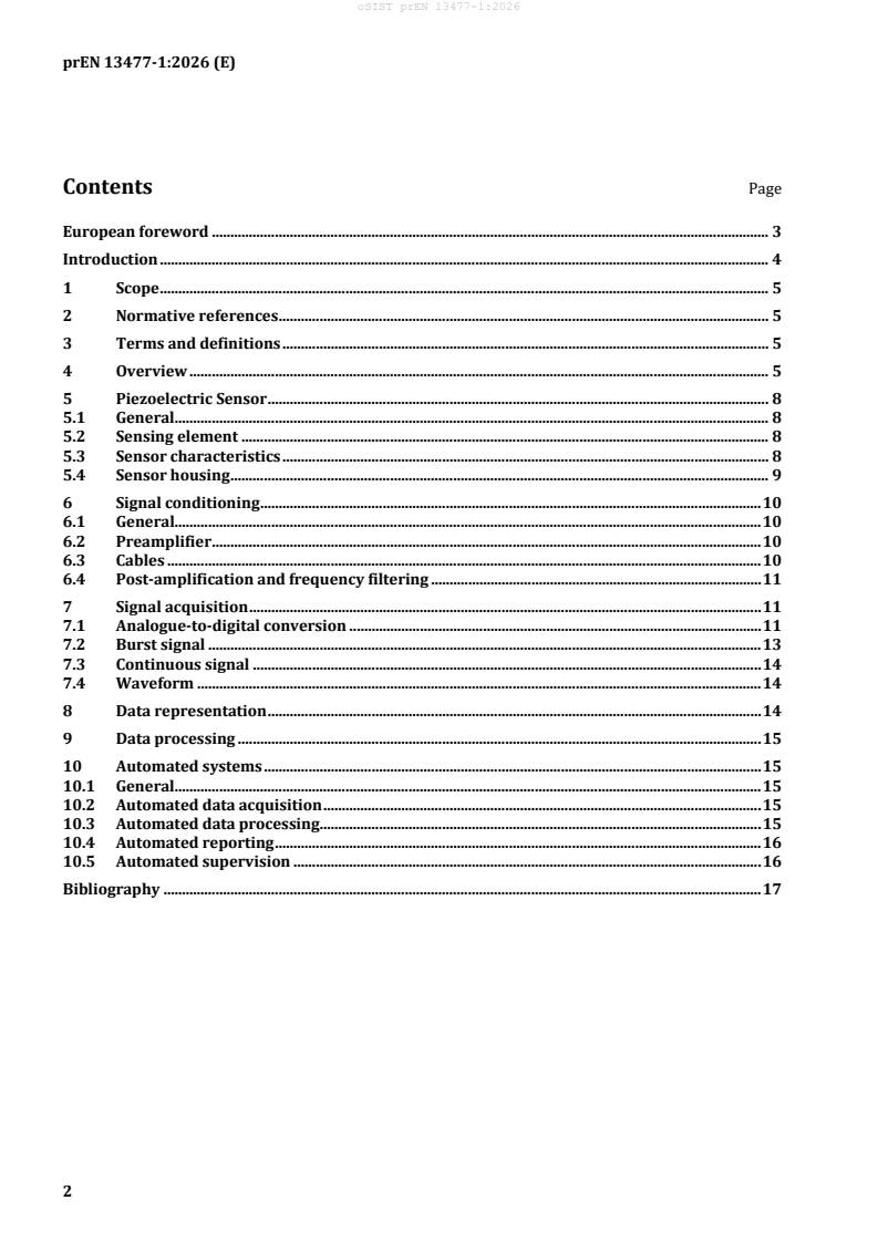
Contents Page
European foreword . 3
Introduction . 4
1 Scope . 5
2 Normative references . 5
3 Terms and definitions . 5
4 Overview . 5
5 Piezoelectric Sensor . 8
5.1 General. 8
5.2 Sensing element . 8
5.3 Sensor characteristics . 8
5.4 Sensor housing . 9
6 Signal conditioning . 10
6.1 General. 10
6.2 Preamplifier . 10
6.3 Cables . 10
6.4 Post-amplification and frequency filtering . 11
7 Signal acquisition . 11
7.1 Analogue-to-digital conversion . 11
7.2 Burst signal . 13
7.3 Continuous signal . 14
7.4 Waveform . 14
8 Data representation . 14
9 Data processing . 15
10 Automated systems . 15
10.1 General. 15
10.2 Automated data acquisition . 15
10.3 Automated data processing. 15
10.4 Automated reporting . 16
10.5 Automated supervision . 16
Bibliography . 17
prEN 13477-1:2026 (E)
European foreword
This document (prEN 13477-1:2026) has been prepared by Technical Committee CEN/TC 138
“Non-destructive testing”, the secretariat of which is held by AFNOR.
This document is currently submitted to the CEN Enquiry.
This document will supersede EN 13477-1:2001.
prEN 13477-1:2026 includes the following significant technical changes with respect to
EN 13477-1:2001:
— Clause 4 “Overview” added.
EN 13477, Non-destructive testing — Acoustic emission testing — Equipment characterization, consists
of the following parts:
— Part 1: Equipment description;
— Part 2: Verification of operating characteristics.
Part 1 of this document describes the main components of an acoustic emission testing system.
Part 2 of this document gives methods and acceptance criteria for verifying routinely the electronic
performance of an acoustic emission testing system composed of one or more acoustic emission
channels during its lifetime.
prEN 13477-1:2026 (E)
Introduction
Most of the acoustic emission testing systems for industrial applications are based on the utilization of
piezoelectric sensors. This sensor technology usually offers high sensitivity as well as reliability and is
sufficiently robust at the same time. Piezoelectric sensors have been used successfully for decades in
the field of acoustic emission testing and thus a wide range of different piezoelectric sensor types and
models produced by various equipment manufacturers are available.
Therefore, this document describes the equipment used for utilizing piezoelectric sensors as this
technology is the most widespread one.
prEN 13477-1:2026 (E)
1 Scope
This document describes the main components that constitute an acoustic emission testing system on
the basis of the utilization of piezoelectric sensors. Each component is assigned to one of the following
list items:
a) piezoelectric sensor;
b) signal conditioning;
c) signal acquisition;
d) analysis and output of results.
2 Normative references
The following documents are referred to in the text in such a way that some or all of their content
constitutes requirements of this document. For dated references, only the edition cited applies. For
undated references, the latest edition of the referenced document (including any amendments) applies.
EN 1330-1:2014, Non-destructive testing — Terminology — Part 1: List of general terms
EN 1330-2:1998, Non-destructive testing — Terminology — Part 2: Terms common to the non-destructive
testing methods
EN 1330-9:2017, Non-destructive testing — Terminology — Part 9: Terms used in acoustic emission
testing
3 Terms and definitions
For the purposes of this document, the terms and definitions given in EN 1330-1:2014, EN 1330-2:1998
and EN 1330-9:2017 apply.
ISO and IEC maintain terminology databases for use in standardization at the following addresses:
— ISO Online browsing platform: available at https://www.iso.org/obp/
— IEC Electropedia: available at https://www.electropedia.org/
4 Overview
The measurement chain employed in acoustic emission testing (AT) is based predominately on
piezoelectric sensors and can be divided into three sections: the piezoelectric sensor is designated as
section 1, the signal conditioning as section 2 and the signal acquisition as section 3.
The piezoelectric sensor is usually mounted directly onto the surface of the test object and constitutes
section 1 of each measurement chain for the detection of acoustic emission (AE) released in the course
of the test. Generally, the output signal of the sensor shall represent the characteristic response to the
surface displacement caused by the elastic wave arriving at the sensor's sensitive face. In case of burst
emission, the output signal of the sensor can be separated in time into single AE signals. In case of
continuous emission, a high number of burst emissions superpose so that no clear separation into
single burst emissions is possible anymore. However, the output signal due to continuous emission shall
be characteristic of the excitation at the sensor’s sensitive face as well.
prEN 13477-1:2026 (E)
The excitation at the sensitive face of such an AE sensor may be described by the normal component of
the surface displacement u at the sensor position x as a function of time t. Figure 1 a) shows an
XD
example in terms of the output signal voltage s in time t of a broadband capacitive sensor
C
(displacement sensor) in response to a single burst emission due to the breakage of a glass capillary at
the surface of a steel test block. The glass capillary is positioned in close vicinity to the capacitive sensor
and at the midway point to a resonant AE sensor so that the time of excitation by the surface pulse due
to the breakage of the glass capillary is equal for both sensors. The measurement setup as well as the
results are described in References [1], [2] and discussed further in Reference [3]. Figure 1 b) holds the
representation of the AE sensor response by the output signal voltage s in time t. The excitation of the
AE sensor is characterized by a rather distinct pulse-like shape, whereas the response of the AE sensor
to the excitation is an oscillating electrical signal with a rather sharp rise till to the maximum amplitude
followed by a less sharp decline. The comparison of both graphs, Figure 1 a) and Figure 1 b), underline
that the excitation of the sensor by a mechanical stimulus (i.e. the surface displacement) differs in
general from its response (i.e. the electrical signal). Only in the exceptional case of a displacement
sensor, the shape of the excitation and the respective response would be similar.
Key
s (t) output signal voltage (arbitrary units) of the broadband capacitive sensor as a function of time t
C
s(t) output signal voltage (arbitrary units) of the resonant AE sensor as a function of time t
Figure 1 — Excitation and response of a piezoelectric sensor in case of a surface pulse according
to reference [2], a) the output signal of the broadband capacitive sensor representing the
excitation and b) the output signal of a resonant AE sensor representing the response
Section 1 of the measurement chain, the AE sensor, provides the mechanical-to-electrical conversion for
burst emission detection and burst signal acquisition as depicted schematically in Figure 2.
Section 2 of the measurement chain, the signal conditioning, commences where the analogue electrical
signal at the sensor output is connected to the input of the impedance adapted preamplifier. The output
signal voltage of the AE sensor is amplified by the preamplifier gain between the lower and the upper
roll-off frequency of the built-in bandpass filter. The output of the preamplifier is capable to drive the
amplified AE signal over some 100 m to the input of the measurement board of the AE instrument
without significant distortion. Section 2 of the measurement chain is concluded when the signal has
passed the analogue filter of the measurement board (including a low-pass anti-aliasing filter).
Section 3 of the measurement chain, the signal acquisition, starts with the analogue-to-digital
conversion, where the analogue signal is converted at a given rate into a sequence of discrete samples.
prEN 13477-1:2026 (E)
The sampled signal is then sent to the digital signal processing unit (i.e. digital signal filtering), where
non-relevant frequency contents can be removed in a convenient way by selecting suited low-pass,
high-pass or notch filters when setting up the acquisition process. The main step of section 3 is the
conversion from the digital signal to the burst signal features.
Key
XD piezoelectric sensor, section 1 of the measurement chain
SC signal conditioning, section 2 of the measurement chain
SA signal acquisition, section 3 of the measurement chain
EW elastic wave arriving at the sensitive face of the sensor mounted onto the surface of the test object
ES electrical signal at the sensor output in response to the excitation at the input side
G(f) gain with respect to the frequency f within the bandwidth of the preamplifier
l length of the coaxial cable from the preamplifier output to the measurement board input
T(f) transmission of the high-pass and the low-pass (anti-aliasing) filter with respect to the frequency f
AS analogue signal at the input of the analogue-to-digital conversion
DS digital signal as the result of the analogue-to-digital conversion
s[i] digital signal voltage of sample i measured at time t[i]
DSP digital signal processing utilizing algorithms for low-pass, high-pass and notch filtering
BSF burst signal features as the result of a hit
WF burst signal waveform as the result of a hit
AED acoustic emission data
WFD waveform data
Figure 2 — Principle of the measurement chain for burst signal acquisition
prEN 13477-1:2026 (E)
A burst signal is detected when the measured signal voltage exceeds the first time the selected detection
threshold after a defined period without threshold crossings. The event of burst signal detection
constitutes a hit and triggers the determination of burst signal features (e.g. arrival time, measurement
channel number, maximum amplitude, rise time, duration, energy) as well as the registration of
additional information related to continuous signal features (e.g. background noise level). Further
information characteristic of the given conditions at the time of burst signal detection, for instance time
synchronized slow-varying parameter data (e.g. reading of a pressure gauge) acquired at a sampling
rate appropriate for the application and digitized by the AE instrument itself or by a separate measuring
instrument, should be added to the AE data set.
In the course of the data acquisition process for detection and characterization of burst signals, a
stream of AE data sets is generated and stored to the AE data. Optionally, the samples of the burst signal
can be stored as digitized representation for further analysis, what is called waveform recording. In this
case two separate but interrelated data bases are provided as the result of the acquisition process. At
the end of the section 3 of the measurement chain, AE data and waveform data are available for analysis
and output of results, on-line as well as off-line.
5 Piezoelectric Sensor
5.1 General
A piezoelectric sensor is the most commonly used device for detecting acoustic emission (AE). It
provides the most effective conversion of elastic waves into an electrical signal in the frequency range
most commonly used for AE detection, 20 kHz – 1 MHz. Usually, it consists of a piezoelectric ceramic
element mounted in a protective housing. The piezoelectric element is sensitive to different wave types
arriving from any direction at the sensor’s face: compressional, shear, surface (Rayleigh) and plate
(Lamb) waves.
5.2 Sensing element
The sensing material affects the conversion efficiency and operating temperature range. Lead zirconate
titanate (PZT), a ceramic, is the most commonly used materia
...