


ASTM D7418-12(2019)
(Practice)Standard Practice for Set-Up and Operation of Fourier Transform Infrared (FT-IR) Spectrometers for In-Service Oil Condition Monitoring
Standard Practice for Set-Up and Operation of Fourier Transform Infrared (FT-IR) Spectrometers for In-Service Oil Condition Monitoring
SIGNIFICANCE AND USE
4.1 This practice describes to the end user how to collect the FT-IR spectra of in-service oil samples for in-service oil condition monitoring. Various in-service oil condition monitoring parameters, such as oxidation, nitration, soot, water, ethylene glycol, fuel dilution, gasoline dilution, sulfate by-products and phosphate antiwear additives, can be measured by FT-IR spectroscopy (4-7), as described in Practice E2412. Changes in the values of these parameters over operating time can then be used to help diagnose the operational condition of various machinery and equipment and to indicate when an oil change should take place. This practice is intended to give a standardized configuration for FT-IR instrumentation and operating parameters employed in in-service oil condition monitoring in order to obtain comparable between-instrument and between-laboratory data.
SCOPE
1.1 This practice covers the instrument set-up and operation parameters for using FT-IR spectrometers for in-service oil condition monitoring for both direct trend analysis and differential trend analysis approaches.
1.2 This practice describes how to acquire the FT-IR spectrum of an in-service oil sample using a standard transmission cell and establishes maximum allowable spectral noise levels.
1.3 Measurement and integrated parameters for individual in-service oil condition monitoring components and parameters are not described in this practice and are described in their respective test methods.
1.4 The values stated in SI units are to be regarded as the standard. The values given in parentheses are for information only.
1.5 This standard does not purport to address all of the safety concerns, if any, associated with its use. It is the responsibility of the user of this standard to establish appropriate safety, health, and environmental practices and determine the applicability of regulatory limitations prior to use.
1.6 This international standard was developed in accordance with internationally recognized principles on standardization established in the Decision on Principles for the Development of International Standards, Guides and Recommendations issued by the World Trade Organization Technical Barriers to Trade (TBT) Committee.
General Information
Buy Standard
Standards Content (Sample)
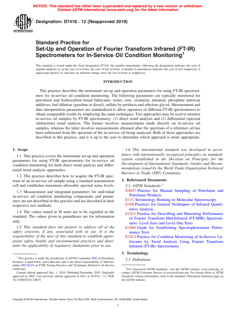
NOTICE: This standard has either been superseded and replaced by a new version or withdrawn.
Contact ASTM International (www.astm.org) for the latest information
Designation: D7418 − 12 (Reapproved 2019)
Standard Practice for
Set-Up and Operation of Fourier Transform Infrared (FT-IR)
Spectrometers for In-Service Oil Condition Monitoring
This standard is issued under the fixed designation D7418; the number immediately following the designation indicates the year of
original adoption or, in the case of revision, the year of last revision. A number in parentheses indicates the year of last reapproval. A
superscript epsilon (´) indicates an editorial change since the last revision or reapproval.
INTRODUCTION
This practice describes the instrument set-up and operation parameters for using FT-IR spectrom-
eters for in-service oil condition monitoring. The following parameters are typically monitored for
petroleum and hydrocarbon based lubricants: water, soot, oxidation, nitration, phosphate antiwear
additives, fuel dilution (gasoline or diesel), sulfate by-products and ethylene glycol. Measurement and
data interpretation parameters are standardized to allow operators of different FT-IR spectrometers to
obtaincomparableresultsbyemployingthesametechniques.Twoapproachesmaybeusedtomonitor
in-service oil samples by FT-IR spectrometry: (1) direct trend analysis and (2) differential (spectral
subtraction) trend analysis. The former involves measurements made directly on in-service oil
samples, whereas the latter involves measurements obtained after the spectrum of a reference oil has
been subtracted from the spectrum of the in-service oil being analyzed. Both of these approaches are
described in this practice, and it is up to the user to determine which approach is more appropriate.
1. Scope 1.6 This international standard was developed in accor-
dance with internationally recognized principles on standard-
1.1 This practice covers the instrument set-up and operation
ization established in the Decision on Principles for the
parameters for using FT-IR spectrometers for in-service oil
Development of International Standards, Guides and Recom-
condition monitoring for both direct trend analysis and differ-
mendations issued by the World Trade Organization Technical
ential trend analysis approaches.
Barriers to Trade (TBT) Committee.
1.2 This practice describes how to acquire the FT-IR spec-
2. Referenced Documents
trum of an in-service oil sample using a standard transmission
cell and establishes maximum allowable spectral noise levels.
2.1 ASTM Standards:
D4057 Practice for Manual Sampling of Petroleum and
1.3 Measurement and integrated parameters for individual
Petroleum Products
in-service oil condition monitoring components and param-
E131 Terminology Relating to Molecular Spectroscopy
etersarenotdescribedinthispracticeandaredescribedintheir
E168 Practices for General Techniques of Infrared Quanti-
respective test methods.
tative Analysis
1.4 The values stated in SI units are to be regarded as the
E1421 Practice for Describing and Measuring Performance
standard. The values given in parentheses are for information
of Fourier Transform Mid-Infrared (FT-MIR) Spectrom-
only.
eters: Level Zero and Level One Tests
1.5 This standard does not purport to address all of the
E1866 Guide for Establishing Spectrophotometer Perfor-
safety concerns, if any, associated with its use. It is the
mance Tests
responsibility of the user of this standard to establish appro-
E2412 Practice for Condition Monitoring of In-Service Lu-
priate safety, health, and environmental practices and deter-
bricants by Trend Analysis Using Fourier Transform
mine the applicability of regulatory limitations prior to use.
Infrared (FT-IR) Spectrometry
3. Terminology
This practice is under the jurisdiction ofASTM Committee D02 on Petroleum
3.1 Definitions:
Products, Liquid Fuels, and Lubricants and is the direct responsibility of Subcom-
mittee D02.96.03 on FTIR Testing Practices and Techniques Related to In-Service
Lubricants. For referenced ASTM standards, visit the ASTM website, www.astm.org, or
Current edition approved Dec. 1, 2019. Published December 2019. Originally contact ASTM Customer Service at service@astm.org. For Annual Book of ASTM
approved in 2007. Last previous edition approved in 2012 as D7418 – 12. DOI: Standards volume information, refer to the standard’s Document Summary page on
10.1520/D7418-12R19. the ASTM website.
Copyright © ASTM International, 100 Barr Harbor Drive, PO Box C700, West Conshohocken, PA 19428-2959. United States
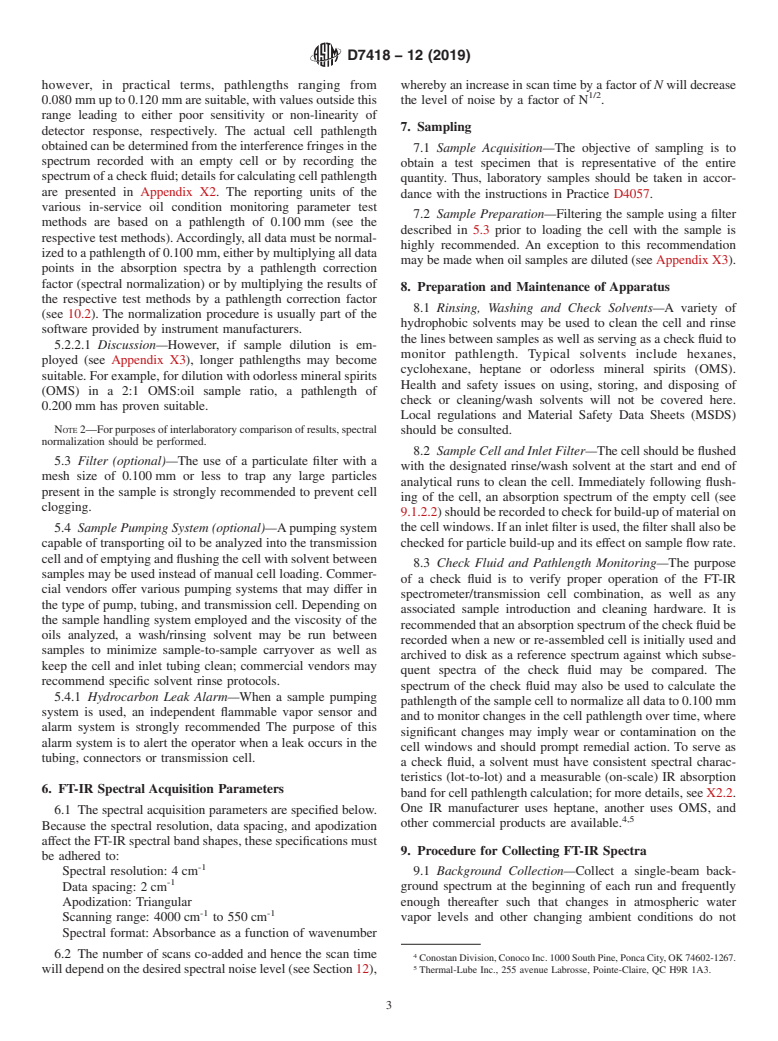
D7418 − 12 (2019)
3.1.1 For definitions of terms relating to infrared spectros- can then be used to help diagnose the operational condition of
copy used in this practice, refer to Terminology E131. various machinery and equipment and to indicate when an oil
3.1.2 Fourier transform infrared (FT-IR) spectrometry, change should take place. This practice is intended to give a
n—form of infrared spectrometry in which an interferogram is standardized configuration for FT-IR instrumentation and op-
obtained; this interferogram is then subjected to a Fourier erating parameters employed in in-service oil condition moni-
transform calculation to obtain an amplitude-wavenumber (or toring in order to obtain comparable between-instrument and
wavelength) spectrum. between-laboratory data.
3.2 Definitions of Terms Specific to This Standard:
5. Apparatus
3.2.1 condition monitoring, n—fieldoftechnicalactivityin
which selected physical parameters associated with an operat- 5.1 Fourier Transform Infrared (FT-IR) Spectrometer—All
ing machine are periodically or continuously sensed, measured
FT-IR instruments suitable for use in this practice must be
and recorded for the interim purpose of reducing, analyzing, configured with a source, beamsplitter and detector suitable for
-1
comparinganddisplayingthedataandinformationsoobtained
spectral acquisition over the mid-infrared range of 4000 cm
-1
and for the ultimate purpose of using interim result to support to 550 cm . The standard configuration includes a room
decisions related to the operation and maintenance of the
temperature deuterated triglycine sulfate (DTGS) detector, an
machine. (1, 2)
air-cooled source, and a germanium-coated potassium bromide
(Ge/KBr) beamsplitter, although a zinc selenide (ZnSe) beam-
3.2.2 direct trend analysis, n—monitoring of the level and
splitter may also be used. The FT-IR spectrometer’s IR source
rate of change over operating time of measured parameters (2,
and interferometer should be in a sealed compartment to
3) using the FT-IR spectrum of the in-service oil sample,
prevent harmful, flammable or explosive vapors from reaching
directly, without any spectral data manipulation such as spec-
the IR source.
tral subtraction.
3.2.3 differential trend analysis, n—monitoring of the level NOTE1—Photoconductivedetectorssuchasmercurycadmiumtelluride
(MCT) should not be used owing to inadequate linearity of the detector
and rate of change over operating time of measured parameters
response.
usingtheFT-IRspectraofthein-serviceoilsamples,following
5.2 Sample Cell—The sample cell employed for in-service
subtraction of the spectrum of the reference oil.
oil condition monitoring is a transmission cell with a fixed
3.2.4 in-service oil, n—lubricating oil that is present in a
pathlength that can be inserted in the optical path of the FT-IR
machine that has been at operating temperature for at least one
spectrometer. Cell window material and cell pathlength con-
hour.
siderations are stated below.
3.2.4.1 Discussion—Sampling an in-service oil after a short
5.2.1 Cell Window Material—ZnSe is commonly used as
period of operation will allow for the measurement of a base
the window material for condition monitoring and is recom-
point for trend analysis; the minimum sampling time should be
mended because of its resistance to water. Sample cells
at least one hour after oil change or topping-off.
constructed of materials other than ZnSe may be used;
3.2.5 reference oil, n—sample of a lubricating oil whose
however, to address all the various methods associated with
spectrum is subtracted from the spectrum of an in-service oil
condition monitoring, the window material should transmit IR
for differential trend analysis.
-1 -1
radiation over the range of 4000 cm to 550 cm . KCl and
3.2.5.1 Discussion—The most commonly employed refer-
KBr are common cell window materials that meet this require-
enceoilisasampleofthenewoil.Itshouldbenoted,however,
ment but these are water-soluble salts and should not be used
that the continued use of the same reference oil after any
if oil samples containing moisture are frequently run through
top-off of lubricant may lead to erroneous conclusions, unless
the cell, as contact with water will cause the windows to fog
the added lubricant is from the same lot and drum as the
and erode rapidly. In addition, Coates and Setti (8) have noted
in-service oil. This possibility is averted if a sample of the
that oil nitration products can react with KCl and KBr
in-service oil is taken after a short period of operation
windows, depositing compounds that are observed in the
following top-off of the lubricant (see 3.2.4.1) and is employed
spectra of later samples. On the basis of this report, KCl and
thereafter as the reference oil.
KBr windows should not be used with samples of gasoline or
natural gas engine oils as well as other types of lubricants
4. Significance and Use
where nitration by-products may form due to the combustion
4.1 Thispracticedescribestotheenduserhowtocollectthe
process or other routes of nitration formation.
FT-IR spectra of in-service oil samples for in-service oil
5.2.1.1 When ZnSe is used as the window material, the
condition monitoring. Various in-service oil condition moni-
reflections of the infrared beam that occur at the inner faces of
toring parameters, such as oxidation, nitration, soot, water,
the windows cause fringes to be superimposed on the oil
ethylene glycol, fuel dilution, gasoline dilution, sulfate by-
spectrum; these must be minimized using physical or compu-
productsandphosphateantiwearadditives,canbemeasuredby
tational techniques as presented in Appendix X1. Because KCl
FT-IR spectroscopy (4-7), as described in Practice E2412.
and KBr have lower refractive indices than ZnSe, the use of
Changes in the values of these parameters over operating time
these window materials avoids observable fringes in the oil
spectrum.
5.2.2 Cell Pathlength—The standard cell pathlength to be
The boldface numbers in parentheses refer to a list of references at the end of
this standard. employed for in-service oil condition monitoring is 0.100 mm;
D7418 − 12 (2019)
however, in practical terms, pathlengths ranging from whereby an increase in scan time by a factor of N will decrease
1/2
0.080 mmupto0.120 mmaresuitable,withvaluesoutsidethis the level of noise by a factor of N .
range leading to either poor sensitivity or non-linearity of
7. Sampling
detector response, respectively. The actual cell pathlength
obtained can be determined from the interference fringes in the
7.1 Sample Acquisition—The objective of sampling is to
spectrum recorded with an empty cell or by recording the
obtain a test specimen that is representative of the entire
spectrumofacheckfluid;detailsforcalculatingcellpathlength
quantity. Thus, laboratory samples should be taken in accor-
are presented in Appendix X2. The reporting units of the
dance with the instructions in Practice D4057.
various in-service oil condition monitoring parameter test
7.2 Sample Preparation—Filtering the sample using a filter
methods are based on a pathlength of 0.100 mm (see the
described in 5.3 prior to loading the cell with the sample is
respective test methods).Accordingly, all data must be normal-
highly recommended. An exception to this recommendation
izedtoapathlengthof0.100 mm,eitherbymultiplyingalldata
may be made when oil samples are diluted (see Appendix X3).
points in the absorption spectra by a pathlength correction
factor (spectral normalization) or by multiplying the results of
8. Preparation and Maintenance of Apparatus
the respective test methods by a pathlength correction factor
8.1 Rinsing, Washing and Check Solvents—A variety of
(see 10.2). The normalization procedure is usually part of the
hydrophobic solvents may be used to clean the cell and rinse
software provided by instrument manufacturers.
the lines between samples as well as serving as a check fluid to
5.2.2.1 Discussion—However, if sample dilution is em-
monitor pathlength. Typical solvents include hexanes,
ployed (see Appendix X3), longer pathlengths may become
cyclohexane, heptane or odorless mineral spirits (OMS).
suitable.Forexample,fordilutionwithodorlessmineralspirits
Health and safety issues on using, storing, and disposing of
(OMS) in a 2:1 OMS:oil sample ratio, a pathlength of
check or cleaning/wash solvents will not be covered here.
0.200 mm has proven suitable.
Local regulations and Material Safety Data Sheets (MSDS)
NOTE2—Forpurposesofinterlaboratorycomparisonofresults,spectral
should be consulted.
normalization should be performed.
8.2 Sample Cell and Inlet Filter—Thecellshouldbeflushed
5.3 Filter (optional)—The use of a particulate filter with a
with the designated rinse/wash solvent at the start and end of
mesh size of 0.100 mm or less to trap any large particles
analytical runs to clean the cell. Immediately following flush-
present in the sample is strongly recommended to prevent cell
ing of the cell, an absorption spectrum of the empty cell (see
clogging.
9.1.2.2)shouldberecordedtocheckforbuild-upofmaterialon
5.4 Sample Pumping System (optional)—Apumping system thecellwindows.Ifaninletfilterisused,thefiltershallalsobe
checkedforparticlebuild-upanditseffectonsampleflowrate.
capable of transporting oil to be analyzed into the transmission
cellandofemptyingandflushingthecellwithsolventbetween
8.3 Check Fluid and Pathlength Monitoring—The purpose
samples may be used instead of manual cell loading. Commer-
of a check fluid is to verify proper operation of the FT-IR
cial vendors offer various pumping systems that may differ in
spectrometer/transmission cell combination, as well as any
the type of pump, tubing, and transmission cell. Depending on
associated sample introduction and cleaning hardware. It is
the sample handling system employed and the viscosity of the
recommendedthatanabsorptionspectrumofthecheckfluidbe
oils analyzed, a wash/rinsing solvent may be run between
recorded when a new or re-assembled cell is initially used and
samples to minimize sample-to-sample carryover as well as
archived to disk as a reference spectrum against which subse-
keep the cell and inlet tubing clean; commercial vendors may
quent spectra of the check fluid may be compared. The
recommend specific solvent rinse protocols
...
This document is not an ASTM standard and is intended only to provide the user of an ASTM standard an indication of what changes have been made to the previous version. Because
it may not be technically possible to adequately depict all changes accurately, ASTM recommends that users consult prior editions as appropriate. In all cases only the current version
of the standard as published by ASTM is to be considered the official document.
Designation: D7418 − 12 D7418 − 12 (Reapproved 2019)
Standard Practice for
Set-Up and Operation of Fourier Transform Infrared (FT-IR)
Spectrometers for In-Service Oil Condition Monitoring
This standard is issued under the fixed designation D7418; the number immediately following the designation indicates the year of
original adoption or, in the case of revision, the year of last revision. A number in parentheses indicates the year of last reapproval. A
superscript epsilon (´) indicates an editorial change since the last revision or reapproval.
INTRODUCTION
This practice describes the instrument set-up and operation parameters for using FT-IR spectrom-
eters for in-service oil condition monitoring. The following parameters are typically monitored for
petroleum and hydrocarbon based lubricants: water, soot, oxidation, nitration, phosphate antiwear
additives, fuel dilution (gasoline or diesel), sulfate by-products and ethylene glycol. Measurement and
data interpretation parameters are standardized to allow operators of different FT-IR spectrometers to
obtain comparable results by employing the same techniques. Two approaches may be used to monitor
in-service oil samples by FT-IR spectrometry: (1) direct trend analysis and (2) differential (spectral
subtraction) trend analysis. The former involves measurements made directly on in-service oil
samples, whereas the latter involves measurements obtained after the spectrum of a reference oil has
been subtracted from the spectrum of the in-service oil being analyzed. Both of these approaches are
described in this practice, and it is up to the user to determine which approach is more appropriate.
1. Scope
1.1 This practice covers the instrument set-up and operation parameters for using FT-IR spectrometers for in-service oil
condition monitoring for both direct trend analysis and differential trend analysis approaches.
1.2 This practice describes how to acquire the FT-IR spectrum of an in-service oil sample using a standard transmission cell and
establishes maximum allowable spectral noise levels.
1.3 Measurement and integrated parameters for individual in-service oil condition monitoring components and parameters are
not described in this practice and are described in their respective test methods.
1.4 The values stated in SI units are to be regarded as the standard. The values given in parentheses are for information only.
1.5 This standard does not purport to address all of the safety concerns, if any, associated with its use. It is the responsibility
of the user of this standard to establish appropriate safety safety, health, and healthenvironmental practices and determine the
applicability of regulatory limitations prior to use.
1.6 This international standard was developed in accordance with internationally recognized principles on standardization
established in the Decision on Principles for the Development of International Standards, Guides and Recommendations issued
by the World Trade Organization Technical Barriers to Trade (TBT) Committee.
2. Referenced Documents
2.1 ASTM Standards:
D4057 Practice for Manual Sampling of Petroleum and Petroleum Products
E131 Terminology Relating to Molecular Spectroscopy
E168 Practices for General Techniques of Infrared Quantitative Analysis
E1421 Practice for Describing and Measuring Performance of Fourier Transform Mid-Infrared (FT-MIR) Spectrometers: Level
Zero and Level One Tests
This practice is under the jurisdiction of ASTM Committee D02 on Petroleum Products, Liquid Fuels, and Lubricants and is the direct responsibility of Subcommittee
D02.96.03 on FTIR Testing Practices and Techniques Related to In-Service Lubricants.
Current edition approved Dec. 1, 2012Dec. 1, 2019. Published December 2012December 2019. Originally approved in 2007. lastLast previous edition approved in
20072012 as D7418 – 07.12. DOI: 10.1520/D7418-12.10.1520/D7418-12R19.
For referenced ASTM standards, visit the ASTM website, www.astm.org, or contact ASTM Customer Service at service@astm.org. For Annual Book of ASTM Standards
volume information, refer to the standard’s Document Summary page on the ASTM website.
Copyright © ASTM International, 100 Barr Harbor Drive, PO Box C700, West Conshohocken, PA 19428-2959. United States
D7418 − 12 (2019)
E1866 Guide for Establishing Spectrophotometer Performance Tests
E2412 Practice for Condition Monitoring of In-Service Lubricants by Trend Analysis Using Fourier Transform Infrared (FT-IR)
Spectrometry
3. Terminology
3.1 Definitions:
3.1.1 For definitions of terms relating to infrared spectroscopy used in this practice, refer to Terminology E131.
3.1.2 Fourier transform infrared (FT-IR) spectrometry, n—form of infrared spectrometry in which an interferogram is obtained;
this interferogram is then subjected to a Fourier transform calculation to obtain an amplitude-wavenumber (or wavelength)
spectrum.
3.2 Definitions of Terms Specific to This Standard:
3.2.1 condition monitoring, n— field of technical activity in which selected physical parameters associated with an operating
machine are periodically or continuously sensed, measured and recorded for the interim purpose of reducing, analyzing, comparing
and displaying the data and information so obtained and for the ultimate purpose of using interim result to support decisions related
to the operation and maintenance of the machine. (1, 2)
3.2.2 direct trend analysis, n—monitoring of the level and rate of change over operating time of measured parameters (2, 3)
using the FT-IR spectrum of the in-service oil sample, directly, without any spectral data manipulation such as spectral subtraction.
3.2.3 differential trend analysis, n—monitoring of the level and rate of change over operating time of measured parameters using
the FT-IR spectra of the in-service oil samples, following subtraction of the spectrum of the reference oil.
3.2.4 in-service oil, n—lubricating oil that is present in a machine that has been at operating temperature for at least one hour.
3.2.4.1 Discussion—
Sampling an in-service oil after a short period of operation will allow for the measurement of a base point for trend analysis; the
minimum sampling time should be at least one hour after oil change or topping-off.
3.2.5 reference oil, n—sample of a lubricating oil whose spectrum is subtracted from the spectrum of an in-service oil for
differential trend analysis.
3.2.5.1 Discussion—
The most commonly employed reference oil is a sample of the new oil. It should be noted, however, that the continued use of the
same reference oil after any top-off of lubricant may lead to erroneous conclusions, unless the added lubricant is from the same
lot and drum as the in-service oil. This possibility is averted if a sample of the in-service oil is taken after a short period of operation
following top-off of the lubricant (see 3.2.4.1) and is employed thereafter as the reference oil.
4. Significance and Use
4.1 This practice describes to the end user how to collect the FT-IR spectra of in-service oil samples for in-service oil condition
monitoring. Various in-service oil condition monitoring parameters, such as oxidation, nitration, soot, water, ethylene glycol, fuel
dilution, gasoline dilution, sulfate by-products and phosphate antiwear additives, can be measured by FT-IR spectroscopy (4-7),
as described in Practice E2412. Changes in the values of these parameters over operating time can then be used to help diagnose
the operational condition of various machinery and equipment and to indicate when an oil change should take place. This practice
is intended to give a standardized configuration for FT-IR instrumentation and operating parameters employed in in-service oil
condition monitoring in order to obtain comparable between-instrument and between-laboratory data.
5. Apparatus
5.1 Fourier Transform Infrared (FT-IR) Spectrometer—All FT-IR instruments suitable for use in this practice must be
-1
configured with a source, beamsplitter and detector suitable for spectral acquisition over the mid-infrared range of 40004000 cm
-1
to 550 cm550 cm . The standard configuration includes a room temperature deuterated triglycine sulfate (DTGS) detector, an
air-cooled source, and a germanium-coated potassium bromide (Ge/KBr) beamsplitter, although a zinc selenide (ZnSe)
beamsplitter may also be used. The FT-IR spectrometer’s IR source and interferometer should be in a sealed compartment to
prevent harmful, flammable or explosive vapors from reaching the IR source.
NOTE 1—Photoconductive detectors such as mercury cadmium telluride (MCT) should not be used owing to inadequate linearity of the detector
response.
The boldface numbers in parentheses refer to a list of references at the end of this standard.
D7418 − 12 (2019)
5.2 Sample Cell—The sample cell employed for in-service oil condition monitoring is a transmission cell with a fixed pathlength
that can be inserted in the optical path of the FT-IR spectrometer. Cell window material and cell pathlength considerations are
stated below.
5.2.1 Cell Window Material—ZnSe is commonly used as the window material for condition monitoring and is recommended
because of its resistance to water. Sample cells constructed of materials other than ZnSe may be used; however, to address all the
various methods associated with condition monitoring, the window material should transmit IR radiation over the range of 4000
-1 -1
cm4000 cm to 550 cm550 cm . KCl and KBr are common cell window materials that meet this requirement but these are
water-soluble salts and should not be used if oil samples containing moisture are frequently run through the cell, as contact with
water will cause the windows to fog and erode rapidly. In addition, Coates and Setti (8) have noted that oil nitration products can
react with KCl and KBr windows, depositing compounds that are observed in the spectra of later samples. On the basis of this
report, KCl and KBr windows should not be used with samples of gasoline or natural gas engine oils as well as other types of
lubricants where nitration by-products may form due to the combustion process or other routes of nitration formation.
5.2.1.1 When ZnSe is used as the window material, the reflections of the infrared beam that occur at the inner faces of the
windows cause fringes to be superimposed on the oil spectrum; these must be minimized using physical or computational
techniques as presented in Appendix X1. Because KCl and KBr have lower refractive indices than ZnSe, the use of these window
materials avoids observable fringes in the oil spectrum.
5.2.2 Cell Pathlength—The standard cell pathlength to be employed for in-service oil condition monitoring is 0.100 mm;
0.100 mm; however, in practical terms, pathlengths ranging from 0.0800.080 mm up to 0.120 mm 0.120 mm are suitable, with
values outside this range leading to either poor sensitivity or non-linearity of detector response, respectively. The actual cell
pathlength obtained can be determined from the interference fringes in the spectrum recorded with an empty cell or by recording
the spectrum of a check fluid; details for calculating cell pathlength are presented in Appendix X2. The reporting units of the
various in-service oil condition monitoring parameter test methods are based on a pathlength of 0.100 mm 0.100 mm (see the
respective test methods). Accordingly, all data must be normalized to a pathlength of 0.100 mm, 0.100 mm, either by multiplying
all data points in the absorption spectra by a pathlength correction factor (spectral normalization) or by multiplying the results of
the respective test methods by a pathlength correction factor (see 10.2). The normalization procedure is usually part of the software
provided by instrument manufacturers.
5.2.2.1 Discussion—However, if sample dilution is employed (see Appendix X3), longer pathlengths may become suitable. For
example, for dilution with odorless mineral spirits (OMS) in a 2:1 OMS:oil sample ratio, a pathlength of 0.200 mm 0.200 mm has
proven suitable.
NOTE 2—For purposes of interlaboratory comparison of results, spectral normalization should be performed.
5.3 Filter (optional)—The use of a particulate filter with a mesh size of 0.100 mm 0.100 mm or less to trap any large particles
present in the sample is strongly recommended to prevent cell clogging.
5.4 Sample Pumping System (optional)—A pumping system capable of transporting oil to be analyzed into the transmission cell
and of emptying and flushing the cell with solvent between samples may be used instead of manual cell loading. Commercial
vendors offer various pumping systems that may differ in the type of pump, tubing, and transmission cell. Depending on the sample
handling system employed and the viscosity of the oils analyzed, a wash/rinsing solvent may be run between samples to minimize
sample-to-sample carryover as well as keep the cell and inlet tubing clean; commercial vendors may recommend specific solvent
rinse protocols.
5.4.1 Hydrocarbon Leak Alarm—When a sample pumping system is used, an independent flammable vapor sensor and alarm
system is strongly recommended The purpose of this alarm system is to alert the operator when a leak occurs in the tubing,
connectors or transmission cell.
6. FT-IR Spectral Acquisition Parameters
6.1 The spectral acquisition parameters are specified below. Because the spectral resolution, data spacing, and apodization affect
the FT-IR spectral band shapes, these specifications must be adhered to:
-1
Spectral resolution: 4 cm4 cm
-1
Data spacing: 2 cm2 cm
Apodization: Triangular
-1 -1
Scanning range: 40004000 cm to 550 cm550 cm
Spectral format: Absorbance as a function of wavenumber
6.2 The number of scans co-added and hence the scan time will depend on the desired spectral noise level (see Section 12),
1/2
whereby an increase in scan time by a factor of N will decrease the level of noise by a factor of N .
7. Sampling
7.1 Sample Acquisition—The objective of sampling is to obtain a test specimen that is representative of the entire quantity. Thus,
laboratory samples should be taken in accordance with the instructions in Practice D4057.
D7418 − 12 (2019)
7.2 Sample Preparation—Filtering the sample using a filter described in 5.3 prior to loading the cell with the sample is highly
recommended. An exception to this recommendation may be made when oil samples ar
...
Questions, Comments and Discussion
Ask us and Technical Secretary will try to provide an answer. You can facilitate discussion about the standard in here.