


ASTM C1326-13(2018)
(Test Method)Standard Test Method for Knoop Indentation Hardness of Advanced Ceramics
Standard Test Method for Knoop Indentation Hardness of Advanced Ceramics
SIGNIFICANCE AND USE
5.1 For advanced ceramics, Knoop indenters are used to create indentations. The surface projection of the long diagonal is measured with optical microscopes.
5.2 The Knoop indentation hardness is one of many properties that is used to characterize advanced ceramics. Attempts have been made to relate Knoop indentation hardness to other hardness scales, but no generally accepted methods are available. Such conversions are limited in scope and should be used with caution, except for special cases where a reliable basis for the conversion has been obtained by comparison tests.
5.3 For advanced ceramics, the Knoop indentation is often preferred to the Vickers indentation since the Knoop long diagonal length is 2.8 times longer than the Vickers diagonal for the same force, and cracking is much less of a problem (1).5 On the other hand, the long slender tip of the Knoop indentation is more difficult to precisely discern, especially in materials with low contrast. The indentation forces chosen in this test method are designed to produce indentations as large as may be possible with conventional microhardness equipment, yet not so large as to cause cracking.
5.4 The Knoop indentation is shallower than Vickers indentations made at the same force. Knoop indents may be useful in evaluating coating hardnesses.
5.5 Knoop hardness is calculated from the ratio of the applied force divided by the projected indentation area on the specimen surface. It is assumed that the elastic springback of the narrow diagonal is negligible. (Vickers indenters are also used to measure hardness, but Vickers hardness is calculated from the ratio of applied force to the area of contact of the four faces of the undeformed indenter.)
5.6 A full hardness characterization includes measurements over a broad range of indentation forces. Knoop hardness of ceramics usually decreases with increasing indentation size or indentation force such as that shown in Fig. 1.6 The trend is known as the in...
SCOPE
1.1 This test method covers the determination of the Knoop indentation hardness of advanced ceramics. In this test, a pointed, rhombic-based, pyramidal diamond indenter of prescribed shape is pressed into the surface of a ceramic with a predetermined force to produce a relatively small, permanent indentation. The surface projection of the long diagonal of the permanent indentation is measured using a light microscope. The length of the long diagonal and the applied force are used to calculate the Knoop hardness which represents the material’s resistance to penetration by the Knoop indenter.
1.2 The values stated in SI units are to be regarded as standard. No other units of measurement are included in this standard.
1.3 Units—When Knoop and Vickers hardness tests were developed, the force levels were specified in units of grams-force (gf) and kilograms-force (kgf). This standard specifies the units of force and length in the International System of Units (SI); that is, force in newtons (N) and length in mm or μm. However, because of the historical precedent and continued common usage, force values in gf and kgf units are occasionally provided for information. This test method specifies that Knoop hardness be reported either in units of GPa or as a dimensionless Knoop hardness number.
1.4 This standard does not purport to address all of the safety concerns, if any, associated with its use. It is the responsibility of the user of this standard to establish appropriate safety, health, and environmental practices and determine the applicability of regulatory limitations prior to use.
1.5 This international standard was developed in accordance with internationally recognized principles on standardization established in the Decision on Principles for the Development of International Standards, Guides and Recommendations issued by the World Trade Organization Technical Barriers to Trade (TBT) Committee.
General Information
Buy Standard
Standards Content (Sample)
NOTICE: This standard has either been superseded and replaced by a new version or withdrawn.
Contact ASTM International (www.astm.org) for the latest information
Designation: C1326 − 13 (Reapproved 2018)
Standard Test Method for
Knoop Indentation Hardness of Advanced Ceramics
This standard is issued under the fixed designation C1326; the number immediately following the designation indicates the year of
original adoption or, in the case of revision, the year of last revision. A number in parentheses indicates the year of last reapproval. A
superscript epsilon (´) indicates an editorial change since the last revision or reapproval.
1. Scope 2. Referenced Documents
2.1 ASTM Standards:
1.1 This test method covers the determination of the Knoop
C730 Test Method for Knoop Indentation Hardness of Glass
indentation hardness of advanced ceramics. In this test, a
C849 Test Method for Knoop Indentation Hardness of Ce-
pointed, rhombic-based, pyramidal diamond indenter of pre-
ramic Whitewares
scribed shape is pressed into the surface of a ceramic with a
E4 Practices for Force Verification of Testing Machines
predetermined force to produce a relatively small, permanent
E177 Practice for Use of the Terms Precision and Bias in
indentation. The surface projection of the long diagonal of the
ASTM Test Methods
permanent indentation is measured using a light microscope.
E384 Test Method for Microindentation Hardness of Mate-
The length of the long diagonal and the applied force are used
rials
to calculate the Knoop hardness which represents the material’s
E691 Practice for Conducting an Interlaboratory Study to
resistance to penetration by the Knoop indenter.
Determine the Precision of a Test Method
1.2 The values stated in SI units are to be regarded as
IEEE/ASTM SI 10 Standard for Use of the International
standard. No other units of measurement are included in this
System of Units (SI) (The Modern Metric System)
standard. 3
2.2 European Standard:
CEN ENV 843-4 Advanced Technical Ceramics, Monolithic
1.3 Units—When Knoop and Vickers hardness tests were
Ceramics, Mechanical Properties at Room Temperature,
developed, the force levels were specified in units of grams-
Part 4: Vickers, Knoop, and Rockwell Superficial Hard-
force (gf) and kilograms-force (kgf). This standard specifies
ness Tests
the units of force and length in the International System of
2.3 ISO Standard:
Units (SI); that is, force in newtons (N) and length in mm or
ISO 9385 Glass and Glass Ceramics—Knoop Hardness Test
µm. However, because of the historical precedent and contin-
ued common usage, force values in gf and kgf units are
3. Terminology
occasionally provided for information. This test method speci-
3.1 Definitions:
fies that Knoop hardness be reported either in units of GPa or
3.1.1 Knoop hardness number (HK), n—an expression of
as a dimensionless Knoop hardness number.
hardness obtained by dividing the force applied to the Knoop
1.4 This standard does not purport to address all of the
indenter by the projected area of the permanent impression
safety concerns, if any, associated with its use. It is the
made by the indenter.
responsibility of the user of this standard to establish appro-
3.1.2 Knoop indenter, n—a rhombic-based pyramidal-
priate safety, health, and environmental practices and deter-
shaped diamond indenter with edge angles of 172° 30' and
mine the applicability of regulatory limitations prior to use.
130° 00'.
1.5 This international standard was developed in accor-
dance with internationally recognized principles on standard-
4. Summary of Test Method
ization established in the Decision on Principles for the
4.1 This test method describes an indentation hardness test
Development of International Standards, Guides and Recom-
using a calibrated machine to force a pointed, rhombic-based,
mendations issued by the World Trade Organization Technical
Barriers to Trade (TBT) Committee.
For referenced ASTM standards, visit the ASTM website, www.astm.org, or
contact ASTM Customer Service at service@astm.org. For Annual Book of ASTM
Standards volume information, refer to the standard’s Document Summary page on
This test method is under the jurisdiction of ASTM Committee C28 on the ASTM website.
Advanced Ceramics and is the direct responsibility of Subcommittee C28.01 on Available from European Committee for Standardization (CEN), 36 rue de
Mechanical Properties and Performance. Stassart, B-1050, Brussels, Belgium, http://www.cenorm.be.
Current edition approved Jan. 1, 2018. Published January 2018. Originally Available from International Organization for Standardization (ISO), 1, ch. de
approved in 1996. Last previous edition approved in 2013 as C1326 – 13. DOI: la Voie-Creuse, Case postale 56, CH-1211, Geneva 20, Switzerland, http://
10.1520/C1326-13R18. www.iso.ch.
Copyright © ASTM International, 100 Barr Harbor Drive, PO Box C700, West Conshohocken, PA 19428-2959. United States
C1326 − 13 (2018)
pyramidal diamond indenter having specified face angles,
under a predetermined force, into the surface of the material
under test and measures the surface projection of the long
diagonal of the resulting impression after removal of the load.
NOTE 1—A general description of the Knoop indentation hardness test
is given in Test Method E384. The present test method differs from this
description only in areas required by the special nature of advanced
ceramics.
NOTE 2—This test method is similar to Test Methods C730 and C849,
but differs primarily in the choice of force and the rate of force application.
In addition, the length correction factor for the resolution limits of optical
microscopes is not utilized.
5. Significance and Use
5.1 For advanced ceramics, Knoop indenters are used to
create indentations. The surface projection of the long diagonal
is measured with optical microscopes.
5.2 The Knoop indentation hardness is one of many prop-
erties that is used to characterize advanced ceramics. Attempts
have been made to relate Knoop indentation hardness to other
hardness scales, but no generally accepted methods are avail-
able. Such conversions are limited in scope and should be used
with caution, except for special cases where a reliable basis for
the conversion has been obtained by comparison tests.
5.3 For advanced ceramics, the Knoop indentation is often
preferred to the Vickers indentation since the Knoop long
diagonal length is 2.8 times longer than the Vickers diagonal
FIG. 1 A Typical Indentation Size Effect (ISE) Curve for a Ceramic
(The data shown are for NIST SRM 2830 silicon nitride)
for the same force, and cracking is much less of a problem (1).
On the other hand, the long slender tip of the Knoop indenta-
tion is more difficult to precisely discern, especially in mate-
rials with low contrast. The indentation forces chosen in this
sufficiently large that hardness is either close to or on the
test method are designed to produce indentations as large as
plateau, but not so large as to introduce excessive cracking. A
may be possible with conventional microhardness equipment,
comprehensive characterization of the ISE is recommended but
yet not so large as to cause cracking.
is beyond the scope of this test method which measures
5.4 The Knoop indentation is shallower than Vickers inden-
hardness at a single, designated force.
tations made at the same force. Knoop indents may be useful in
evaluating coating hardnesses.
6. Interferences
5.5 Knoop hardness is calculated from the ratio of the
6.1 Cracking from the indentation tips can interfere with
applied force divided by the projected indentation area on the
interpretation of the exact tip location. The forces chosen for
specimen surface. It is assumed that the elastic springback of
this test method are sufficiently low that tip cracking, if it
the narrow diagonal is negligible. (Vickers indenters are also
occurs, will cause tiny, rather tight cracks at the indentation tips
used to measure hardness, but Vickers hardness is calculated
in advanced ceramics. Such cracks will have a negligible
from the ratio of applied force to the area of contact of the four
interference on measurements of the long diagonal length (2)
faces of the undeformed indenter.)
(unlike Vickers indentations in ceramics).
5.6 A full hardness characterization includes measurements
6.2 Cracking or spalling from the sides of the Knoop
over a broad range of indentation forces. Knoop hardness of
impression may also occur, possibly in a time-dependent
ceramics usually decreases with increasing indentation size or
manner (minutes or hours) after the impression is made. Small
indentation force such as that shown in Fig. 1. The trend is
amounts of such lateral cracking have little or no influence
known as the indentation size effect (ISE). Hardness ap-
upon measured hardness, provided that the tip impressions are
proaches a plateau constant hardness at sufficiently large
still readable and the tips are not dislodged (2).
indentation size or forces (loads). The test forces that are
6.3 Porosity (either on or just below the surface) may
needed to achieve a constant hardness vary with the ceramic.
interfere with measuring Knoop hardness, especially if the
The test force specified in this standard is intended to be
indentation falls directly onto a large pore or if the indentation
tip falls in a pore.
The boldface numbers in parentheses refer to the list of references at the end of
6.4 At higher magnifications in the optical microscope, it
this test method.
6 may be difficult to obtain a sharp contrast between the
Standard Reference Materials Program (NIST) 100 Bureau Drive, Stop 2300
Gaithersburg, MD 20899-2300. indentation tip and the polished surface of some advanced
C1326 − 13 (2018)
ceramics. This may be overcome by careful adjustment of the dimensions. The diagonals have an approximate ratio of 7:1,
lighting as discussed in Test Method E384 and Refs (2, 3). and the depth of the indentation is approximately ⁄30 the length
of the long diagonal. A perfect Knoop indenter has the
7. Apparatus
following angles:
7.1 Testing Machines:
7.2.2.1 Included longitudinal angle 172° 30 min 00 s.
7.1.1 There are three general types of machines available for
7.2.2.2 Included transverse angle 130° 00 min 00 s.
making this test. One type is a self-contained unit built for this
7.2.3 The constant C (defined in 12.2) for a perfect indenter
p
purpose that uses deadweights (masses) on a pan or lever beam
is 0.07028. The specifications require a variation of not more
to carefully apply force to the test piece. There is no load cell
than 1 % from this value.
to record the force during the test sequence. The machine has
7.2.4 The offset at the indenter tip shall not exceed 1.0 µm.
a built-in compound optical microscope for measuring the
See Test Method E384.
indentation sizes. The second type is an accessory to existing
7.2.5 The four faces of the indenter shall meet at sharp
compound optical microscopes. Usually, this second type is
edges.
fitted on an inverted-stage microscope. The third, more modern
7.2.6 The diamond should be examined periodically, and if
type, is a self-contained unit built for this purpose which has a
it is loose in the mounting material, chipped, or cracked, it shall
built-in load cell that controls a ram or crosshead that moves
be replaced.
the indenter into contact with the test piece. The peak force and
rate of force application can be controlled by a closed-loop NOTE 3—This requirement is from Test Method E384 and is especially
pertinent to diamond indenters that are used to measure hardness of
feedback circuit. The machine has a built-in compound optical
ceramics. In addition, these indenters sometimes are used to precrack
microscope for measuring the indentation sizes. Descriptions
advanced ceramic specimens at loads higher than customarily used for
of the various machines are available (4-6).
hardness testing. Such usage can lead to indenter damage. The diamond
7.1.2 Design of the machine should be such that the loading
indenter can be examined with a scanning electron microscope, or indents
can be made into soft copper to help determine if a chip or crack is present.
rate, dwell time, and applied load can be set within the limits
Indenters may also be inspected with an optical microscope with at least
set forth in 10.5. It is an advantage to eliminate the human
500× power, but care should be taken to avoid damaging the microscope
element whenever possible by appropriate machine design.
lens.
The machine should be designed so that vibrations induced at
7.3 Measuring Microscope:
the beginning of a test will be damped out by the time the
7.3.1 The measurement system shall be constructed so that
indenter touches the sample.
the length of the diagonals can be determined with errors not
7.1.3 The calibration of the balance beam or force applica-
exceeding 60.0005 mm.
tion system should be checked monthly or as needed. Inden-
tations in standard reference materials may also be used to
NOTE 4—Stage micrometers with uncertainties less than this shall be
check calibration when needed.
used to establish calibration constants for the microscope. See Test
Method E384. Ordinary stage micrometers which are used for determining
7.2 Indenter:
the approximate magnification of photographs may be ruled too coarse or
7.2.1 The indenter shall meet the specifications for Knoop
may not have the required accuracy and precision.
indenters. See Test Method E384.
7.3.2 The numerical aperture (NA) of the objective lens
7.2.2 Fig. 2 shows the indenter and its maximum usable
shall be between 0.60 and 0.90.
NOTE 5—The apparent length of a Knoop indentation will increase as
the resolving power and NA of a lens increases. The range of NA specified
by this test method corresponds to 40 to 100× objective lenses. The
higher-power lenses may have higher resolution, but the contrast between
the indentation tips and the polished surface may be less.
7.3.3 A filter may be used to provide monochromatic
illumination. Green filters have proved to be useful.
8. Test Specimens
8.1 The Knoop indentation hardness test is adaptable to a
wide variety of advanced ceramic specimens. In general, the
accuracy of the test will depend on the smoothness of the
surface and, whenever possible, ground and polished speci-
mens should be used. The back of the specimen shall be fixed
so that the specimen cannot rock or shift during the test.
8.1.1 Thickness—As long as the specimen is over ten times
as thick as the indentation depth, the test will not be affected.
In general, if specimens are at least 0.50 mm thick, the
hardness will not be affected by variations in the thickness.
8.1.2 Surface Finish—Specimens should have a ground and
FIG. 2 Knoop Indenter Showing Maximum Usable Dimensions polished surface. The roughness should be less than 0.1 µm
...
This document is not an ASTM standard and is intended only to provide the user of an ASTM standard an indication of what changes have been made to the previous version. Because
it may not be technically possible to adequately depict all changes accurately, ASTM recommends that users consult prior editions as appropriate. In all cases only the current version
of the standard as published by ASTM is to be considered the official document.
Designation: C1326 − 13 C1326 − 13 (Reapproved 2018)
Standard Test Method for
Knoop Indentation Hardness of Advanced Ceramics
This standard is issued under the fixed designation C1326; the number immediately following the designation indicates the year of
original adoption or, in the case of revision, the year of last revision. A number in parentheses indicates the year of last reapproval. A
superscript epsilon (´) indicates an editorial change since the last revision or reapproval.
1. Scope
1.1 This test method covers the determination of the Knoop indentation hardness of advanced ceramics. In this test, a pointed,
rhombic base, rhombic-based, pyramidal diamond indenter of prescribed shape is pressed into the surface of a ceramic with a
predetermined force to produce a relatively small, permanent indentation. The surface projection of the long diagonal of the
permanent indentation is measured using a light microscope. The length of the long diagonal and the applied force are used to
calculate the Knoop hardness which represents the material’s resistance to penetration by the Knoop indenter.
1.2 The values stated in SI units are to be regarded as standard. No other units of measurement are included in this standard.
1.3 Units—When Knoop and Vickers hardness tests were developed, the force levels were specified in units of grams-force (gf)
and kilograms-force (kgf). This standard specifies the units of force and length in the International System of Units (SI); that is,
force in newtons (N) and length in mm or μm. However, because of the historical precedent and continued common usage, force
values in gf and kgf units are occasionally provided for information. This test method specifies that Knoop hardness be reported
either in units of GPa or as a dimensionless Knoop hardness number.
1.4 This standard does not purport to address all of the safety concerns, if any, associated with its use. It is the responsibility
of the user of this standard to establish appropriate safety safety, health, and healthenvironmental practices and determine the
applicability of regulatory limitations prior to use.
1.5 This international standard was developed in accordance with internationally recognized principles on standardization
established in the Decision on Principles for the Development of International Standards, Guides and Recommendations issued
by the World Trade Organization Technical Barriers to Trade (TBT) Committee.
2. Referenced Documents
2.1 ASTM Standards:
C730 Test Method for Knoop Indentation Hardness of Glass
C849 Test Method for Knoop Indentation Hardness of Ceramic Whitewares
E4 Practices for Force Verification of Testing Machines
E177 Practice for Use of the Terms Precision and Bias in ASTM Test Methods
E384 Test Method for Microindentation Hardness of Materials
E691 Practice for Conducting an Interlaboratory Study to Determine the Precision of a Test Method
IEEE/ASTM SI 10 Standard for Use of the International System of Units (SI) (The Modern Metric System)
2.2 European Standard:
CEN ENV 843-4 Advanced Technical Ceramics, Monolithic Ceramics, Mechanical Properties at Room Temperature, Part 4:
Vickers, Knoop, and Rockwell Superficial Hardness Tests
2.3 ISO Standard:
ISO 9385 Glass and Glass Ceramics—Knoop Hardness Test
3. Terminology
3.1 Definitions:
This test method is under the jurisdiction of ASTM Committee C28 on Advanced Ceramics and is the direct responsibility of Subcommittee C28.01 on Mechanical
Properties and Performance.
Current edition approved Aug. 1, 2013Jan. 1, 2018. Published October 2013January 2018. Originally approved in 1996. Last previous edition approved in 20082013 as
ε1
C1326 – 08C1326 – 13. . DOI: 10.1520/C1326-13.10.1520/C1326-13R18.
For referenced ASTM standards, visit the ASTM website, www.astm.org, or contact ASTM Customer Service at service@astm.org. For Annual Book of ASTM Standards
volume information, refer to the standard’s Document Summary page on the ASTM website.
Available from European Committee for Standardization (CEN), 36 rue de Stassart, B-1050, Brussels, Belgium, http://www.cenorm.be.
Available from International Organization for Standardization (ISO), 1, ch. de la Voie-Creuse, Case postale 56, CH-1211, Geneva 20, Switzerland, http://www.iso.ch.
Copyright © ASTM International, 100 Barr Harbor Drive, PO Box C700, West Conshohocken, PA 19428-2959. United States
C1326 − 13 (2018)
3.1.1 Knoop hardness number (HK), n—an expression of hardness obtained by dividing the force applied to the Knoop indenter
by the projected area of the permanent impression made by the indenter.
3.1.2 Knoop indenter, n—a rhombic-based pyramidal-shaped diamond indenter with edge angles of 172° 30' and 130° 00'.
4. Summary of Test Method
4.1 This test method describes an indentation hardness test using a calibrated machine to force a pointed, rhombic base,
rhombic-based, pyramidal diamond indenter having specified face angles, under a predetermined force, into the surface of the
material under test and measures the surface projection of the long diagonal of the resulting impression after removal of the load.
NOTE 1—A general description of the Knoop indentation hardness test is given in Test Method E384. The present test method differs from this
description only in areas required by the special nature of advanced ceramics.
NOTE 2—This test method is similar to Test Methods C730 and C849, but differs primarily in the choice of force and the rate of force application. In
addition, the length correction factor for the resolution limits of optical microscopes is not utilized.
5. Significance and Use
5.1 For advanced ceramics, Knoop indenters are used to create indentations. The surface projection of the long diagonal is
measured with optical microscopes.
5.2 The Knoop indentation hardness is one of many properties that is used to characterize advanced ceramics. Attempts have
been made to relate Knoop indentation hardness to other hardness scales, but no generally accepted methods are available. Such
conversions are limited in scope and should be used with caution, except for special cases where a reliable basis for the conversion
has been obtained by comparison tests.
5.3 For advanced ceramics, the Knoop indentation is often preferred to the Vickers indentation since the Knoop long diagonal
length is 2.8 times longer than the Vickers diagonal for the same force, and cracking is much less of a problem (1). On the other
hand, the long slender tip of the Knoop indentation is more difficult to precisely discern, especially in materials with low contrast.
The indentation forces chosen in this test method are designed to produce indentations as large as may be possible with
conventional microhardness equipment, yet not so large as to cause cracking.
5.4 The Knoop indentation is shallower than Vickers indentations made at the same force. Knoop indents may be useful in
evaluating coating hardnesses.
5.5 Knoop hardness is calculated from the ratio of the applied force divided by the projected indentation area on the specimen
surface. It is assumed that the elastic springback of the narrow diagonal is negligible. (Vickers indenters are also used to measure
hardness, but Vickers hardness is calculated from the ratio of applied force to the area of contact of the four faces of the
undeformed indenter.)
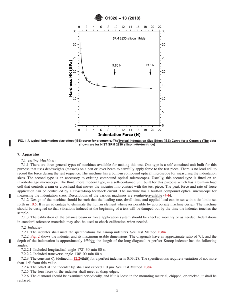
5.6 A full hardness characterization includes measurements over a broad range of indentation forces. Knoop hardness of
ceramics usually decreases with increasing indentation size or indentation force such as that shown in Fig. 1. The trend is known
as the indentation size effect (ISE). Hardness approaches a plateau constant hardness at sufficiently large indentation size or forces
(loads). The test forces that are needed to achieve a constant hardness vary with the ceramic. The test force specified in this
standard is intended to be sufficiently large that hardness is either close to or on the plateau, but not so large as to introduce
excessive cracking. A comprehensive characterization of the ISE is recommended but is beyond the scope of this test method which
measures hardness at a single, designated force.
6. Interferences
6.1 Cracking from the indentation tips can interfere with interpretation of the exact tip location. The forces chosen for this test
method are sufficiently low that tip cracking, if it occurs, will cause tiny, rather tight cracks at the indentation tips in advanced
ceramics. Such cracks will have a negligible interference on measurements of the long diagonal length (2) (unlike Vickers
indentations in ceramics).
6.2 Cracking or spalling from the sides of the Knoop impression may also occur, possibly in a time-dependent manner (minutes
or hours) after the impression is made. Small amounts of such lateral cracking have little or no influence upon measured hardness,
provided that the tip impressions are still readable and the tips are not dislodged (2).
6.3 Porosity (either on or just below the surface) may interfere with measuring Knoop hardness, especially if the indentation
falls directly onto a large pore or if the indentation tip falls in a pore.
6.4 At higher magnifications in the optical microscope, it may be difficult to obtain a sharp contrast between the indentation tip
and the polished surface of some advanced ceramics. This may be overcome by careful adjustment of the lighting as discussed in
Test Method E384 and Refs (2, 3).
The boldface numbers in parentheses refer to the list of references at the end of this test method.
Standard Reference Materials Program (NIST) 100 Bureau Drive, Stop 2300 Gaithersburg, MD 20899-2300.
C1326 − 13 (2018)
FIG. 1 A typical indentation size effect (ISE) curve for a ceramic. TheTypical Indentation Size Effect (ISE) Curve for a Ceramic (The data
shown are for NIST SRM 2830 silicon nitride.nitride)
7. Apparatus
7.1 Testing Machines:
7.1.1 There are three general types of machines available for making this test. One type is a self-contained unit built for this
purpose that uses deadweights (masses) on a pan or lever beam to carefully apply force to the test piece. There is no load cell to
record the force during the test sequence. The machine has a built-in compound optical microscope for measuring the indentation
sizes. The second type is an accessory to existing compound optical microscopes. Usually, this second type is fitted on an
inverted-stage microscope. The third, more modern type, is a self-contained unit built for this purpose which has a built-in load
cell that controls a ram or crosshead that moves the indenter into contact with the test piece. The peak force and rate of force
application can be controlled by a closed-loop feedback circuit. The machine has a built-in compound optical microscope for
measuring the indentation sizes. Descriptions of the various machines are available.available (4-6).
7.1.2 Design of the machine should be such that the loading rate, dwell time, and applied load can be set within the limits set
forth in 10.5. It is an advantage to eliminate the human element whenever possible by appropriate machine design. The machine
should be designed so that vibrations induced at the beginning of a test will be damped out by the time the indenter touches the
sample.
7.1.3 The calibration of the balance beam or force application system should be checked monthly or as needed. Indentations
in standard reference materials may also be used to check calibration when needed.
7.2 Indenter:
7.2.1 The indenter shall meet the specifications for Knoop indenters. See Test Method E384.
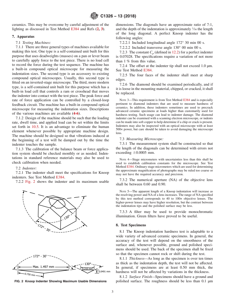
7.2.2 Fig. 2 shows the indenter and its maximum usable dimensions. The diagonals have an approximate ratio of 7:1, and the
depth of the indentation is approximately 1/30 ⁄30 the length of the long diagonal. A perfect Knoop indenter has the following
angles:
7.2.2.1 Included longitudinal angle 172° 30 min 00 s.
7.2.2.2 Included transverse angle 130° 00 min 00 s.
7.2.3 The constant C (defined in 12.212.2)) for a perfect indenter is 0.07028. The specifications require a variation of not more
p
than 1 % from this value.
7.2.4 The offset at the indenter tip shall not exceed 1.0 μm. See Test Method E384.
7.2.5 The four faces of the indenter shall meet at sharp edges.
7.2.6 The diamond should be examined periodically, and if it is loose in the mounting material, chipped, or cracked, it shall be
replaced.
C1326 − 13 (2018)
FIG. 2 Knoop Indenter Showing Maximum Usable Dimensions
NOTE 3—This requirement is from Test Method E384 and is especially pertinent to diamond indenters that are used to measure hardness of ceramics.
In addition, these indenters sometimes are used to precrack advanced ceramic specimens at loads higher than customarily used for hardness testing. Such
usage can lead to indenter damage. The diamond indenter can be examined with a scanning electron microscope, or indents can be made into soft copper
to help determine if a chip or crack is present. Indenters may also be inspected with an optical microscope with at least 500X500× power, but care should
be taken to avoid damaging the microscope lens.
7.3 Measuring Microscope:
7.3.1 The measurement system shall be constructed so that the length of the diagonals can be determined with errors not
exceeding 60.0005 mm.
NOTE 4—Stage micrometers with uncertainties less than this shall be used to establish calibration constants for the microscope. See Test Method E384.
Ordinary stage micrometers which are used for determining the approximate magnification of photographs may be ruled too coarse or may not have the
required accuracy and precision.
7.3.2 The numerical aperture (NA) of the objective lens shall be between 0.60 and 0.90.
NOTE 5—The apparent length of a Knoop indentation will increase as the resolving power and NA of a lens increases. The range of NA specified by
this test method corresponds to 40 to 100× objective lenses. The higher power higher-power lenses may have higher resolution, but the contrast between
the indentation tips and the polished surface may be less.
7.3.3 A filter may be used to provide monochromatic illumination. Green filters have proved to be useful.
8. Test Specimens
8.1 The Knoop indentation hardness test is adaptable to a wide variety of advanced ceramic specimens. In general, the accuracy
of the test will depend on the smoothness of the surface and, whenever poss
...
Questions, Comments and Discussion
Ask us and Technical Secretary will try to provide an answer. You can facilitate discussion about the standard in here.