


ASTM E458-08(2015)
(Test Method)Standard Test Method for Heat of Ablation
Standard Test Method for Heat of Ablation
SIGNIFICANCE AND USE
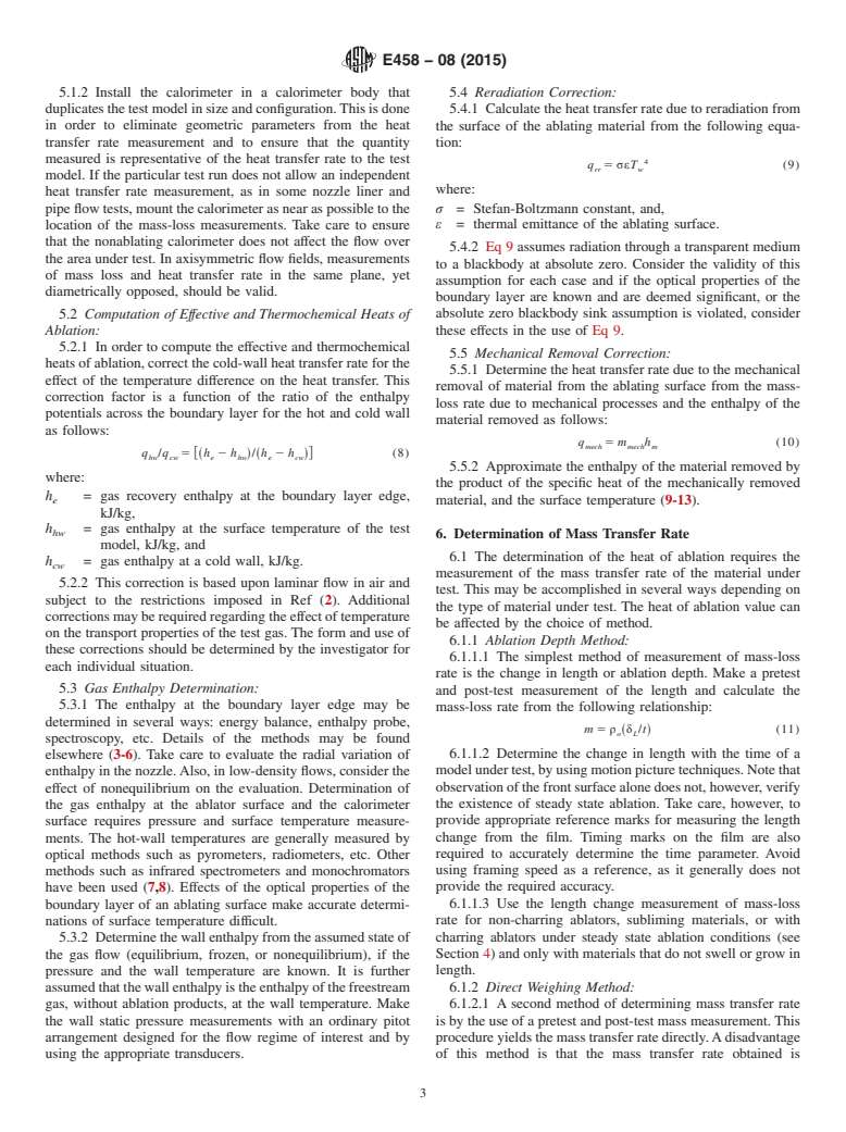
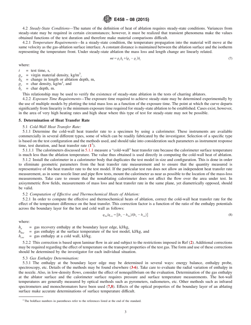
4.1 General—The heat of ablation provides a measure of the ability of a material to serve as a heat protection element in a severe thermal environment. The parameter is a function of both the material and the environment to which it is subjected. It is therefore required that laboratory measurements of heat of ablation simulate the service environment as closely as possible. Some of the parameters affecting the heat of ablation are pressure, gas composition, heat transfer rate, mode of heat transfer, and gas enthalpy. As laboratory duplication of all parameters is usually difficult, the user of the data should consider the differences between the service and the test environments. Screening tests of various materials under simulated use conditions may be quite valuable even if all the service environmental parameters are not available. These tests are useful in material selection studies, materials development work, and many other areas.
4.2 Steady-State Conditions—The nature of the definition of heat of ablation requires steady-state conditions. Variances from steady-state may be required in certain circumstances; however, it must be realized that transient phenomena make the values obtained functions of the test duration and therefore make material comparisons difficult.
4.2.1 Temperature Requirements—In a steady-state condition, the temperature propagation into the material will move at the same velocity as the gas-ablation surface interface. A constant distance is maintained between the ablation surface and the isotherm representing the temperature front. Under steady-state ablation the mass loss and length change are linearly related.
where:
t = test time, s, ρo = virgin material density, kg/m3, δL = change in length or ablation depth, m, ρc = char density, kg/m3, and δc = char depth, m. This relationship may be used to verify the existence of steady-state ablation in the tests of charring ablators.
4.2.2 Exposure T...
SCOPE
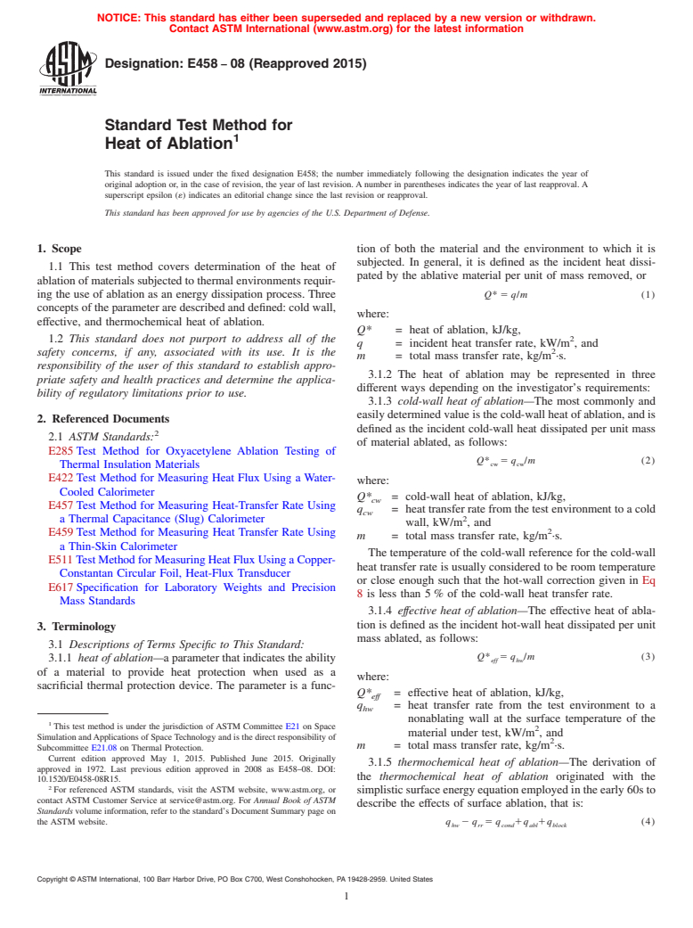
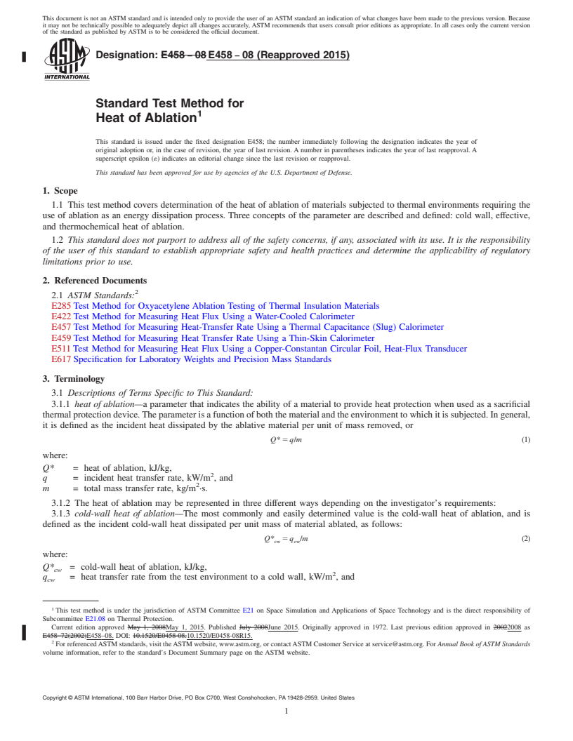
1.1 This test method covers determination of the heat of ablation of materials subjected to thermal environments requiring the use of ablation as an energy dissipation process. Three concepts of the parameter are described and defined: cold wall, effective, and thermochemical heat of ablation.
1.2 This standard does not purport to address all of the safety concerns, if any, associated with its use. It is the responsibility of the user of this standard to establish appropriate safety and health practices and determine the applicability of regulatory limitations prior to use.
General Information
Buy Standard
Standards Content (Sample)
NOTICE: This standard has either been superseded and replaced by a new version or withdrawn.
Contact ASTM International (www.astm.org) for the latest information
Designation: E458 − 08 (Reapproved 2015)
Standard Test Method for
Heat of Ablation
This standard is issued under the fixed designation E458; the number immediately following the designation indicates the year of
original adoption or, in the case of revision, the year of last revision.Anumber in parentheses indicates the year of last reapproval.A
superscript epsilon (´) indicates an editorial change since the last revision or reapproval.
This standard has been approved for use by agencies of the U.S. Department of Defense.
1. Scope tion of both the material and the environment to which it is
subjected. In general, it is defined as the incident heat dissi-
1.1 This test method covers determination of the heat of
pated by the ablative material per unit of mass removed, or
ablationofmaterialssubjectedtothermalenvironmentsrequir-
ing the use of ablation as an energy dissipation process. Three Q* 5 q/m (1)
conceptsoftheparameteraredescribedanddefined:coldwall,
where:
effective, and thermochemical heat of ablation.
Q* = heat of ablation, kJ/kg,
1.2 This standard does not purport to address all of the
q = incident heat transfer rate, kW/m , and
safety concerns, if any, associated with its use. It is the
m = total mass transfer rate, kg/m ·s.
responsibility of the user of this standard to establish appro-
3.1.2 The heat of ablation may be represented in three
priate safety and health practices and determine the applica-
different ways depending on the investigator’s requirements:
bility of regulatory limitations prior to use.
3.1.3 cold-wall heat of ablation—The most commonly and
easilydeterminedvalueisthecold-wallheatofablation,andis
2. Referenced Documents
defined as the incident cold-wall heat dissipated per unit mass
2.1 ASTM Standards:
of material ablated, as follows:
E285Test Method for Oxyacetylene Ablation Testing of
Q* 5 q /m (2)
cw cw
Thermal Insulation Materials
E422Test Method for Measuring Heat Flux Using a Water-
where:
Cooled Calorimeter
Q* = cold-wall heat of ablation, kJ/kg,
cw
E457Test Method for Measuring Heat-Transfer Rate Using
q = heattransferratefromthetestenvironmenttoacold
cw
a Thermal Capacitance (Slug) Calorimeter
wall, kW/m , and
E459Test Method for Measuring Heat Transfer Rate Using
m = total mass transfer rate, kg/m ·s.
a Thin-Skin Calorimeter
The temperature of the cold-wall reference for the cold-wall
E511TestMethodforMeasuringHeatFluxUsingaCopper-
heat transfer rate is usually considered to be room temperature
Constantan Circular Foil, Heat-Flux Transducer
or close enough such that the hot-wall correction given in Eq
E617Specification for Laboratory Weights and Precision
8 is less than 5% of the cold-wall heat transfer rate.
Mass Standards
3.1.4 effective heat of ablation—The effective heat of abla-
tion is defined as the incident hot-wall heat dissipated per unit
3. Terminology
mass ablated, as follows:
3.1 Descriptions of Terms Specific to This Standard:
Q* 5 q /m (3)
3.1.1 heatofablation—aparameterthatindicatestheability eff hw
of a material to provide heat protection when used as a
where:
sacrificial thermal protection device. The parameter is a func-
Q* = effective heat of ablation, kJ/kg,
eff
q = heat transfer rate from the test environment to a
hw
nonablating wall at the surface temperature of the
This test method is under the jurisdiction of ASTM Committee E21 on Space
material under test, kW/m , and
Simulation andApplications of SpaceTechnology and is the direct responsibility of
m = total mass transfer rate, kg/m ·s.
Subcommittee E21.08 on Thermal Protection.
Current edition approved May 1, 2015. Published June 2015. Originally
3.1.5 thermochemical heat of ablation—The derivation of
approved in 1972. Last previous edition approved in 2008 as E458–08. DOI:
the thermochemical heat of ablation originated with the
10.1520/E0458-08R15.
For referenced ASTM standards, visit the ASTM website, www.astm.org, or
simplisticsurfaceenergyequationemployedintheearly60sto
contact ASTM Customer Service at service@astm.org. For Annual Book of ASTM
describe the effects of surface ablation, that is:
Standards volume information, refer to the standard’s Document Summary page on
the ASTM website. q 2 q 5 q 1q 1q (4)
hw rr cond abl block
Copyright © ASTM International, 100 Barr Harbor Drive, PO Box C700, West Conshohocken, PA 19428-2959. United States
E458 − 08 (2015)
where: pressure, gas composition, heat transfer rate, mode of heat
transfer, and gas enthalpy. As laboratory duplication of all
q = energy re-radiated from the heated surface, kW/m ,
rr
parameters is usually difficult, the user of the data should
q = net energy conducted into the solid during steady-
cond
consider the differences between the service and the test
state ablation = mc (T −T ), kW/m ,
p w o
environments.Screeningtestsofvariousmaterialsundersimu-
q = energy absorbed by surface ablation which, in
abl
simple terms, can be represented by m∆ H,kW/m , lated use conditions may be quite valuable even if all the
v
q = energy dissipated (blockage) by transpiration of serviceenvironmentalparametersarenotavailable.Thesetests
block
ablation products into the boundary layer, which, in
are useful in material selection studies, materials development
simple terms, can be represented by mη(h −h ), work, and many other areas.
r w
kW/m ,
4.2 Steady-StateConditions—Thenatureofthedefinitionof
T = absolutesurfacetemperatureofablatingmaterial,K,
w
heat of ablation requires steady-state conditions. Variances
c = specific heat at constant pressure of ablating
p
from steady-state may be required in certain circumstances;
material, kJ/kg·K,
however,itmustberealizedthattransientphenomenamakethe
T = initial surface temperature of ablating material, K,
o
values obtained functions of the test duration and therefore
∆H = an effective heat of vaporization, kJ/kg,
v
make material comparisons difficult.
η = a transpiration coefficient,
4.2.1 Temperature Requirements—In a steady-state
h = gas recovery enthalpy, kJ/kg, and
r
condition, the temperature propagation into the material will
h = the wall enthalpy, kJ/kg.
w
moveatthesamevelocityasthegas-ablationsurfaceinterface.
Aconstant distance is maintained between the ablation surface
Using the definitions above, Eq 4 can be rewritten as:
and the isotherm representing the temperature front. Under
q 2 q 5 mc T 2 T 1m∆H 1mη h 2 h (5)
~ ! ~ !
steady-state ablation the mass loss and length change are
hw rr p w o v r w
linearly related.
where it should be apparent that the definition of the ther-
mt 5 ρ δ 1~ρ 2 ρ !δ (7)
mochemical heat of ablation is obtained by dividing Eq 4 by
o L o c c
m, where it is understood that m is a steady-state ablation
where:
rate. The result is:
t = test time, s,
Q* 5 q 2 q /m 5 c T 2 T 1∆H 1η h 2 h (6)
~ ! ~ ! ~ ! 3
tc hw rr p w o v r w
ρ = virgin material density, kg/m ,
o
δ = change in length or ablation depth, m,
As seen from Eq 6, definition of the thermochemical heat
L
ρ = char density, kg/m , and
of ablation requires an ability to measure the cold-wall heat
c
δ = char depth, m.
flux, an ability to define the recovery enthalpy, an ability to c
measure the surface temperature, knowledge of the total
This relationship may be used to verify the existence of
hemispherical emittance (at the temperature and state of the steady-state ablation in the tests of charring ablators.
ablating surface), and the ability to determine the steady- 4.2.2 Exposure Time Requirements—The exposure time re-
state mass loss rate. Assuming these parameters can be mea- quired to achieve steady-state may be determined experimen-
sured (or estimated), the right hand side of Eq 6 implies that tally by the use of multiple models by plotting the total mass
the thermochemical heat of ablation is a linear function of loss as a function of the exposure time. The point at which the
the enthalpy difference across the boundary layer, that is, curve departs significantly from linearity is the minimum
(h −h ). Consequently, a plot of Q* (determined from sev- exposure time required for steady-state ablation to be estab-
r w tc
eral tests at different conditions) versus (h − h ) should lished. Cases exist, however, in the area of very high heating
r w
allow a linear fit of the data where the slope of the fit is in- ratesandhighshearwherethistypeoftestforsteady-statemay
terpreted as η, the transpiration coefficient, and the not be possible.
y-intercept is interpreted as c ∆ T + ∆H . If the specific heat
p v
5. Determination of Heat Transfer Rate
of the material is known, the curve fit allows the effective
5.1 Cold-Wall Heat Transfer Rate:
heat of vaporization to be empirically derived.
5.1.1 Determine the cold-wall heat transfer rate to a speci-
3.2 The three heat of ablation values described in 3.1.2
men by using a calorimeter. These instruments are available
require two basic determinations: the heat transfer rate and the
commercially in several different types, some of which can be
mass transfer rate. These two quantities then assume various
readily fabricated by the investigator. Selection of a specific
forms depending on the particular heat of ablation value being
type is based on the test configuration and the methods used,
determined.
and should take into consideration such parameters as instru-
ment response time, test duration, and heat transfer rate (1 ).
4. Significance and Use
5.1.1.1 Thecalorimetersdiscussedin5.1.1measurea“cold-
4.1 General—Theheatofablationprovidesameasureofthe
wall” heat transfer rate because the calorimeter surface tem-
ability of a material to serve as a heat protection element in a
perature is much less than the ablation temperature. The value
severe thermal environment. The parameter is a function of
thus obtained is used directly in computing the cold-wall heat
both the material and the environment to which it is subjected.
of ablation.
Itisthereforerequiredthatlaboratorymeasurementsofheatof
ablation simulate the service environment as closely as pos-
The boldface numbers in parentheses refer to the references listed at the end of
sible. Some of the parameters affecting the heat of ablation are the standard.
E458 − 08 (2015)
5.1.2 Install the calorimeter in a calorimeter body that 5.4 Reradiation Correction:
duplicatesthetestmodelinsizeandconfiguration.Thisisdone 5.4.1 Calculatetheheattransferrateduetoreradiationfrom
in order to eliminate geometric parameters from the heat the surface of the ablating material from the following equa-
transfer rate measurement and to ensure that the quantity tion:
measured is representative of the heat transfer rate to the test
q 5σεT (9)
rr w
model. If the particular test run does not allow an independent
where:
heat transfer rate measurement, as in some nozzle liner and
pipeflowtests,mountthecalorimeterasnearaspossibletothe σ = Stefan-Boltzmann constant, and,
ε = thermal emittance of the ablating surface.
location of the mass-loss measurements. Take care to ensure
that the nonablating calorimeter does not affect the flow over
5.4.2 Eq 9 assumes radiation through a transparent medium
the area under test. In axisymmetric flow fields, measurements
to a blackbody at absolute zero. Consider the validity of this
of mass loss and heat transfer rate in the same plane, yet
assumption for each case and if the optical properties of the
diametrically opposed, should be valid.
boundary layer are known and are deemed significant, or the
5.2 Computation of Effective and Thermochemical Heats of absolute zero blackbody sink assumption is violated, consider
Ablation: these effects in the use of Eq 9.
5.2.1 In order to compute the effective and thermochemical
5.5 Mechanical Removal Correction:
heatsofablation,correctthecold-wallheattransferrateforthe
5.5.1 Determine the heat transfer rate due to the mechanical
effect of the temperature difference on the heat transfer. This
removal of material from the ablating surface from the mass-
correction factor is a function of the ratio of the enthalpy
loss rate due to mechanical processes and the enthalpy of the
potentials across the boundary layer for the hot and cold wall
material removed as follows:
as follows:
q 5 m h (10)
mech mech m
q /q 5 @~h 2 h !/~h 2 h !# (8)
hw cw e hw e cw
5.5.2 Approximate the enthalpy of the material removed by
where:
the product of the specific heat of the mechanically removed
h = gas recovery enthalpy at the boundary layer edge,
e material, and the surface temperature (9-13).
kJ/kg,
h = gas enthalpy at the surface temperature of the test
hw
6. Determination of Mass Transfer Rate
model, kJ/kg, and
6.1 The determination of the heat of ablation requires the
h = gas enthalpy at a cold wall, kJ/kg.
cw
measurement of the mass transfer rate of the material under
5.2.2 This correction is based upon laminar flow in air and
test. This may be accomplished in several ways depending on
subject to the restrictions imposed in Ref (2). Additional
the type of material under test. The heat of ablation value can
correctionsmayberequiredregardingtheeffectoftemperature
be affected by the choice of method.
on the transport properties of the test gas.The form and use of
6.1.1 Ablation Depth Method:
these corrections should be determined by the investigator for
6.1.1.1 The simplest method of measurement of mass-loss
each individual situation.
rate is the change in length or ablation depth. Make a pretest
5.3 Gas Enthalpy Determination:
and post-test measurement of the length and calculate the
5.3.1 The enthalpy at the boundary layer edge may be
mass-loss rate from the following relationship:
determined in several ways: energy balance, enthalpy probe,
m 5 ρ ~δ /t! (11)
o L
spectroscopy, etc. Details of the methods may be found
6.1.1.2 Determine the change in length with the time of a
elsewhere (3-6). Take care to evaluate the radial variation of
modelundertest,byusingmotionpicturetechniques.Notethat
enthalpyinthenozzle.Also,inlow-densityflows,considerthe
observationofthefrontsurfacealonedoesnot,however,verify
effect of nonequilibrium on the evaluation. Determination of
the existence of steady state ablation. Take care, however, to
the gas enthalpy at the ablator surface and the calorimeter
provide appropriate reference marks for measuring the length
surface requires pressure and surface temperature measure-
change from the film. Timing marks on the film are also
ments. The hot-wall temperatures are generally measured by
required to accurately determine the time parameter. Avoid
optical methods such as pyrometers, radiometers, etc. Other
using framing speed as a reference, as it generally does not
methods such as infrared spectrometers and monochromators
have been used (7,8). Effects of the optical properties of the provide the required accuracy.
...
This document is not an ASTM standard and is intended only to provide the user of an ASTM standard an indication of what changes have been made to the previous version. Because
it may not be technically possible to adequately depict all changes accurately, ASTM recommends that users consult prior editions as appropriate. In all cases only the current version
of the standard as published by ASTM is to be considered the official document.
Designation: E458 − 08 E458 − 08 (Reapproved 2015)
Standard Test Method for
Heat of Ablation
This standard is issued under the fixed designation E458; the number immediately following the designation indicates the year of
original adoption or, in the case of revision, the year of last revision. A number in parentheses indicates the year of last reapproval. A
superscript epsilon (´) indicates an editorial change since the last revision or reapproval.
This standard has been approved for use by agencies of the U.S. Department of Defense.
1. Scope
1.1 This test method covers determination of the heat of ablation of materials subjected to thermal environments requiring the
use of ablation as an energy dissipation process. Three concepts of the parameter are described and defined: cold wall, effective,
and thermochemical heat of ablation.
1.2 This standard does not purport to address all of the safety concerns, if any, associated with its use. It is the responsibility
of the user of this standard to establish appropriate safety and health practices and determine the applicability of regulatory
limitations prior to use.
2. Referenced Documents
2.1 ASTM Standards:
E285 Test Method for Oxyacetylene Ablation Testing of Thermal Insulation Materials
E422 Test Method for Measuring Heat Flux Using a Water-Cooled Calorimeter
E457 Test Method for Measuring Heat-Transfer Rate Using a Thermal Capacitance (Slug) Calorimeter
E459 Test Method for Measuring Heat Transfer Rate Using a Thin-Skin Calorimeter
E511 Test Method for Measuring Heat Flux Using a Copper-Constantan Circular Foil, Heat-Flux Transducer
E617 Specification for Laboratory Weights and Precision Mass Standards
3. Terminology
3.1 Descriptions of Terms Specific to This Standard:
3.1.1 heat of ablation—a parameter that indicates the ability of a material to provide heat protection when used as a sacrificial
thermal protection device. The parameter is a function of both the material and the environment to which it is subjected. In general,
it is defined as the incident heat dissipated by the ablative material per unit of mass removed, or
Q*5 q/m (1)
where:
Q* = heat of ablation, kJ/kg,
q = incident heat transfer rate, kW/m , and
m = total mass transfer rate, kg/m ·s.
3.1.2 The heat of ablation may be represented in three different ways depending on the investigator’s requirements:
3.1.3 cold-wall heat of ablation—The most commonly and easily determined value is the cold-wall heat of ablation, and is
defined as the incident cold-wall heat dissipated per unit mass of material ablated, as follows:
Q* 5 q /m (2)
cw cw
where:
Q* = cold-wall heat of ablation, kJ/kg,
cw
q = heat transfer rate from the test environment to a cold wall, kW/m , and
cw
This test method is under the jurisdiction of ASTM Committee E21 on Space Simulation and Applications of Space Technology and is the direct responsibility of
Subcommittee E21.08 on Thermal Protection.
Current edition approved May 1, 2008May 1, 2015. Published July 2008June 2015. Originally approved in 1972. Last previous edition approved in 20022008 as
E458–72(2002)E458–08. DOI: 10.1520/E0458-08.10.1520/E0458-08R15.
For referenced ASTM standards, visit the ASTM website, www.astm.org, or contact ASTM Customer Service at service@astm.org. For Annual Book of ASTM Standards
volume information, refer to the standard’s Document Summary page on the ASTM website.
Copyright © ASTM International, 100 Barr Harbor Drive, PO Box C700, West Conshohocken, PA 19428-2959. United States
E458 − 08 (2015)
m = total mass transfer rate, kg/m ·s.
The temperature of the cold-wall reference for the cold-wall heat transfer rate is usually considered to be room temperature or
close enough such that the hot-wall correction given in Eq 8 is less than 5 % of the cold-wall heat transfer rate.
3.1.4 effective heat of ablation—The effective heat of ablation is defined as the incident hot-wall heat dissipated per unit mass
ablated, as follows:
Q* 5 q /m (3)
eff hw
where:
Q* = effective heat of ablation, kJ/kg,
eff
q = heat transfer rate from the test environment to a nonablating wall at the surface temperature of the material under test,
hw
kW/m , and
m = total mass transfer rate, kg/m ·s.
3.1.5 thermochemical heat of ablation—The derivation of the thermochemical heat of ablation originated with the simplistic
surface energy equation employed in the early 60s to describe the effects of surface ablation, that is:
q 2 q 5 q 1q 1q (4)
hw rr cond abl block
where:
q = energy re-radiated from the heated surface, kW/m ,
rr
q = net energy conducted into the solid during steady-state ablation = mc (T − T ), kW/m ,
cond p w o
q = energy absorbed by surface ablation which, in simple terms, can be represented by mΔ H , kW/m ,
abl v
q = energy dissipated (blockage) by transpiration of ablation products into the boundary layer, which, in simple terms, can
block
be represented by mη(h − h ), kW/m ,
r w
T = absolute surface temperature of ablating material, K,
w
c = specific heat at constant pressure of ablating material, kJ/kg·K,
p
T = initial surface temperature of ablating material, K,
o
ΔH = an effective heat of vaporization, kJ/kg,
v
η = a transpiration coefficient,
h = gas recovery enthalpy, kJ/kg, and
r
h = the wall enthalpy, kJ/kg.
w
Using the definitions above, Eq 4 can be rewritten as:
q 2 q 5 mc T 2 T 1mΔH 1mη h 2 h (5)
~ ! ~ !
hw rr p w o v r w
where it should be apparent that the definition of the thermochemical heat of ablation is obtained by dividing Eq 4 by m,
where it is understood that m is a steady-state ablation rate. The result is:
Q* 5 ~q 2 q !/m 5 c ~T 2 T !1ΔH 1η~h 2 h ! (6)
tc hw rr p w o v r w
As seen from Eq 6, definition of the thermochemical heat of ablation requires an ability to measure the cold-wall heat flux,
an ability to define the recovery enthalpy, an ability to measure the surface temperature, knowledge of the total hemispherical
emittance (at the temperature and state of the ablating surface), and the ability to determine the steady-state mass loss rate.
Assuming these parameters can be measured (or estimated), the right hand side of Eq 6 implies that the thermochemical heat
of ablation is a linear function of the enthalpy difference across the boundary layer, that is, (h − h ). Consequently, a plot of
r w
Q* (determined from several tests at different conditions) versus (h − h ) should allow a linear fit of the data where the
tc r w
slope of the fit is interpreted as η, the transpiration coefficient, and the y-intercept is interpreted as c Δ T + ΔH . If the specific
p v
heat of the material is known, the curve fit allows the effective heat of vaporization to be empirically derived.
3.2 The three heat of ablation values described in 3.1.2 require two basic determinations: the heat transfer rate and the mass
transfer rate. These two quantities then assume various forms depending on the particular heat of ablation value being determined.
4. Significance and Use
4.1 General—The heat of ablation provides a measure of the ability of a material to serve as a heat protection element in a severe
thermal environment. The parameter is a function of both the material and the environment to which it is subjected. It is therefore
required that laboratory measurements of heat of ablation simulate the service environment as closely as possible. Some of the
parameters affecting the heat of ablation are pressure, gas composition, heat transfer rate, mode of heat transfer, and gas enthalpy.
As laboratory duplication of all parameters is usually difficult, the user of the data should consider the differences between the
service and the test environments. Screening tests of various materials under simulated use conditions may be quite valuable even
if all the service environmental parameters are not available. These tests are useful in material selection studies, materials
development work, and many other areas.
E458 − 08 (2015)
4.2 Steady-State Conditions—The nature of the definition of heat of ablation requires steady-state conditions. Variances from
steady-state may be required in certain circumstances; however, it must be realized that transient phenomena make the values
obtained functions of the test duration and therefore make material comparisons difficult.
4.2.1 Temperature Requirements—In a steady-state condition, the temperature propagation into the material will move at the
same velocity as the gas-ablation surface interface. A constant distance is maintained between the ablation surface and the isotherm
representing the temperature front. Under steady-state ablation the mass loss and length change are linearly related.
mt 5 ρ δ 1 ρ 2 ρ δ (7)
~ !
o L o c c
where:
t = test time, s,
ρ = virgin material density, kg/m ,
o
δ = change in length or ablation depth, m,
L
ρ = char density, kg/m , and
c
δ = char depth, m.
c
This relationship may be used to verify the existence of steady-state ablation in the tests of charring ablators.
4.2.2 Exposure Time Requirements—The exposure time required to achieve steady-state may be determined experimentally by
the use of multiple models by plotting the total mass loss as a function of the exposure time. The point at which the curve departs
significantly from linearity is the minimum exposure time required for steady-state ablation to be established. Cases exist, however,
in the area of very high heating rates and high shear where this type of test for steady-state may not be possible.
5. Determination of Heat Transfer Rate
5.1 Cold-Wall Heat Transfer Rate:
5.1.1 Determine the cold-wall heat transfer rate to a specimen by using a calorimeter. These instruments are available
commercially in several different types, some of which can be readily fabricated by the investigator. Selection of a specific type
is based on the test configuration and the methods used, and should take into consideration such parameters as instrument response
time, test duration, and heat transfer rate (1 ).
5.1.1.1 The calorimeters discussed in 5.1.1 measure a “cold-wall” heat transfer rate because the calorimeter surface temperature
is much less than the ablation temperature. The value thus obtained is used directly in computing the cold-wall heat of ablation.
5.1.2 Install the calorimeter in a calorimeter body that duplicates the test model in size and configuration. This is done in order
to eliminate geometric parameters from the heat transfer rate measurement and to ensure that the quantity measured is
representative of the heat transfer rate to the test model. If the particular test run does not allow an independent heat transfer rate
measurement, as in some nozzle liner and pipe flow tests, mount the calorimeter as near as possible to the location of the mass-loss
measurements. Take care to ensure that the nonablating calorimeter does not affect the flow over the area under test. In
axisymmetric flow fields, measurements of mass loss and heat transfer rate in the same plane, yet diametrically opposed, should
be valid.
5.2 Computation of Effective and Thermochemical Heats of Ablation:
5.2.1 In order to compute the effective and thermochemical heats of ablation, correct the cold-wall heat transfer rate for the
effect of the temperature difference on the heat transfer. This correction factor is a function of the ratio of the enthalpy potentials
across the boundary layer for the hot and cold wall as follows:
q /q 5 @~h 2 h !/~h 2 h !# (8)
hw cw e hw e cw
where:
h = gas recovery enthalpy at the boundary layer edge, kJ/kg,
e
h = gas enthalpy at the surface temperature of the test model, kJ/kg, and
hw
h = gas enthalpy at a cold wall, kJ/kg.
cw
5.2.2 This correction is based upon laminar flow in air and subject to the restrictions imposed in Ref (2). Additional corrections
may be required regarding the effect of temperature on the transport properties of the test gas. The form and use of these corrections
should be determined by the investigator for each individual situation.
5.3 Gas Enthalpy Determination:
5.3.1 The enthalpy at the boundary layer edge may be determined in several ways: energy balance, enthalpy probe,
spectroscopy, etc. Details of the methods may be found elsewhere (3-6). Take care to evaluate the radial variation of enthalpy in
the nozzle. Also, in low-density flows, consider the effect of nonequilibrium on the evaluation. Determination of the gas enthalpy
at the ablator surface and the calorimeter surface requires pressure and surface temperature measurements. The hot-wall
temperatures are generally measured by optical methods such as pyrometers, radiometers, etc. Other methods such as infrared
spectrometers and monochromators have been used (7,8). Effects of the optical properties of the boundary layer of an ablating
surface make accurate determinations of surface temperature difficult.
The boldface numbers in parentheses refer to the references listed at the end of the standard.
E458 − 08 (2015)
5.3.2 Determine the wall enthalpy from the assumed state of the gas flow (equilibrium, frozen, or nonequilibrium), if the
pressure and the wall temperature are known. It is further assumed that the wall enthalpy is the enthalpy of the freestream gas,
without ablation products, at the wall temperature. Make the wall static pressure measurements with an ordinary pitot arrangement
designed for the flow regime of interest and by using the appropriate transducers.
5.4 Reradiation Correction:
5.4.1 Calculate the heat transfer rate due to reradiation from the surface of the ablating material from the following equation:
q 5 σεT (9)
rr w
where:
σ = Stefan-Boltzmann constant, and,
ε = thermal emittance of the ablating surface.
5.4.2 Eq 9 assumes radiation through a transparent medium to a blackbody at absolute zero. Consider the validity of this
assumption for each case and if the optical properties of the boundary layer are known and are deemed significant, or the absolute
zero blackbody sink assumption is violated, consider these effects in the use of Eq 9.
5.5 Mechanical Removal Correction:
5.5.1 Determine the heat transfer rate due to the mechanical removal of material from the ablating surface from the mass-loss
rate due to mechanical processes and the enthalpy of the material removed as follows:
q 5 m h (10)
mech mech m
5.5.2 Approximate the enthalpy of the material removed by the product of the specific heat of the mechanically
...
Questions, Comments and Discussion
Ask us and Technical Secretary will try to provide an answer. You can facilitate discussion about the standard in here.