

ASTM C76-22a
(Specification)Standard Specification for Reinforced Concrete Culvert, Storm Drain, and Sewer Pipe
General Information
- Abstract
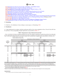
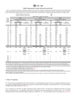
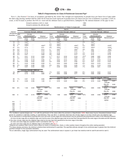
ABSTRACT
This specification covers reinforced concrete culvert, storm drain, and sewer pipe. The pipe manufactured with this specification shall be of five classes: Class I, Class II, Class III, Class IV, and Class V. The strength requirements for each class are specified. The reinforced concrete shall consists of: cementitious materials, mineral aggregates, and water. Cementitious materials are the following: cement, ground granulated blast-furnace slag, fly ash, and allowable combinations of cementitious materials. Other materials include: admixtures and blends, steel reinforcement, and synthetic fibers. Design tables and modified of special designs are given. Reinforcements are the following: circumferential reinforcement, longitudinal reinforcement, and joint reinforcement for rubber and non-rubber gasket joints. The physical properties shall conform to the required test for external load crushing strength. The following concrete tests shall be done: compression testing of cylinders, compression testing of cores, absorption test, and equipment test.
SCOPE
1.1 This specification covers reinforced concrete pipe intended to be used for the conveyance of sewage, industrial wastes, and storm water, and for the construction of culverts.
1.2 This specification is the inch-pound companion to Specification C76M; therefore, no SI equivalents are presented in this specification. Reinforced concrete pipe that conform to the requirements of C76M, are acceptable under this Specification C76 unless prohibited by the Owner.
Note 1: This specification is a manufacturing and purchase specification only, and does not include requirements for bedding, backfill, or the relationship between field load condition and the strength classification of pipe. However, experience has shown that the successful performance of this product depends upon the proper selection of the class of pipe, type of bedding and backfill, and care that installation conforms to the construction specifications. The owner of the reinforced concrete pipe specified herein is cautioned that he must correlate the field requirements with the class of pipe specified and provide inspection at the construction site.
Note 2: Attention is called to the specification for reinforced concrete D-load culvert, storm drain, and sewer pipe (Specification C655).
1.3 This international standard was developed in accordance with internationally recognized principles on standardization established in the Decision on Principles for the Development of International Standards, Guides and Recommendations issued by the World Trade Organization Technical Barriers to Trade (TBT) Committee.
- Status
- Published
- Publication Date
- 31-Aug-2022
- Technical Committee
- C13 - Concrete Pipe
- Drafting Committee
- C13.02 - Reinforced Sewer and Culvert Pipe
Buy Documents
ASTM C76-22a - Standard Specification for Reinforced Concrete Culvert, Storm Drain, and Sewer Pipe
REDLINE ASTM C76-22a - Standard Specification for Reinforced Concrete Culvert, Storm Drain, and Sewer Pipe
Overview
ASTM C76-22a: Standard Specification for Reinforced Concrete Culvert, Storm Drain, and Sewer Pipe is a widely recognized standard published by ASTM International. This specification establishes requirements for reinforced concrete pipe designed for the conveyance of sewage, industrial waste, stormwater, and for the construction of culverts. It encompasses five distinct classes of pipe-Class I, II, III, IV, and V-each with specific strength and reinforcement requirements. ASTM C76-22a is used globally by agencies, engineers, contractors, and manufacturers to ensure reliable and consistent performance of reinforced concrete pipe in various infrastructural applications.
Key Topics
Scope and Purpose
ASTM C76-22a covers the inch-pound specification for reinforced concrete pipe, addressing physical properties, materials, manufacturing methods, and acceptance criteria for the product. The standard is intended for use in manufacturing and procurement and does not include requirements for installation, bedding, or backfill.Pipe Classes and Strength
- Five pipe classes (I–V) are defined, each with prescribed strength requirements verified through load testing (such as the three-edge bearing test).
- Each class is designed for specific load and installation conditions, supporting a wide range of project needs.
- Design tables outline the necessary wall thickness, diameter, minimum compressive strength, and reinforcement required for each class.
Materials
- Cementitious materials include portland cement, blended cements, ground granulated blast furnace slag, fly ash, and permissible combinations.
- Aggregates conform to ASTM’s standard specifications (C33/C33M).
- Admixtures (air-entraining, chemical) and synthetic fibers are permitted in accordance with relevant ASTM standards.
- Steel reinforcement is required, meeting standards for wire, welded wire, and deformed or plain bars.
Design and Reinforcement
- Circumferential and longitudinal reinforcement methods are specified to ensure structural integrity.
- Joint reinforcement is detailed for both rubber and non-rubber gasket joints.
- Modified or special designs are allowable with owner approval, provided they meet or exceed standard performance requirements.
Testing and Acceptance
- Pipes must pass load/crushing strength, absorption, and compression tests.
- Basis of acceptance can be plant load-bearing tests or material testing and visual inspection.
- Pipes are considered acceptable upon demonstrated compliance with all required specifications.
Applications
ASTM C76-22a reinforced concrete pipes are used in a variety of critical infrastructure and civil engineering projects, including:
- Culverts-Providing durable drainage under roadways, railways, and embankments.
- Storm drains-Managing urban runoff and mitigating flood risks in municipal drainage networks.
- Sanitary and industrial sewers-Transporting wastewater safely and efficiently.
- Infrastructure projects-Widely specified for public works, DOT projects, utility installations, and private developments where durability, high load-capacity, and longevity are essential.
Using pipe meeting this ASTM standard ensures product reliability, compliance with agency requirements, and compatibility with other standardized components.
Related Standards
When specifying or installing reinforced concrete pipe, consider these key related ASTM standards:
- ASTM C76M: Metric equivalent of ASTM C76-22a.
- ASTM C655: Reinforced concrete D-load culvert, storm drain, and sewer pipe specification.
- ASTM C443: Joints for concrete pipe and manholes using rubber gaskets.
- ASTM C33/C33M: Specification for concrete aggregates.
- ASTM C150/C150M, C595/C595M: Specifications for Portland and blended cements.
- ASTM C497: Test methods for concrete pipe and related products.
- ASTM C1602/C1602M: Specification for mixing water used in concrete production.
Reference to these standards ensures materials, joints, and design elements are consistent and meet recognized industry benchmarks for performance, safety, and constructibility.
Keywords: ASTM C76-22a, reinforced concrete pipe, culvert pipe, storm drain pipe, sewer pipe specification, pipe strength classes, ASTM standards, concrete pipe design, civil engineering, drainage infrastructure, pipe installation standards.
Relations
- Effective Date
- 15-Apr-2024
- Effective Date
- 01-Feb-2024
- Effective Date
- 01-Jan-2024
- Effective Date
- 01-Dec-2019
- Effective Date
- 01-Oct-2019
- Effective Date
- 01-Sep-2019
- Effective Date
- 15-Jul-2019
- Effective Date
- 15-Jul-2019
- Effective Date
- 01-Jul-2019
- Effective Date
- 01-Jul-2019
- Effective Date
- 01-Jul-2019
- Refers
ASTM C309-19 - Standard Specification for Liquid Membrane-Forming Compounds for Curing Concrete - Effective Date
- 15-Jun-2019
- Effective Date
- 01-May-2019
- Effective Date
- 01-Apr-2019
- Effective Date
- 01-Jan-2019
Buy Documents
ASTM C76-22a - Standard Specification for Reinforced Concrete Culvert, Storm Drain, and Sewer Pipe
REDLINE ASTM C76-22a - Standard Specification for Reinforced Concrete Culvert, Storm Drain, and Sewer Pipe
Get Certified
Connect with accredited certification bodies for this standard

Institut za varilstvo d.o.o. (Welding Institute)
Slovenia's leading welding institute since 1952. ISO 3834, EN 1090, pressure equipment certification, NDT personnel, welder qualification. Only IIW Au
Sponsored listings
Frequently Asked Questions
ASTM C76-22a is a technical specification published by ASTM International. Its full title is "Standard Specification for Reinforced Concrete Culvert, Storm Drain, and Sewer Pipe". This standard covers: ABSTRACT This specification covers reinforced concrete culvert, storm drain, and sewer pipe. The pipe manufactured with this specification shall be of five classes: Class I, Class II, Class III, Class IV, and Class V. The strength requirements for each class are specified. The reinforced concrete shall consists of: cementitious materials, mineral aggregates, and water. Cementitious materials are the following: cement, ground granulated blast-furnace slag, fly ash, and allowable combinations of cementitious materials. Other materials include: admixtures and blends, steel reinforcement, and synthetic fibers. Design tables and modified of special designs are given. Reinforcements are the following: circumferential reinforcement, longitudinal reinforcement, and joint reinforcement for rubber and non-rubber gasket joints. The physical properties shall conform to the required test for external load crushing strength. The following concrete tests shall be done: compression testing of cylinders, compression testing of cores, absorption test, and equipment test. SCOPE 1.1 This specification covers reinforced concrete pipe intended to be used for the conveyance of sewage, industrial wastes, and storm water, and for the construction of culverts. 1.2 This specification is the inch-pound companion to Specification C76M; therefore, no SI equivalents are presented in this specification. Reinforced concrete pipe that conform to the requirements of C76M, are acceptable under this Specification C76 unless prohibited by the Owner. Note 1: This specification is a manufacturing and purchase specification only, and does not include requirements for bedding, backfill, or the relationship between field load condition and the strength classification of pipe. However, experience has shown that the successful performance of this product depends upon the proper selection of the class of pipe, type of bedding and backfill, and care that installation conforms to the construction specifications. The owner of the reinforced concrete pipe specified herein is cautioned that he must correlate the field requirements with the class of pipe specified and provide inspection at the construction site. Note 2: Attention is called to the specification for reinforced concrete D-load culvert, storm drain, and sewer pipe (Specification C655). 1.3 This international standard was developed in accordance with internationally recognized principles on standardization established in the Decision on Principles for the Development of International Standards, Guides and Recommendations issued by the World Trade Organization Technical Barriers to Trade (TBT) Committee.
ABSTRACT This specification covers reinforced concrete culvert, storm drain, and sewer pipe. The pipe manufactured with this specification shall be of five classes: Class I, Class II, Class III, Class IV, and Class V. The strength requirements for each class are specified. The reinforced concrete shall consists of: cementitious materials, mineral aggregates, and water. Cementitious materials are the following: cement, ground granulated blast-furnace slag, fly ash, and allowable combinations of cementitious materials. Other materials include: admixtures and blends, steel reinforcement, and synthetic fibers. Design tables and modified of special designs are given. Reinforcements are the following: circumferential reinforcement, longitudinal reinforcement, and joint reinforcement for rubber and non-rubber gasket joints. The physical properties shall conform to the required test for external load crushing strength. The following concrete tests shall be done: compression testing of cylinders, compression testing of cores, absorption test, and equipment test. SCOPE 1.1 This specification covers reinforced concrete pipe intended to be used for the conveyance of sewage, industrial wastes, and storm water, and for the construction of culverts. 1.2 This specification is the inch-pound companion to Specification C76M; therefore, no SI equivalents are presented in this specification. Reinforced concrete pipe that conform to the requirements of C76M, are acceptable under this Specification C76 unless prohibited by the Owner. Note 1: This specification is a manufacturing and purchase specification only, and does not include requirements for bedding, backfill, or the relationship between field load condition and the strength classification of pipe. However, experience has shown that the successful performance of this product depends upon the proper selection of the class of pipe, type of bedding and backfill, and care that installation conforms to the construction specifications. The owner of the reinforced concrete pipe specified herein is cautioned that he must correlate the field requirements with the class of pipe specified and provide inspection at the construction site. Note 2: Attention is called to the specification for reinforced concrete D-load culvert, storm drain, and sewer pipe (Specification C655). 1.3 This international standard was developed in accordance with internationally recognized principles on standardization established in the Decision on Principles for the Development of International Standards, Guides and Recommendations issued by the World Trade Organization Technical Barriers to Trade (TBT) Committee.
ASTM C76-22a is classified under the following ICS (International Classification for Standards) categories: 23.040.50 - Pipes and fittings of other materials. The ICS classification helps identify the subject area and facilitates finding related standards.
ASTM C76-22a has the following relationships with other standards: It is inter standard links to ASTM A1064/A1064M-24, ASTM C989/C989M-24, ASTM C1628-19(2024), ASTM C76M-19b, ASTM C497-19a, ASTM C990-09(2019), ASTM C1628-19, ASTM C655-19a, ASTM C655-19, ASTM C443-19a, ASTM C76M-19a, ASTM C309-19, ASTM C443-19, ASTM C150/C150M-19, ASTM C497-19. Understanding these relationships helps ensure you are using the most current and applicable version of the standard.
ASTM C76-22a is available in PDF format for immediate download after purchase. The document can be added to your cart and obtained through the secure checkout process. Digital delivery ensures instant access to the complete standard document.
Standards Content (Sample)
This international standard was developed in accordance with internationally recognized principles on standardization established in the Decision on Principles for the
Development of International Standards, Guides and Recommendations issued by the World Trade Organization Technical Barriers to Trade (TBT) Committee.
Designation:C76 −22a
Standard Specification for
Reinforced Concrete Culvert, Storm Drain, and Sewer Pipe
This standard is issued under the fixed designation C76; the number immediately following the designation indicates the year of original
adoption or, in the case of revision, the year of last revision.Anumber in parentheses indicates the year of last reapproval.Asuperscript
epsilon (´) indicates an editorial change since the last revision or reapproval.
This standard has been approved for use by agencies of the U.S. Department of Defense.
1. Scope* A706/A706M Specification for Deformed and Plain Low-
Alloy Steel Bars for Concrete Reinforcement
1.1 This specification covers reinforced concrete pipe in-
A1064/A1064M Specification for Carbon-Steel Wire and
tended to be used for the conveyance of sewage, industrial
Welded Wire Reinforcement, Plain and Deformed, for
wastes, and storm water, and for the construction of culverts.
Concrete
1.2 This specification is the inch-pound companion to
C33/C33M Specification for Concrete Aggregates
Specification C76M; therefore, no SI equivalents are presented
C76M Specification for Reinforced Concrete Culvert, Storm
in this specification. Reinforced concrete pipe that conform to
Drain, and Sewer Pipe (Metric)
the requirements of C76M, are acceptable under this Specifi-
C150/C150M Specification for Portland Cement
cation C76 unless prohibited by the Owner.
C260/C260M Specification for Air-Entraining Admixtures
NOTE 1—This specification is a manufacturing and purchase specifica-
for Concrete
tion only, and does not include requirements for bedding, backfill, or the
C309 Specification for Liquid Membrane-Forming Com-
relationship between field load condition and the strength classification of
pounds for Curing Concrete
pipe. However, experience has shown that the successful performance of
C443 Specification for Joints for Concrete Pipe and
this product depends upon the proper selection of the class of pipe, type
of bedding and backfill, and care that installation conforms to the
Manholes, Using Rubber Gaskets
construction specifications. The owner of the reinforced concrete pipe
C494/C494M Specification for Chemical Admixtures for
specified herein is cautioned that he must correlate the field requirements
Concrete
with the class of pipe specified and provide inspection at the construction
C497 Test Methods for Concrete Pipe, Concrete Box
site.
NOTE 2—Attention is called to the specification for reinforced concrete
Sections, Manhole Sections, or Tile
D-load culvert, storm drain, and sewer pipe (Specification C655).
C595/C595M Specification for Blended Hydraulic Cements
1.3 This international standard was developed in accor-
C618 Specification for Coal Fly Ash and Raw or Calcined
dance with internationally recognized principles on standard-
Natural Pozzolan for Use in Concrete
ization established in the Decision on Principles for the
C655 Specification for Reinforced Concrete D-Load
Development of International Standards, Guides and Recom-
Culvert, Storm Drain, and Sewer Pipe
mendations issued by the World Trade Organization Technical
C822 Terminology Relating to Concrete Pipe and Related
Barriers to Trade (TBT) Committee.
Products
C989/C989M Specification for Slag Cement for Use in
2. Referenced Documents
Concrete and Mortars
C990 Specification for Joints for Concrete Pipe, Manholes,
2.1 ASTM Standards:
A36/A36M Specification for Carbon Structural Steel and Precast Box Sections Using Preformed Flexible Joint
A615/A615M SpecificationforDeformedandPlainCarbon- Sealants
Steel Bars for Concrete Reinforcement C1017/C1017M Specification for Chemical Admixtures for
Use in Producing Flowing Concrete (Withdrawn 2022)
C1116/C1116M Specification for Fiber-Reinforced Concrete
1 C1602/C1602M Specification for Mixing Water Used in the
This specification is under the jurisdiction of ASTM Committee C13 on
Concrete Pipe and is the direct responsibility of Subcommittee C13.02 on
Production of Hydraulic Cement Concrete
Reinforced Sewer and Culvert Pipe.
C1628 Specification for Joints for Concrete Gravity Flow
Current edition approved Sept. 1, 2022. Published September 2022. Originally
Sewer Pipe, Using Rubber Gaskets
approved in 1930. Last previous edition approved in 2022 as C76 - 22. DOI:
10.1520/C0076-22A.
For referenced ASTM standards, visit the ASTM website, www.astm.org, or
contact ASTM Customer Service at service@astm.org. For Annual Book of ASTM
Standards volume information, refer to the standard’s Document Summary page on The last approved version of this historical standard is referenced on
the ASTM website. www.astm.org.
*A Summary of Changes section appears at the end of this standard
Copyright © ASTM International, 100 Barr Harbor Drive, PO Box C700, West Conshohocken, PA 19428-2959. United States
C76−22a
3. Terminology in 6.2, 6.3, 6.5, and 6.6; by an absorption test of the concrete
from the wall of the pipe as required in 11.9; and by visual
3.1 Definitions—Fordefinitionsoftermsrelatingtoconcrete
inspection of the finished pipe to determine its conformance
pipe, see Terminology C822.
with the accepted material requirements and its freedom from
4. Classification defects.
5.1.2 Acceptance on the Basis of Material Tests and Inspec-
4.1 Pipe manufactured in accordance with this specification
tion of Manufactured Pipe for Defects and Imperfections—
shall be of five classes identified as Class I, Class II, Class III,
Class IV, and Class V. The corresponding strength require- Acceptability of the pipe in all diameters and classes produced
ments are prescribed in Tables 1-5. in accordance with 7.2 shall be determined by the results of
such material tests as are required in 6.2, 6.3, 6.5, and 6.6;by
5. Basis of Acceptance
crushingtestsonconcretecoresorcuredconcretecylinders;by
an absorption test of the concrete from the wall of the pipe for
5.1 Unlessotherwisedesignatedbytheowneratthetimeof,
or before placing an order, there are two separate and alterna- each mix design that is used on an order; and by inspection of
tive bases of acceptance. Independent of the method of the finished pipe including amount and placement of reinforce-
acceptance, the pipe shall be designed to meet both the 0.01-in.
ment to determine its conformance with the accepted design
crack and ultimate strength requirements specified in Tables
and its freedom from defects.
1-5.
5.1.3 When agreed upon by the owner and manufacturer,
5.1.1 Acceptance on the Basis of Plant Load-Bearing Tests,
any portion or any combination of the tests itemized in 5.1.1 or
Material Tests, and Inspection of Manufactured Pipe for Visual
5.1.2 may form the basis of acceptance.
Defects and Imperfections—Acceptability of the pipe in all
5.2 Age for Acceptance—Pipe shall be considered ready for
diameters and classes produced in accordance with 7.1 or 7.2
acceptance when it conforms to the requirements as indicated
shall be determined by the results of the three-edge bearing
tests as defined in 11.3.1; by such material tests as are required by the specified tests.
A
TABLE 1 Requirements for Class I Reinforced Concrete Pipe
NOTE 1—See Section 5 for basis of acceptance specified by the owner. The strength test requirements in pounds-force per linear foot of pipe under
the three-edge-bearing method shall be either the D-load (test load expressed in pounds-force per linear foot per foot of diameter) to produce a 0.01-in.
crack, or the D-loads to produce the 0.01-in. crack and the ultimate load as specified below, multiplied by the internal diameter of the pipe in feet.
D-load to produce a 0.01-in. crack 800
D-load to produce the ultimate load 1200
Reinforcement, in. /linear ft of pipe wall
Wall A Wall B
Internal
Concrete Strength, 4000 psi Concrete Strength, 4000 psi
Designated
Circular Circular
Diameter,
Wall B Wall B
Reinforcement Reinforcement
in.
Elliptical Elliptical
Thickness, Thickness,
C C
Reinforcement Reinforcement
Inner Outer Inner Outer
in. in.
Cage Cage Cage Cage
60 5 0.24 0.15 0.27 6 0.21 0.12 0.23
1 1
66 5 ⁄2 0.30 0.18 0.33 6 ⁄2 0.24 0.15 0.27
72 6 0.35 0.21 0.39 7 0.29 0.17 0.32
1 1
78 6 ⁄2 0.40 0.24 0.44 7 ⁄2 0.32 0.19 0.36
84 7 0.45 0.27 0.50 8 0.36 0.21 0.41
1 1
90 7 ⁄2 0.49 0.29 0.54 8 ⁄2 0.41 0.24 0.45
96 8 0.54 0.32 0.60 9 0.45 0.27 0.51
Concrete Strength, 5000 psi
1 1
102 8 ⁄2 0.63 0.38 Inner Circular 0.24 9 ⁄2 0.54 0.32 Inner Circular 0.21
Plus Elliptical 0.38 Plus Elliptical 0.32
108 9 0.68 0.41 Inner Circular 0.27 10 0.60 0.36 Inner Circular 0.24
Plus Elliptical 0.41 Plus Elliptical 0.36
A A
114 . . . . . . . .
A A
120 . . . . . . . .
A A
126 . . . . . . . .
A A
132 . . . . . . . .
A A
138 . . . . . . . .
A A
144 . . . . . . . .
A
For modified or special designs see 7.2 or with the permission of the owner utilize the provisions of Specification C655. Steel areas may be interpolated between those
shown for variations in diameter, loading, or wall thickness. Pipe over 96 in. in diameter shall have two circular cages or an inner circular plus one elliptical cage.
B
As an alternative to configurations requiring both inner and outer circular cages the reinforcement may be positioned and proportioned in either of the following manners:
An inner circular cage plus an elliptical cage such that the area of the elliptical cage shall not be less than that specified for the outer cage in the table and the total area
of the inner circular cage plus the elliptical cage shall not be less than that specified for the inner cage in the table,
An inner and outer cage plus quadrant mats in accordance with Fig. 1,or
An inner and outer cage plus an elliptical cage in accordance with Fig. 2.
C
Elliptical and quadrant steel must be held in place by means of holding rods, chairs, or other positive means throughout the entire casting operation.
C76−22a
A
TABLE 2 Requirements for Class II Reinforced Concrete Pipe
NOTE 1—See Section 5 for basis of acceptance specified by the owner. The strength test requirements in pounds-force per linear foot of pipe under
the three-edge-bearing method shall be either the D-load (test load expressed in pounds-force per linear foot per foot of diameter) to produce a 0.01-in.
crack, or the D-loads to produce the 0.01-in. crack and the ultimate load as specified below, multiplied by the internal diameter of the pipe in feet.
D-load to produce a 0.01-in. crack 1000
D-load to produce the ultimate load 1500
Reinforcement, in. /linear ft of pipe wall
Wall A Wall B Wall C
Internal
Desig- Concrete Strength, 4000 psi Concrete Strength, 4000 psi Concrete Strength, 4000 psi
nated
Circular Circular Circular
Wall Wall Wall
Diameter, B B B
Reinforcement Reinforcement Reinforcement
Thick- Elliptical Thick- Elliptical Thick- Elliptical
in.
C C C
ness, Reinforcement ness, Reinforcement ness, Reinforcement
Inner Outer Inner Outer Inner Outer
in. in. in.
Cage Cage Cage Cage Cage Cage
D D D
3 3
12 1 ⁄4 0.07 . . 2 0.07 . . 2 ⁄4 0.07 . .
7 D 1 D D
15 1 ⁄8 0.07 . . 2 ⁄4 0.07 . . 3 0.07 . .
D D D D D D
1 1
18 2 0.07 . . . 0.07 2 ⁄2 0.07 . . . 0.07 3 ⁄4 0.07 . . . 0.07
D D D D
1 3 1
21 2 ⁄4 0.12 . . . 0.10 2 ⁄4 0.07 . . . 0.07 3 ⁄2 0.07 . . . 0.07
D D D D
1 3
24 2 ⁄2 0.12 . . . 0.11 3 0.07 . . . 0.07 3 ⁄4 0.07 . . . 0.07
D D
5 1
27 2 ⁄8 0.15 . . . 0.12 3 ⁄4 0.12 . . . 0.11 4 0.07 . . . 0.07
D D
3 1 1
30 2 ⁄4 0.15 . . . 0.14 3 ⁄2 0.14 . . . 0.12 4 ⁄4 0.07 . . . 0.07
D D
7 3 1
33 2 ⁄8 0.16 . . . 0.15 3 ⁄4 0.15 . . . 0.12 4 ⁄2 0.07 . . . 0.07
E 3 E
36 3 0.14 0.08 0.15 4 0.12 0.07 0.12 4 ⁄4 0.07 0.07 0.08
1 1 1
42 3 ⁄2 0.16 0.10 0.18 4 ⁄2 0.15 0.09 0.17 5 ⁄4 0.10 0.07 0.11
48 4 0.21 0.12 0.23 5 0.18 0.11 0.20 5 ⁄4 0.14 0.08 0.15
1 1 1
54 4 ⁄2 0.24 0.15 0.27 5 ⁄2 0.21 0.12 0.24 6 ⁄4 0.17 0.10 0.19
60 5 0.30 0.18 0.33 6 0.24 0.15 0.27 6 ⁄4 0.21 0.12 0.24
1 1 1
66 5 ⁄2 0.35 0.21 0.39 6 ⁄2 0.31 0.19 0.34 7 ⁄4 0.24 0.15 0.27
72 6 0.41 0.24 0.45 7 0.35 0.21 0.39 7 ⁄4 0.30 0.18 0.33
1 1 1
78 6 ⁄2 0.45 0.27 0.51 7 ⁄2 0.40 0.24 0.44 8 ⁄4 0.35 0.21 0.39
84 7 0.51 0.31 0.57 8 0.45 0.27 0.51 8 ⁄4 0.41 0.24 0.45
1 1 1
90 7 ⁄2 0.57 0.34 0.63 8 ⁄2 0.51 0.31 0.57 9 ⁄4 0.48 0.29 0.53
96 8 0.62 0.36 0.69 9 0.57 0.34 0.63 9 ⁄4 0.55 0.33 0.60
Concrete Strength, 5000 psi
1 1 1
102 8 ⁄2 0.76 0.45 Inner 0.30 9 ⁄2 0.68 0.41 Inner 0.27 10 ⁄4 0.62 0.36 Inner 0.24
Circular Circular Circular
Plus El- 0.45 Plus El- 0.41 Plus El- 0.36
liptical liptical liptical
108 9 0.85 0.51 Inner 0.34 10 0.76 0.45 Inner 0.30 10 ⁄4 0.70 0.42 Inner 0.27
Circular Circular Circular
Plus El- 0.51 Plus El- 0.45 Plus El- 0.42
liptical liptical liptical
A A A
114 . . . . . . . . . . . .
A A A
120 . . . . . . . . . . . .
A A A
126 . . . . . . . . . . . .
A A A
132 . . . . . . . . . . . .
A A A
138 . . . . . . . . . . . .
A A A
144 . . . . . . . . . . . .
A
For modified or special designs see 7.2 or with the permission of the owner utilize the provisions of Specification C655. Steel areas may be interpolated between those
shown for variations in diameter, loading, or wall thickness. Pipe over 96 in. in diameter shall have two circular cages or an inner circular plus one elliptical cage.
B
As an alternative to configurations requiring both inner and outer circular cages the reinforcement may be positioned and proportioned in either of the following manners:
An inner circular cage plus an elliptical cage such that the area of the elliptical cage shall not be less than that specified for the outer cage in the table and the total area
of the inner circular cage plus the elliptical cage shall not be less than that specified for the inner cage in the table,
An inner and outer cage plus quadrant mats in accordance with Fig. 1,or
An inner and outer cage plus an elliptical cage in accordance with Fig. 2.
C
Elliptical and quadrant steel must be held in place by means of holding rods, chairs, or other positive means throughout the entire casting operation.
D
For these classes and sizes, the minimum practical steel reinforcement is specified. The specified ultimate strength of non-reinforced pipe is greater than the minimum
specified strength for the equivalent diameters.
E
As an alternative, single cage reinforcement may be used. The reinforcement area in square in. per linear foot shall be 0.20 for wall B and 0.16 for wall C.
6. Materials cement conforming to the requirements of Specification C595/
C595M, except that the pozzolan constituent in the Type IP
6.1 Reinforced Concrete—The reinforced concrete shall
portland-pozzolan cement shall be fly ash.
consist of cementitious materials; mineral aggregates;
6.2.2 Slag Cement—Slag cement shall conform to the re-
admixtures, if used; and water in which steel has been
quirementsofGrade100or120ofSpecificationC989/C989M.
embedded in such a manner that the steel and concrete act
together.
6.2.3 Fly Ash—Fly ash shall conform to the requirements of
Class F or Class C of Specification C618.
6.2 Cementitious materials:
6.2.1 Cement—Cementshallconformtotherequirementsof 6.2.4 Allowable Combinations of Cementitious Materials—
Thecombinationofcementitiousmaterialsusedintheconcrete
Specification C150/C150M, or shall be portland blast-furnace
slag cement, portland-limestone cement, or portland-pozzolan shall be one of the following:
C76−22a
A
TABLE 3 Requirements for Class III Reinforced Concrete Pipe
NOTE 1—See Section 5 for basis of acceptance specified by the owner. The strength test requirements in pounds-force per linear foot of pipe under
the three-edge-bearing method shall be either the D-load (test load expressed in pounds-force per linear foot per foot of diameter) to produce a 0.01-in.
crack, or the D-loads to produce the 0.01-in. crack and the ultimate load as specified below, multiplied by the internal diameter of the pipe in feet.
D-load to produce a 0.01-in. crack 1350
D-load to produce the ultimate load 2000
Reinforcement, in. /linear ft of pipe wall
Wall A Wall B Wall C
Internal Concrete Strength, 4000 psi Concrete Strength, 4000 psi Concrete Strength, 4000 psi
Designated
Circular Circular Circular
Wall Wall Wall
Diameter, in. B B B
Reinforcement Reinforcement Reinforcement
Thick- Elliptical Thick- Elliptical Thick- Elliptical
C C C
nesses, Reinforcement nesses, Reinforcement nesses, Reinforcement
Inner Outer Inner Outer Inner Outer
in. in. in.
Cage Cage Cage Cage Cage Cage
D D D
3 3
12 1 ⁄4 0.07 . . 2 0.07 . . 2 ⁄4 0.07 . .
7 D 1 D D
15 1 ⁄8 0.07 . . 2 ⁄4 0.07 . . 3 0.07 . .
D D D D D D
1 1
18 2 0.07 . . . 0.07 2 ⁄2 0.07 . . . 0.07 3 ⁄4 0.07 . . . 0.07
D D D D
1 3 1
21 2 ⁄4 0.14 . . . 0.11 2 ⁄4 0.07 . . . 0.07 3 ⁄2 0.07 . . . 0.07
D D D
1 3
24 2 ⁄2 0.17 . . . 0.14 3 0.07 . . . 0.07 3 ⁄4 0.07 . . . 0.07
D
5 1
27 2 ⁄8 0.18 . . . 0.16 3 ⁄4 0.16 . . . 0.14 4 0.08 . . . 0.07
3 1 1
30 2 ⁄4 0.19 . . . 0.18 3 ⁄2 0.18 . . . 0.15 4 ⁄4 0.10 . . . 0.08
7 3 1
33 2 ⁄8 0.21 . . . 0.20 3 ⁄4 0.20 . . . 0.17 4 ⁄2 0.12 . . . 0.10
E 3 E
36 3 0.21 0.12 0.23 4 0.17 0.10 0.19 4 ⁄4 0.08 0.07 0.09
1 1 1
42 3 ⁄2 0.24 0.15 0.27 4 ⁄2 0.21 0.12 0.23 5 ⁄4 0.12 0.07 0.12
48 4 0.32 0.19 0.35 5 0.24 0.14 0.27 5 ⁄4 0.16 0.10 0.18
1 1 1
54 4 ⁄2 0.38 0.23 0.42 5 ⁄2 0.29 0.17 0.32 6 ⁄4 0.21 0.12 0.23
60 5 0.44 0.26 0.49 6 0.34 0.20 0.38 6 ⁄4 0.24 0.15 0.27
1 1 1
66 5 ⁄2 0.50 0.30 0.55 6 ⁄2 0.41 0.24 0.45 7 ⁄4 0.31 0.19 0.34
72 6 0.57 0.34 0.63 7 0.49 0.29 0.54 7 ⁄4 0.36 0.21 0.40
Concrete Strength, 5000 psi
1 1 1
78 6 ⁄2 0.64 0.38 0.71 7 ⁄2 0.57 0.34 0.63 8 ⁄4 0.42 0.24 0.47
84 7 0.72 0.43 0.80 8 0.64 0.38 0.71 8 ⁄4 0.50 0.30 0.56
Concrete Strength, 5000 psi Concrete Strength, 5000 psi
1 1 1
90 7 ⁄2 0.81 0.49 0.90 8 ⁄2 0.69 0.41 0.77 9 ⁄4 0.59 0.35 0.66
96 8 0.93 0.56 1.03 9 0.76 0.45 0.84 9 ⁄4 0.70 0.42 Inner 0.27
Circular
Plus El- 0.42
liptical
1 1 1
102 8 ⁄2 1.03 0.62 Inner 0.41 9 ⁄2 0.90 0.54 Inner 0.36 10 ⁄4 0.83 0.50 Inner 0.33
Circular Circular Circular
Plus El- 0.62 Plus El- 0.54 Plus El- 0.50
liptical liptical liptical
108 9 1.22 0.73 Inner 0.49 10 1.08 0.65 Inner 0.43 10 ⁄4 0.99 0.59 Inner 0.40
Circular Circular Circular
Plus El- 0.73 Plus El- 0.65 Plus El- 0.59
liptical liptical liptical
A A A
114 . . . . . . . . . . . .
A A A
120 . . . . . . . . . . . .
A A A
126 . . . . . . . . . . . .
A A A
132 . . . . . . . . . . . .
A A A
138 . . . . . . . . . . . .
A A A
144 . . . . . . . . . . . . . . . . . . . .
A
For modified or special designs see 7.2 or with the permission of the owner utilize the provisions of Specification C655. Steel areas may be interpolated between those
shown for variations in diameter, loading, or wall thickness. Pipe over 96 in. in diameter shall have two circular cages or an inner circular plus one elliptical cage.
B
As an alternative to configurations requiring both inner and outer circular cages the reinforcement may be positioned and proportioned in either of the following manners:
An inner circular cage plus an elliptical cage such that the area of the elliptical cage shall not be less than that specified for the outer cage in the table and the total area
of the inner circular cage plus the elliptical cage shall not be less than that specified for the inner cage in the table,
An inner and outer cage plus quadrant mats in accordance with Fig. 1,or
An inner and outer cage plus an elliptical cage in accordance with Fig. 2.
C
Elliptical and quadrant steel must be held in place by means of holding rods, chairs, or other positive means throughout the entire casting operation.
D
For these classes and sizes, the minimum practical steel reinforcement is specified. The specified ultimate strength of non-reinforced pipe is greater than the minimum
specified strength for the equivalent diameters.
E
As an alternative, single cage reinforcement may be used. The reinforcement area in square in. per linear foot shall be 0.30 for wall B and 0.20 for wall C.
C76−22a
A
TABLE 4 Requirements for Class IV Reinforced Concrete Pipe
NOTE 1—See Section 5 for basis of acceptance specified by the owner.
The strength test requirements in pounds-force per linear foot of pipe under the three-edge-bearing method shall be either the D-load (test load
expressed in pounds-force per linear foot per foot of diameter) to produce a 0.01-in. crack, or the D-loads to produce the 0.01-in. crack and the ultimate
load as specified below, multiplied by the internal diameter of the pipe in feet.
D-load to produce a 0.01-in. crack 2000
D-load to produce the ultimate load 3000
Reinforcement, in. /linear ft of pipe wall
Wall A Wall B Wall C
Internal
Concrete Strength, 5000 psi Concrete Strength, 4000 psi Concrete Strength, 4000 psi
Designated
Circular Circular Circular
Diameter,
Wall B Elliptical Wall B Elliptical Wall B Elliptical
Reinforcement Reinforcement Reinforcement
in.
Thickness, Reinforce- Thickness, Reinforce-Thickness, Reinforce-
Inner Outer C Inner Outer C Inner Outer C
in. ment in. ment in. ment
Cage Cage Cage Cage Cage Cage
D
3 3
12 1 ⁄4 0.15 . . 2 0.07 . . 2 ⁄4 0.07 . .
D
7 1
15 1 ⁄8 0.16 . . 2 ⁄4 0.10 . . 3 0.07 . .
D D
1 1
18 2 0.17 . . . 0.15 2 ⁄2 0.14 . . . 0.11 3 ⁄4 0.07 . . . 0.07
D D
1 3 1
21 2 ⁄4 0.23 . . . 0.21 2 ⁄4 0.20 . . . 0.17 3 ⁄2 0.07 . . . 0.07
1 3
24 2 ⁄2 0.29 . . . 0.27 3 0.27 . . . 0.23 3 ⁄4 0.07 0.07 0.08
5 1
27 2 ⁄8 0.33 . . . 0.31 3 ⁄4 0.31 . . . 0.24 4 0.08 0.07 0.09
3 1 1
30 2 ⁄4 0.38 . . . 0.35 3 ⁄2 0.35 . . . 0.27 4 ⁄4 0.09 0.07 0.10
A
3 1
33 . . . 3 ⁄4 0.27 0.16 0.30 4 ⁄2 0.11 0.07 0.12
A
36 . . . 4 0.30 0.18 0.33 4 ⁄4 0.14 0.08 0.15
A 1 1
42 . . . 4 ⁄2 0.35 0.21 0.39 5 ⁄4 0.20 0.12 0.21
A
48 . . . 5 0.42 0.24 0.47 5 ⁄4 0.26 0.16 0.29
A
1 1
54 . . . 5 ⁄2 0.50 0.30 0.55 6 ⁄4 0.34 0.20 0.38
Concrete Strength, 5000 psi
A
60 . . . 6 0.59 0.35 0.66 6 ⁄4 0.41 0.24 0.45
A
1 1
66 . . . 6 ⁄2 0.69 0.41 0.77 7 ⁄4 0.51 0.31 0.57
Concrete Strength, 5000 psi
A 3
72 . . . 7 0.79 0.47 0.88 7 ⁄4 0.60 0.36 0.68
A A
78 . . . . . . 8 ⁄4 0.71 0.43 0.79
A A
84 . . . . . . 8 ⁄4 0.85 0.51 0.94
A A A
90 . . . . . . . . .
A A A
96 . . . . . . . . . .
A A A
102 . . . . . . . . .
A A A
108 . . . . . . . . .
A A A
114 . . . . . . . . .
A A A
120 . . . . . . . . .
A A A
126 . . . . . . . . .
A A A
132 . . . . . . . . .
A A A
... ... ... ... ... ... ... ... ...
A A A
144 . . . . . . . . .
A
For modified or special designs see 7.2 or with the permission of the owner utilize the provisions of Specification C655. Steel areas may be interpolated between those
shown for variations in diameter, loading, or wall thickness. Pipe over 96 in. in diameter shall have two circular cages or an inner circular plus one elliptical cage.
B
As an alternative to configurations requiring both inner and outer circular cages the reinforcement may be positioned and proportioned in either of the following manners:
An inner circular cage plus an elliptical cage such that the area of the elliptical cage shall not be less than that specified for the outer cage in the table and the total area
of the inner circular cage plus the elliptical cage shall not be less than that specified for the inner cage in the table,
An inner and outer cage plus quadrant mats in accordance with Fig. 1,or
An inner and outer cage plus an elliptical cage in accordance with Fig. 2.
For Wall C, in sizes 24 to 33 in., a single circular cage with an area not less than the sum of the specified inner and outer circular reinforcement areas.
C
Elliptical and quadrant steel must be held in place by means of holding rods, chairs, or other positive means throughout the entire casting operation.
D
For these classes and sizes, the minimum practical steel reinforcement is specified.
6.2.4.1 Portland cement only, 6.3 Aggregates—Aggregates shall conform to Specification
6.2.4.2 Portland blast-furnace slag cement only, C33/C33M except that the requirement for gradation shall not
6.2.4.3 Portland-pozzolan cement only, apply.
6.2.4.4 Portland-limestone cement only,
6.4 Admixtures—The following admixtures and blends are
6.2.4.5 A combination of portland cement or portland-
allowable:
limestone cement and slag cement,
6.4.1 Air-entraining admixture conforming to Specification
6.2.4.6 A combination of portland cement or portland-
C260/C260M;
limestone cement and fly ash,
6.4.2 Chemical admixture conforming to Specification
6.2.4.7 A combination of portland cement or portland-
C494/C494M;
limestone cement, slag cement and fly ash, or
6.2.4.8 A combination of portland-pozzolan cement and fly 6.4.3 Chemical admixture for use in producing flowing
ash. concrete conforming to Specification C1017/C1017M; and
C76−22a
A
TABLE 5 Requirements for Class V Reinforced Concrete Pipe
NOTE 1—See Section 5 for basis of acceptance specified by the owner.
The strength test requirements in pounds-force per linear foot of pipe under the three-edge-bearing method shall be either the D-load (test load
expressed in pounds-force per linear foot per foot of diameter) to produce a 0.01-in. crack, or the D-loads to produce the 0.01-in. crack and the ultimate
load as specified below, multiplied by the internal diameter of the pipe in feet.
D-load to produce a 0.01-in. crack 3000
D-load to produce the ultimate load 3750
Reinforcement, in. /linear ft of pipe wall
Wall A Wall B Wall C
Internal
Concrete Strength, 6000 psi Concrete Strength, 6000 psi Concrete Strength, 6000 psi
Designated
Circular Circular Circular
Diameter,
Wall B Elliptical Wall B Elliptical Wall B Elliptical
Reinforcement Reinforcement Reinforcement
in.
Thickness, Reinforce- Thickness, Reinforce- Thickness, Reinforce-
Inner Outer C Inner Outer C Inner Outer C
in. ment in. ment in. ment
Cage Cage Cage Cage Cage Cage
A D
12 . . . 2 0.10 . . 2 ⁄4 0.07 . .
A D
15 . . . 2 ⁄4 0.14 . . 3 0.07 . .
A
1 1
18 . . . 2 ⁄2 0.19 . . . 0.16 3 ⁄4 0.10 . .
A
3 1
21 . . . 2 ⁄4 0.24 . . . 0.21 3 ⁄2 0.10 . .
A E
24 . . . 3 0.30 . 0.24 3 ⁄4 0.12 0.07 0.12
A
27 . . . 3 ⁄4 0.38 0.23 0.42 4 0.14 0.08 0.16
A
1 1
30 . . . 3 ⁄2 0.41 0.24 0.45 4 ⁄4 0.18 0.11 0.20
A
3 1
33 . . . 3 ⁄4 0.45 0.27 0.51 4 ⁄2 0.23 0.14 0.24
A
36 . . . 4 0.50 0.30 0.56 4 ⁄4 0.27 0.16 0.30
A 1 1
42 . . . 4 ⁄2 0.60 0.36 0.67 5 ⁄4 0.36 0.21 0.40
A
48 . . . 5 0.73 0.44 0.81 5 ⁄4 0.47 0.27 0.52
A A
54 . . . . . . 6 ⁄4 0.58 0.35 0.64
A A
60 . . . . . . 6 ⁄4 0.70 0.42 0.78
A A
66 . . . . . . 7 ⁄4 0.84 0.50 0.93
A A
72 . . . . . . 7 ⁄4 0.99 0.59 1.10
A A A
78 . . . . . . . . .
A A A
84 . . . . . . . . .
A A A
90 . . . . . . . . .
A A A
96 . . . . . . . . .
A A A
102 . . . . . . . . .
A A A
108 . . . . . . . . .
A A A
114 . . . . . . . . .
A A A
120 . . . . . . . . .
A A A
126 . . . . . . . . .
A A A
132 . . . . . . . . .
A A A
138 . . . . . . . . .
A A A
144 . . . . . . . . .
...
A
For modified or special designs see 7.2 or with the permission of the owner utilize the provisions of Specification C655. Steel areas may be interpolated between those
shown for variations in diameter, loading, or wall thickness. Pipe over 96 in. in diameter shall have two circular cages or an inner circular plus one elliptical cage.
B
As an alternative to configurations requiring both inner and outer circular cages the reinforcement may be positioned and proportioned in either of the following manners:
An inner circular cage plus an elliptical cage such that the area of the elliptical cage shall not be less than that specified for the outer cage in the table and the total area
of the inner circular cage plus the elliptical cage shall not be less than that specified for the inner cage in the table,
An inner and outer cage plus quadrant mats in accordance with Fig. 1,or
An inner and outer cage plus an elliptical cage in accordance with Fig. 2.
C
Elliptical and quadrant steel must be held in place by means of holding rods, chairs, or other positive means throughout the entire casting operation.
D
For these classes and sizes, the minimum practical steel reinforcement is specified.
E
As an alternative, single cage reinforcement may be used. The reinforcement area in square in. per linear foot shall be 0.22.
6.4.4 Chemical admixture or blend approved by the owner. 6.7 Water—Water used in the production of concrete shall
be potable or nonpotable water that meets the requirements of
6.5 Steel Reinforcement—Reinforcement shall consist of
Specification C1602/C1602M.
wire or welded wire conforming to Specification A1064/
A1064M, or of bars conforming to Specification A36/A36M,
7. Design
Specification A615/A615M, Grade 40 or 60, or Specification
A706/A706M, Grade 60. For helically wound cages only, weld
7.1 Tables—The diameter, wall thickness, compressive
shear tests are not required.
strength of the
...
This document is not an ASTM standard and is intended only to provide the user of an ASTM standard an indication of what changes have been made to the previous version. Because
it may not be technically possible to adequately depict all changes accurately, ASTM recommends that users consult prior editions as appropriate. In all cases only the current version
of the standard as published by ASTM is to be considered the official document.
Designation: C76 − 22 C76 − 22a
Standard Specification for
Reinforced Concrete Culvert, Storm Drain, and Sewer Pipe
This standard is issued under the fixed designation C76; the number immediately following the designation indicates the year of original
adoption or, in the case of revision, the year of last revision. A number in parentheses indicates the year of last reapproval. A superscript
epsilon (´) indicates an editorial change since the last revision or reapproval.
This standard has been approved for use by agencies of the U.S. Department of Defense.
1. Scope*
1.1 This specification covers reinforced concrete pipe intended to be used for the conveyance of sewage, industrial wastes, and
storm water, and for the construction of culverts.
1.2 This specification is the inch-pound companion to Specification C76M; therefore, no SI equivalents are presented in this
specification. Reinforced concrete pipe that conform to the requirements of C76M, are acceptable under this Specification C76
unless prohibited by the Owner.
NOTE 1—This specification is a manufacturing and purchase specification only, and does not include requirements for bedding, backfill, or the relationship
between field load condition and the strength classification of pipe. However, experience has shown that the successful performance of this product
depends upon the proper selection of the class of pipe, type of bedding and backfill, and care that installation conforms to the construction specifications.
The owner of the reinforced concrete pipe specified herein is cautioned that he must correlate the field requirements with the class of pipe specified and
provide inspection at the construction site.
NOTE 2—Attention is called to the specification for reinforced concrete D-load culvert, storm drain, and sewer pipe (Specification C655).
1.3 This international standard was developed in accordance with internationally recognized principles on standardization
established in the Decision on Principles for the Development of International Standards, Guides and Recommendations issued
by the World Trade Organization Technical Barriers to Trade (TBT) Committee.
2. Referenced Documents
2.1 ASTM Standards:
A36/A36M Specification for Carbon Structural Steel
A615/A615M Specification for Deformed and Plain Carbon-Steel Bars for Concrete Reinforcement
A706/A706M Specification for Deformed and Plain Low-Alloy Steel Bars for Concrete Reinforcement
A1064/A1064M Specification for Carbon-Steel Wire and Welded Wire Reinforcement, Plain and Deformed, for Concrete
C33/C33M Specification for Concrete Aggregates
C76M Specification for Reinforced Concrete Culvert, Storm Drain, and Sewer Pipe (Metric)
C150/C150M Specification for Portland Cement
C260/C260M Specification for Air-Entraining Admixtures for Concrete
C309 Specification for Liquid Membrane-Forming Compounds for Curing Concrete
This specification is under the jurisdiction of ASTM Committee C13 on Concrete Pipe and is the direct responsibility of Subcommittee C13.02 on Reinforced Sewer
and Culvert Pipe.
Current edition approved March 1, 2022Sept. 1, 2022. Published March 2022September 2022. Originally approved in 1930. Last previous edition approved in 20202022
as C76 - 20.C76 - 22. DOI: 10.1520/C0076-22.10.1520/C0076-22A.
For referenced ASTM standards, visit the ASTM website, www.astm.org, or contact ASTM Customer Service at service@astm.org. For Annual Book of ASTM Standards
volume information, refer to the standard’s Document Summary page on the ASTM website.
*A Summary of Changes section appears at the end of this standard
Copyright © ASTM International, 100 Barr Harbor Drive, PO Box C700, West Conshohocken, PA 19428-2959. United States
C76 − 22a
C443 Specification for Joints for Concrete Pipe and Manholes, Using Rubber Gaskets
C494/C494M Specification for Chemical Admixtures for Concrete
C497 Test Methods for Concrete Pipe, Concrete Box Sections, Manhole Sections, or Tile
C595/C595M Specification for Blended Hydraulic Cements
C618 Specification for Coal Fly Ash and Raw or Calcined Natural Pozzolan for Use in Concrete
C655 Specification for Reinforced Concrete D-Load Culvert, Storm Drain, and Sewer Pipe
C822 Terminology Relating to Concrete Pipe and Related Products
C989/C989M Specification for Slag Cement for Use in Concrete and Mortars
C990 Specification for Joints for Concrete Pipe, Manholes, and Precast Box Sections Using Preformed Flexible Joint Sealants
C1017/C1017M Specification for Chemical Admixtures for Use in Producing Flowing Concrete (Withdrawn 2022)
C1116/C1116M Specification for Fiber-Reinforced Concrete
C1602/C1602M Specification for Mixing Water Used in the Production of Hydraulic Cement Concrete
C1628 Specification for Joints for Concrete Gravity Flow Sewer Pipe, Using Rubber Gaskets
3. Terminology
3.1 Definitions—For definitions of terms relating to concrete pipe, see Terminology C822.
4. Classification
4.1 Pipe manufactured in accordance with this specification shall be of five classes identified as Class I, Class II, Class III, Class
IV, and Class V. The corresponding strength requirements are prescribed in Tables 1-5.
A
TABLE 1 Requirements for Class I Reinforced Concrete Pipe
NOTE 1—See Section 5 for basis of acceptance specified by the owner. The strength test requirements in pounds-force per linear foot of pipe under
the three-edge-bearing method shall be either the D-load (test load expressed in pounds-force per linear foot per foot of diameter) to produce a 0.01-in.
crack, or the D-loads to produce the 0.01-in. crack and the ultimate load as specified below, multiplied by the internal diameter of the pipe in feet.
D-load to produce a 0.01-in. crack 800
D-load to produce the ultimate load 1200
Reinforcement, in. /linear ft of pipe wall
Wall A Wall B
Internal
Concrete Strength, 4000 psi Concrete Strength, 4000 psi
Designated
Circular Circular
Diameter,
B B
Wall Wall
Reinforcement Reinforcement
in.
Elliptical Elliptical
Thickness, Thickness,
C C
Reinforcement Reinforcement
Inner Outer Inner Outer
in. in.
Cage Cage Cage Cage
60 5 0.24 0.15 0.27 6 0.21 0.12 0.23
1 1
66 5 ⁄2 0.30 0.18 0.33 6 ⁄2 0.24 0.15 0.27
72 6 0.35 0.21 0.39 7 0.29 0.17 0.32
1 1
78 6 ⁄2 0.40 0.24 0.44 7 ⁄2 0.32 0.19 0.36
84 7 0.45 0.27 0.50 8 0.36 0.21 0.41
1 1
90 7 ⁄2 0.49 0.29 0.54 8 ⁄2 0.41 0.24 0.45
96 8 0.54 0.32 0.60 9 0.45 0.27 0.51
Concrete Strength, 5000 psi
1 1
102 8 ⁄2 0.63 0.38 Inner Circular 0.24 9 ⁄2 0.54 0.32 Inner Circular 0.21
Plus Elliptical 0.38 Plus Elliptical 0.32
108 9 0.68 0.41 Inner Circular 0.27 10 0.60 0.36 Inner Circular 0.24
Plus Elliptical 0.41 Plus Elliptical 0.36
A A
114 . . . . . . . . . . . . . . . . . . . . . . . .
A A
120 . . . . . . . . . . . . . . . . . . . . . . . .
A A
126 . . . . . . . . . . . . . . . . . . . . . . . .
A A
132 . . . . . . . . . . . . . . . . . . . . . . . .
A A
138 . . . . . . . . . . . . . . . . . . . . . . . .
A A
144 . . . . . . . . . . . . . . . . . . . . . . . .
A
For modified or special designs see 7.2 or with the permission of the owner utilize the provisions of Specification C655. Steel areas may be interpolated between those
shown for variations in diameter, loading, or wall thickness. Pipe over 96 in. in diameter shall have two circular cages or an inner circular plus one elliptical cage.
B
As an alternative to configurations requiring both inner and outer circular cages the reinforcement may be positioned and proportioned in either of the following manners:
An inner circular cage plus an elliptical cage such that the area of the elliptical cage shall not be less than that specified for the outer cage in the table and the total area
of the inner circular cage plus the elliptical cage shall not be less than that specified for the inner cage in the table,
An inner and outer cage plus quadrant mats in accordance with Fig. 1, or
An inner and outer cage plus an elliptical cage in accordance with Fig. 2.
C
Elliptical and quadrant steel must be held in place by means of holding rods, chairs, or other positive means throughout the entire casting operation.
The last approved version of this historical standard is referenced on www.astm.org.
C76 − 22a
A
TABLE 2 Requirements for Class II Reinforced Concrete Pipe
NOTE 1—See Section 5 for basis of acceptance specified by the owner. The strength test requirements in pounds-force per linear foot of pipe under
the three-edge-bearing method shall be either the D-load (test load expressed in pounds-force per linear foot per foot of diameter) to produce a 0.01-in.
crack, or the D-loads to produce the 0.01-in. crack and the ultimate load as specified below, multiplied by the internal diameter of the pipe in feet.
D-load to produce a 0.01-in. crack 1000
D-load to produce the ultimate load 1500
Reinforcement, in. /linear ft of pipe wall
Wall A Wall B Wall C
Internal
Desig- Concrete Strength, 4000 psi Concrete Strength, 4000 psi Concrete Strength, 4000 psi
nated
Circular Circular Circular
Wall Wall Wall
Diameter,
B B B
Reinforcement Reinforcement Reinforcement
Thick- Elliptical Thick- Elliptical Thick- Elliptical
in.
C C C
ness, Reinforcement ness, Reinforcement ness, Reinforcement
Inner Outer Inner Outer Inner Outer
in. in. in.
Cage Cage Cage Cage Cage Cage
D D D
3 3
12 1 ⁄4 0.07 . . . . . . 2 0.07 . . . . . . 2 ⁄4 0.07 . . . . . .
D D D
7 1
15 1 ⁄8 0.07 . . . . . . 2 ⁄4 0.07 . . . . . . 3 0.07 . . . . . .
D D D D D D
1 1
18 2 0.07 . . . 0.07 2 ⁄2 0.07 . . . 0.07 3 ⁄4 0.07 . . . 0.07
D D D D
1 3 1
21 2 ⁄4 0.12 . . . 0.10 2 ⁄4 0.07 . . . 0.07 3 ⁄2 0.07 . . . 0.07
D D D D
1 3
24 2 ⁄2 0.12 . . . 0.11 3 0.07 . . . 0.07 3 ⁄4 0.07 . . . 0.07
D D
5 1
27 2 ⁄8 0.15 . . . 0.12 3 ⁄4 0.12 . . . 0.11 4 0.07 . . . 0.07
3 1 1 D D
30 2 ⁄4 0.15 . . . 0.14 3 ⁄2 0.14 . . . 0.12 4 ⁄4 0.07 . . . 0.07
D D
7 3 1
33 2 ⁄8 0.16 . . . 0.15 3 ⁄4 0.15 . . . 0.12 4 ⁄2 0.07 . . . 0.07
E E
36 3 0.14 0.08 0.15 4 0.12 0.07 0.12 4 ⁄4 0.07 0.07 0.08
1 1 1
42 3 ⁄2 0.16 0.10 0.18 4 ⁄2 0.15 0.09 0.17 5 ⁄4 0.10 0.07 0.11
48 4 0.21 0.12 0.23 5 0.18 0.11 0.20 5 ⁄4 0.14 0.08 0.15
1 1 1
54 4 ⁄2 0.24 0.15 0.27 5 ⁄2 0.21 0.12 0.24 6 ⁄4 0.17 0.10 0.19
60 5 0.30 0.18 0.33 6 0.24 0.15 0.27 6 ⁄4 0.21 0.12 0.24
1 1 1
66 5 ⁄2 0.35 0.21 0.39 6 ⁄2 0.31 0.19 0.34 7 ⁄4 0.24 0.15 0.27
72 6 0.41 0.24 0.45 7 0.35 0.21 0.39 7 ⁄4 0.30 0.18 0.33
1 1 1
78 6 ⁄2 0.45 0.27 0.51 7 ⁄2 0.40 0.24 0.44 8 ⁄4 0.35 0.21 0.39
84 7 0.51 0.31 0.57 8 0.45 0.27 0.51 8 ⁄4 0.41 0.24 0.45
1 1 1
90 7 ⁄2 0.57 0.34 0.63 8 ⁄2 0.51 0.31 0.57 9 ⁄4 0.48 0.29 0.53
96 8 0.62 0.36 0.69 9 0.57 0.34 0.63 9 ⁄4 0.55 0.33 0.60
Concrete Strength, 5000 psi
1 1 1
102 8 ⁄2 0.76 0.45 Inner 0.30 9 ⁄2 0.68 0.41 Inner 0.27 10 ⁄4 0.62 0.36 Inner 0.24
Circular Circular Circular
Plus El- 0.45 Plus El- 0.41 Plus El- 0.36
liptical liptical liptical
108 9 0.85 0.51 Inner 0.34 10 0.76 0.45 Inner 0.30 10 ⁄4 0.70 0.42 Inner 0.27
Circular Circular Circular
Plus El- 0.51 Plus El- 0.45 Plus El- 0.42
liptical liptical liptical
A A A
114 . . . . . . . . . . . . . . . . . . . . . . . . . . . . . . . . . . . .
A A A
120 . . . . . . . . . . . . . . . . . . . . . . . . . . . . . . . . . . . .
A A A
126 . . . . . . . . . . . . . . . . . . . . . . . . . . . . . . . . . . . .
A A A
132 . . . . . . . . . . . . . . . . . . . . . . . . . . . . . . . . . . . .
A A A
138 . . . . . . . . . . . . . . . . . . . . . . . . . . . . . . . . . . . .
A A A
144 . . . . . . . . . . . . . . . . . . . . . . . . . . . . . . . . . . . .
A
For modified or special designs see 7.2 or with the permission of the owner utilize the provisions of Specification C655. Steel areas may be interpolated between those
shown for variations in diameter, loading, or wall thickness. Pipe over 96 in. in diameter shall have two circular cages or an inner circular plus one elliptical cage.
B
As an alternative to configurations requiring both inner and outer circular cages the reinforcement may be positioned and proportioned in either of the following manners:
An inner circular cage plus an elliptical cage such that the area of the elliptical cage shall not be less than that specified for the outer cage in the table and the total area
of the inner circular cage plus the elliptical cage shall not be less than that specified for the inner cage in the table,
An inner and outer cage plus quadrant mats in accordance with Fig. 1, or
An inner and outer cage plus an elliptical cage in accordance with Fig. 2.
C
Elliptical and quadrant steel must be held in place by means of holding rods, chairs, or other positive means throughout the entire casting operation.
D
For these classes and sizes, the minimum practical steel reinforcement is specified. The specified ultimate strength of non-reinforced pipe is greater than the minimum
specified strength for the equivalent diameters.
E
As an alternative, single cage reinforcement may be used. The reinforcement area in square in. per linear foot shall be 0.20 for wall B and 0.16 for wall C.
5. Basis of Acceptance
5.1 Unless otherwise designated by the owner at the time of, or before placing an order, there are two separate and alternative bases
of acceptance. Independent of the method of acceptance, the pipe shall be designed to meet both the 0.01-in. crack and ultimate
strength requirements specified in Tables 1-5.
5.1.1 Acceptance on the Basis of Plant Load-Bearing Tests, Material Tests, and Inspection of Manufactured Pipe for Visual
Defects and Imperfections—Acceptability of the pipe in all diameters and classes produced in accordance with 7.1 or 7.2 shall be
determined by the results of the three-edge bearing tests as defined in 11.3.1; by such material tests as are required in 6.2, 6.3, 6.5,
C76 − 22a
A
TABLE 3 Requirements for Class III Reinforced Concrete Pipe
NOTE 1—See Section 5 for basis of acceptance specified by the owner. The strength test requirements in pounds-force per linear foot of pipe under
the three-edge-bearing method shall be either the D-load (test load expressed in pounds-force per linear foot per foot of diameter) to produce a 0.01-in.
crack, or the D-loads to produce the 0.01-in. crack and the ultimate load as specified below, multiplied by the internal diameter of the pipe in feet.
D-load to produce a 0.01-in. crack 1350
D-load to produce the ultimate load 2000
Reinforcement, in. /linear ft of pipe wall
Wall A Wall B Wall C
Internal Concrete Strength, 4000 psi Concrete Strength, 4000 psi Concrete Strength, 4000 psi
Designated
Circular Circular Circular
Wall Wall Wall
Diameter, in.
B B B
Reinforcement Reinforcement Reinforcement
Thick- Elliptical Thick- Elliptical Thick- Elliptical
C C C
nesses, Reinforcement nesses, Reinforcement nesses, Reinforcement
Inner Outer Inner Outer Inner Outer
in. in. in.
Cage Cage Cage Cage Cage Cage
D D D
3 3
12 1 ⁄4 0.07 . . . . . . 2 0.07 . . . . . . 2 ⁄4 0.07 . . . . . .
D D D
7 1
15 1 ⁄8 0.07 . . . . . . 2 ⁄4 0.07 . . . . . . 3 0.07 . . . . . .
D D D D D D
1 1
18 2 0.07 . . . 0.07 2 ⁄2 0.07 . . . 0.07 3 ⁄4 0.07 . . . 0.07
D D D D
1 3 1
21 2 ⁄4 0.14 . . . 0.11 2 ⁄4 0.07 . . . 0.07 3 ⁄2 0.07 . . . 0.07
D D D
1 3
24 2 ⁄2 0.17 . . . 0.14 3 0.07 . . . 0.07 3 ⁄4 0.07 . . . 0.07
D
5 1
27 2 ⁄8 0.18 . . . 0.16 3 ⁄4 0.16 . . . 0.14 4 0.08 . . . 0.07
3 1 1
30 2 ⁄4 0.19 . . . 0.18 3 ⁄2 0.18 . . . 0.15 4 ⁄4 0.10 . . . 0.08
7 3 1
33 2 ⁄8 0.21 . . . 0.20 3 ⁄4 0.20 . . . 0.17 4 ⁄2 0.12 . . . 0.10
E E
36 3 0.21 0.12 0.23 4 0.17 0.10 0.19 4 ⁄4 0.08 0.07 0.09
1 1 1
42 3 ⁄2 0.24 0.15 0.27 4 ⁄2 0.21 0.12 0.23 5 ⁄4 0.12 0.07 0.12
48 4 0.32 0.19 0.35 5 0.24 0.14 0.27 5 ⁄4 0.16 0.10 0.18
1 1 1
54 4 ⁄2 0.38 0.23 0.42 5 ⁄2 0.29 0.17 0.32 6 ⁄4 0.21 0.12 0.23
60 5 0.44 0.26 0.49 6 0.34 0.20 0.38 6 ⁄4 0.24 0.15 0.27
1 1 1
66 5 ⁄2 0.50 0.30 0.55 6 ⁄2 0.41 0.24 0.45 7 ⁄4 0.31 0.19 0.34
72 6 0.57 0.34 0.63 7 0.49 0.29 0.54 7 ⁄4 0.36 0.21 0.40
Concrete Strength, 5000 psi
1 1 1
78 6 ⁄2 0.64 0.38 0.71 7 ⁄2 0.57 0.34 0.63 8 ⁄4 0.42 0.24 0.47
84 7 0.72 0.43 0.80 8 0.64 0.38 0.71 8 ⁄4 0.50 0.30 0.56
Concrete Strength, 5000 psi Concrete Strength, 5000 psi
1 1 1
90 7 ⁄2 0.81 0.49 0.90 8 ⁄2 0.69 0.41 0.77 9 ⁄4 0.59 0.35 0.66
96 8 0.93 0.56 1.03 9 0.76 0.45 0.84 9 ⁄4 0.70 0.42 Inner 0.27
Circular
Plus El- 0.42
liptical
1 1 1
102 8 ⁄2 1.03 0.62 Inner 0.41 9 ⁄2 0.90 0.54 Inner 0.36 10 ⁄4 0.83 0.50 Inner 0.33
Circular Circular Circular
Plus El- 0.62 Plus El- 0.54 Plus El- 0.50
liptical liptical liptical
108 9 1.22 0.73 Inner 0.49 10 1.08 0.65 Inner 0.43 10 ⁄4 0.99 0.59 Inner 0.40
Circular Circular Circular
Plus El- 0.73 Plus El- 0.65 Plus El- 0.59
liptical liptical liptical
A A A
114 . . . . . . . . . . . . . . . . . . . . . . . . . . . . . . . . . . . .
A A A
120 . . . . . . . . . . . . . . . . . . . . . . . . . . . . . . . . . . . .
A A A
126 . . . . . . . . . . . . . . . . . . . . . . . . . . . . . . . . . . . .
A A A
132 . . . . . . . . . . . . . . . . . . . . . . . . . . . . . . . . . . . .
A A A
138 . . . . . . . . . . . . . . . . . . . . . . . . . . . . . . . . . . . .
A A A
144 . . . . . . . . . . . . . . . . . . . . . . . . . . . . . . . . . . . .
A
For modified or special designs see 7.2 or with the permission of the owner utilize the provisions of Specification C655. Steel areas may be interpolated between those
shown for variations in diameter, loading, or wall thickness. Pipe over 96 in. in diameter shall have two circular cages or an inner circular plus one elliptical cage.
B
As an alternative to configurations requiring both inner and outer circular cages the reinforcement may be positioned and proportioned in either of the following manners:
An inner circular cage plus an elliptical cage such that the area of the elliptical cage shall not be less than that specified for the outer cage in the table and the total area
of the inner circular cage plus the elliptical cage shall not be less than that specified for the inner cage in the table,
An inner and outer cage plus quadrant mats in accordance with Fig. 1, or
An inner and outer cage plus an elliptical cage in accordance with Fig. 2.
C
Elliptical and quadrant steel must be held in place by means of holding rods, chairs, or other positive means throughout the entire casting operation.
D
For these classes and sizes, the minimum practical steel reinforcement is specified. The specified ultimate strength of non-reinforced pipe is greater than the minimum
specified strength for the equivalent diameters.
E
As an alternative, single cage reinforcement may be used. The reinforcement area in square in. per linear foot shall be 0.30 for wall B and 0.20 for wall C.
C76 − 22a
A
TABLE 4 Requirements for Class IV Reinforced Concrete Pipe
NOTE 1—See Section 5 for basis of acceptance specified by the owner.
The strength test requirements in pounds-force per linear foot of pipe under the three-edge-bearing method shall be either the D-load (test load
expressed in pounds-force per linear foot per foot of diameter) to produce a 0.01-in. crack, or the D-loads to produce the 0.01-in. crack and the ultimate
load as specified below, multiplied by the internal diameter of the pipe in feet.
D-load to produce a 0.01-in. crack 2000
D-load to produce the ultimate load 3000
Reinforcement, in. /linear ft of pipe wall
Wall A Wall B Wall C
Internal
Concrete Strength, 5000 psi Concrete Strength, 4000 psi Concrete Strength, 4000 psi
Designated
Circular Circular Circular
Diameter,
Wall B Elliptical Wall B Elliptical Wall B Elliptical
Reinforcement Reinforcement Reinforcement
in.
Thickness, Reinforce- Thickness, Reinforce-Thickness, Reinforce-
Inner Outer C Inner Outer C Inner Outer C
in. ment in. ment in. ment
Cage Cage Cage Cage Cage Cage
D
3 3
12 1 ⁄4 0.15 . . . . . . 2 0.07 . . . . . . 2 ⁄4 0.07 . . . . . .
D
7 1
15 1 ⁄8 0.16 . . . . . . 2 ⁄4 0.10 . . . . . . 3 0.07 . . . . . .
D D
1 1
18 2 0.17 . . . 0.15 2 ⁄2 0.14 . . . 0.11 3 ⁄4 0.07 . . . 0.07
D D
1 3 1
21 2 ⁄4 0.23 . . . 0.21 2 ⁄4 0.20 . . . 0.17 3 ⁄2 0.07 . . . 0.07
1 3
24 2 ⁄2 0.29 . . . 0.27 3 0.27 . . . 0.23 3 ⁄4 0.07 0.07 0.08
5 1
27 2 ⁄8 0.33 . . . 0.31 3 ⁄4 0.31 . . . 0.24 4 0.08 0.07 0.09
3 1 1
30 2 ⁄4 0.38 . . . 0.35 3 ⁄2 0.35 . . . 0.27 4 ⁄4 0.09 0.07 0.10
A 3 1
33 . . . . . . . . . 3 ⁄4 0.27 0.16 0.30 4 ⁄2 0.11 0.07 0.12
A
36 . . . . . . . . . 4 0.30 0.18 0.33 4 ⁄4 0.14 0.08 0.15
A
1 1
42 . . . . . . . . . 4 ⁄2 0.35 0.21 0.39 5 ⁄4 0.20 0.12 0.21
A
48 . . . . . . . . . 5 0.42 0.24 0.47 5 ⁄4 0.26 0.16 0.29
A
1 1
54 . . . . . . . . . 5 ⁄2 0.50 0.30 0.55 6 ⁄4 0.34 0.20 0.38
Concrete Strength, 5000 psi
A
60 . . . . . . . . . 6 0.59 0.35 0.66 6 ⁄4 0.41 0.24 0.45
A
1 1
66 . . . . . . . . . 6 ⁄2 0.69 0.41 0.77 7 ⁄4 0.51 0.31 0.57
Concrete Strength, 5000 psi
A
72 . . . . . . . . . 7 0.79 0.47 0.88 7 ⁄4 0.60 0.36 0.68
A A
78 . . . . . . . . . . . . . . . . . . 8 ⁄4 0.71 0.43 0.79
A A
84 . . . . . . . . . . . . . . . . . . 8 ⁄4 0.85 0.51 0.94
A A A
90 . . . . . . . . . . . . . . . . . . . . . . . . . . .
A A A
96 . . . . . . . . . . . . . . . . . . . . . . . . . . . .
A A A
102 . . . . . . . . . . . . . . . . . . . . . . . . . . .
A A A
108 . . . . . . . . . . . . . . . . . . . . . . . . . . .
A A A
114 . . . . . . . . . . . . . . . . . . . . . . . . . . .
A A A
120 . . . . . . . . . . . . . . . . . . . . . . . . . . .
A A A
126 . . . . . . . . . . . . . . . . . . . . . . . . . . .
A A A
132 . . . . . . . . . . . . . . . . . . . . . . . . . . .
A A A
138 . . . . . . . . . . . . . . . . . . . . . . . . . . .
A A A
144 . . . . . . . . . . . . . . . . . . . . . . . . . . .
A
For modified or special designs see 7.2 or with the permission of the owner utilize the provisions of Specification C655. Steel areas may be interpolated between those
shown for variations in diameter, loading, or wall thickness. Pipe over 96 in. in diameter shall have two circular cages or an inner circular plus one elliptical cage.
B
As an alternative to configurations requiring both inner and outer circular cages the reinforcement may be positioned and proportioned in either of the following manners:
An inner circular cage plus an elliptical cage such that the area of the elliptical cage shall not be less than that specified for the outer cage in the table and the total area
of the inner circular cage plus the elliptical cage shall not be less than that specified for the inner cage in the table,
An inner and outer cage plus quadrant mats in accordance with Fig. 1, or
An inner and outer cage plus an elliptical cage in accordance with Fig. 2.
For Wall C, in sizes 24 to 33 in., a single circular cage with an area not less than the sum of the specified inner and outer circular reinforcement areas.
C
Elliptical and quadrant steel must be held in place by means of holding rods, chairs, or other positive means throughout the entire casting operation.
D
For these classes and sizes, the minimum practical steel reinforcement is specified.
and 6.6; by an absorption test of the concrete from the wall of the pipe as required in 11.9; and by visual inspection of the finished
pipe to determine its conformance with the accepted material requirements and its freedom from defects.
5.1.2 Acceptance on the Basis of Material Tests and Inspection of Manufactured Pipe for Defects and Imperfections—
Acceptability of the pipe in all diameters and classes produced in accordance with 7.2 shall be determined by the results of such
material tests as are required in 6.2, 6.3, 6.5, and 6.6; by crushing tests on concrete cores or cured concrete cylinders; by an
absorption test of the concrete from the wall of the pipe for each mix design that is used on an order; and by inspection of the
finished pipe including amount and placement of reinforcement to determine its conformance with the accepted design and its
freedom from defects.
5.1.3 When agreed upon by the owner and manufacturer, any portion or any combination of the tests itemized in 5.1.1 or 5.1.2
may form the basis of acceptance.
C76 − 22a
A
TABLE 5 Requirements for Class V Reinforced Concrete Pipe
NOTE 1—See Section 5 for basis of acceptance specified by the owner.
The strength test requirements in pounds-force per linear foot of pipe under the three-edge-bearing method shall be either the D-load (test load
expressed in pounds-force per linear foot per foot of diameter) to produce a 0.01-in. crack, or the D-loads to produce the 0.01-in. crack and the ultimate
load as specified below, multiplied by the internal diameter of the pipe in feet.
D-load to produce a 0.01-in. crack 3000
D-load to produce the ultimate load 3750
Reinforcement, in. /linear ft of pipe wall
Wall A Wall B Wall C
Internal
Concrete Strength, 6000 psi Concrete Strength, 6000 psi Concrete Strength, 6000 psi
Designated
Circular Circular Circular
Diameter,
Wall B Elliptical Wall B Elliptical Wall B Elliptical
Reinforcement Reinforcement Reinforcement
in.
Thickness, Reinforce- Thickness, Reinforce- Thickness, Reinforce-
Inner Outer C Inner Outer C Inner Outer C
in. ment in. ment in. ment
Cage Cage Cage Cage Cage Cage
A D
12 . . . . . . . . . 2 0.10 . . . . . . 2 ⁄4 0.07 . . . . . .
A D
15 . . . . . . . . . 2 ⁄4 0.14 . . . . . . 3 0.07 . . . . . .
A
1 1
18 . . . . . . . . . 2 ⁄2 0.19 . . . 0.16 3 ⁄4 0.10 . . . . . .
A
3 1
21 . . . . . . . . . 2 ⁄4 0.24 . . . 0.21 3 ⁄2 0.10 . . . . . .
A E
24 . . . . . . . . . 3 0.30 . . . 0.24 3 ⁄4 0.12 0.07 0.12
A
27 . . . . . . . . . 3 ⁄4 0.38 0.23 0.42 4 0.14 0.08 0.16
A
1 1
30 . . . . . . . . . 3 ⁄2 0.41 0.24 0.45 4 ⁄4 0.18 0.11 0.20
A 3 1
33 . . . . . . . . . 3 ⁄4 0.45 0.27 0.51 4 ⁄2 0.23 0.14 0.24
A
36 . . . . . . . . . 4 0.50 0.30 0.56 4 ⁄4 0.27 0.16 0.30
A
1 1
42 . . . . . . . . . 4 ⁄2 0.60 0.36 0.67 5 ⁄4 0.36 0.21 0.40
A
48 . . . . . . . . . 5 0.73 0.44 0.81 5 ⁄4 0.47 0.27 0.52
A A
54 . . . . . . . . . . . . . . . . . . . . 6 ⁄4 0.58 0.35 0.64
A A
60 . . . . . . . . . . . . . . . . . . 6 ⁄4 0.70 0.42 0.78
A A
66 . . . . . . . . . . . . . . . . . . 7 ⁄4 0.84 0.50 0.93
A A
72 . . . . . . . . . . . . . . . . . . 7 ⁄4 0.99 0.59 1.10
A A A
78 . . . . . . . . . . . . . . . . . . . . . . . . . . .
A A A
84 . . . . . . . . . . . . . . . . . . . . . . . . . . .
A A A
90 . . . . . . . . . . . . . . . . . . . . . . . . . . .
A A A
96 . . . . . . . . . . . . . . . . . . . . . . . . . . .
A A A
102 . . . . . . . . . . . . . . . . . . . . . . . . . . .
A A A
108 . . . . . . . . . . . . . . . . . . . . . . . . . . .
A A A
114 . . . . . . . . . . . . . . . . . . . . . . . . . . .
A A A
120 . . . . . . . . . . . . . . . . . . . . . . . . . . .
A A A
126 . . . . . . . . . . . . . . . . . . . . . . . . . . .
A A A
132 . . . . . . . . . . . . . . . . . . . . . . . . . . .
A A A
138 . . . . . . . . . . . . . . . . . . . . . . . . . . .
A A A
144 . . . . . . . . . . . . . . . . . . . . . . . . . . .
...
A
For modified or special designs see 7.2 or with the permission of the owner utilize the provisions of Specification C655. Steel areas may be interpolated between those
shown for variations in diameter, loading, or wall thickness. Pipe over 96 in. in diameter shall have two circular cages or an inner circular plus one elliptical cage.
B
As an alternative to configurations requiring both inner and outer circular cages the reinforcement may be positioned and proportioned in either of the following manners:
An inner circular cage plus an elliptical cage such that the area of the elliptical cage shall not be less than that specified for the outer cage in the table and the total area
of the inner circular cage plus the elliptical cage shall not be less than that specified for the inner cage in the table,
An inner and outer cage plus quadrant mats in accordance with Fig. 1, or
An inner and outer cage plus an elliptical cage in accordance with Fig. 2.
C
Elliptical and quadrant steel must be held in place by means of holding rods, chairs, or other positive means throughout the entire casting operation.
D
For these classes and sizes, the minimum practical steel reinforcement is specified.
E
As an alternative, single cage reinforcement may be used. The reinforcement area in square in. per linear foot shall be 0.22.
5.2 Age for Acceptance—Pipe shall be considered ready for acceptance when it conforms to the requirements as indicated by the
specified tests.
6. Materials
6.1 Reinforced Concrete—The reinforced concrete shall consist of cementitious materials; mineral aggregates; admixtures, if used;
and water in which steel has been embedded in such a manner that the steel and concrete act together.
6.2 Cementitious materials:
6.2.1 Cement—Cement shall conform to the requirements of Specification C150/C150M, or shall be portland blast-furnace slag
cement, portland-limestone cement, or portland-pozzolan cement conforming to the requirements of Specification C595/C595M,
except that the pozzolan constituent in the Type IP portland-pozzolan cement shall be fly ash.
C76 − 22a
6.2.2 Slag Cement—Slag cement shall conform to the requirements of Grade 100 or 120 of Specification C989/C989M.
6.2.3 Fly Ash—Fly ash shall conform to the requirements of Class F or Class C of Specification C618.
6.2.4 Allowable Combinations of Cementitious Materials—The combination of cementitious materials used in the concrete shall
be one of the following:
6.2.4.1 Portland cement only,
6.2.4.2 Portland blast-furnace slag cement only,
6.2.4.3 Portland-pozzolan cement only,
6.2.4.4 Portland-limestone cement only,
6.2.4.5 A combination of portland cement or portland-limestone cement and slag cement,
6.2.4.6 A combination of portland cement or portland-limestone cement and fly ash,
6.2.4.7 A combination of portland cement or portland-limestone cement, slag cement and fly ash, or
6.2.4.8 A combination of portland-pozzolan cement and fly ash.
6.3 Aggregates—Aggregates shall conform to Specification C33/C33M except that the requirement for gradation shall not apply.
6.4 Admixtures—The following admixtures and blends are allowable:
6.4.1 Air-entraining admixture conforming to Specification C260/C260M;
6.4.2 Chemical admixture conforming to Specification C494/C494M;
6.4.3 Chemical admixture for use in producing flowing concrete conforming to Specification C1017/C1017M; and
6.4.4 Chemical admixture or blend approved by the owner.
6.5 Steel Reinforcement—Reinforcement shall consist of wire or welded wire con
...