

ASTM F2385-15(2019)
(Practice)Standard Practice for Determining Femoral Head Penetration into Acetabular Components of Total Hip Replacement Using Clinical Radiographs
General Information
- Abstract
SIGNIFICANCE AND USE
4.1 This practice uses clinical radiographs of the hip joint of a patient that has received a total hip replacement to measure the combined effect of plastic deformation and wear at the articular interface which results in three-dimensional displacements of the femoral head into the acetabular component.
4.2 This practice addresses the validation of the various computational methods available for measuring the magnitude of creep/wear accruing at the articular surface of THRs.
4.3 This practice addresses the type of radiographic projections needed for an analysis as well as general radiographic parameters needed for obtaining high quality films.
4.4 This practice addresses the criterion for evaluating clinical radiographs for inclusion in a study.
4.5 This practice addresses the conversion of radiographic images to the appropriate digital format needed for the various computer-assisted computational methods.
SCOPE
1.1 This practice provides guidance for the measurement of the relative displacement of the femoral head and acetabular component that result from wear and deformation occurring at the articular interface of a total hip replacement from sequential clinical radiographs.
1.2 This practice is primarily intended for use in evaluating patients receiving THRs composed of a polyethylene acetabular component articulating against a metal or ceramic femoral head.
1.3 So-called hard-on-hard articulations such as metal-on-metal and ceramic-on-ceramic THRs are not intended to be directly addressed.
1.4 This practice will focus on computer-assisted computational methodologies for measuring relative displacements over time but not to the exclusion of other methodologies.
1.5 This practice describes methods for conducting a radiographic wear/creep study utilizing various computational methods and is not intended to promote or endorse a particular method.
1.6 It is not the intent of this practice to provide detailed instructions in the use of the various computational methods, which is contained in the respective user manuals.
1.7 It is the intent of this practice to enable comparisons of relative displacements occurring in groups of patients receiving different formulations of bearing materials. It must be recognized, however, that there are many possible variations in the in vivo conditions. A single clinical study may not be universally representative.
1.8 This practice is not intended to be a performance standard. It is the responsibility of the user of this practice to characterize the safety and effectiveness of the prosthesis under evaluation.
1.9 The values stated in SI units are to be regarded as the standard, with the exception of angular measurements, which may be reported in either degrees or radians. Additionally, pixel density may also be reported in imperial units.
1.10 The use of this standard may involve the operation of potentially hazardous radiographic equipment and does not purport to address the safety precautions associated with radiography. It is the responsibility of the user of this standard to define and establish appropriate safety practices. The standard does not determine the applicability of regulatory limitations prior to operating radiographic equipment.
1.11 This standard does not purport to address all of the safety concerns, if any, associated with its use. It is the responsibility of the user of this standard to establish appropriate safety, health, and environmental practices and determine the applicability of regulatory limitations prior to use.
1.12 This international standard was developed in accordance with internationally recognized principles on standardization established in the Decision on Principles for the Development of International Standards, Guides and Recommendations issued by the World Trade Organization Technical Barriers to Trade (TBT) Committee.
- Status
- Published
- Publication Date
- 14-Aug-2019
- Technical Committee
- F04 - Medical and Surgical Materials and Devices
- Drafting Committee
- F04.22 - Arthroplasty
Overview
ASTM F2385-15(2019): Standard Practice for Determining Femoral Head Penetration into Acetabular Components of Total Hip Replacement Using Clinical Radiographs provides standardized guidance on measuring the relative displacement of the femoral head into the acetabular component as a result of wear and deformation in total hip replacements (THRs). This international ASTM standard is intended mainly for use with THRs that utilize a polyethylene acetabular component with a metal or ceramic femoral head. Using sequential clinical radiographs and computer-assisted computational methods, the standard supports reproducible measurement of implant wear and deformation-critical factors for implant longevity, patient safety, and comparative research.
Key Topics
Measurement Methodologies:
The practice outlines approaches for evaluating femoral head penetration using clinical radiographs, focusing primarily on digital and computer-assisted methods. Techniques such as the Martell and Polywear methods, as well as radiostereometric analysis (RSA), are described in general terms as validated options.Radiograph Acquisition Guidelines:
The standard specifies best practices for the type and quality of radiographic projections-such as A/P and lateral views-that should be used for accurate measurement. Detailed radiographic parameters are recommended to enhance consistency and reproducibility, including considerations for equipment setup, imaging resolution, and digital file formats.Validation of Computational Methods:
Emphasis is placed on validating new or modified computational methods using physical phantom models and comparative accuracy tests. Reference to ASTM E177 for precision and bias ensures reliability in measurement across studies.Radiographic Quality and Exclusion Criteria:
Criteria for including or excluding radiographs are provided to ensure that only high-quality images are analyzed, reducing variability and enhancing the validity of results. Aspects such as image sharpness, patient positioning, and marker clarity are considered.Data Handling and Reporting:
Guidance covers the conversion of radiographic images to digital formats compatible with computational analysis, and sets out requirements for reporting results-such as inclusion/exclusion statistics, measurement rates, and relevant statistical analyses.
Applications
Implant Performance Evaluation:
Enables healthcare professionals, biomedical researchers, and manufacturers to quantitatively assess the wear and deformation of polyethylene acetabular components in THRs. This helps identify potential issues with implant design, material composition, or surgical technique.Comparative Studies:
The standard supports comparative evaluations among groups of patients or prosthetic formulations, facilitating research into the durability and clinical performance of different bearing materials used in hip replacements.Regulatory and Clinical Research:
Hospitals, clinical trial groups, and regulatory bodies can adopt this standard to ensure consistent methodology in clinical studies addressing hip implant wear, supporting submissions for new device approvals or monitoring long-term device safety and effectiveness.Quality Assurance:
Orthopedic centers and imaging departments can utilize the guidelines for radiograph quality control, ensuring that imaging protocols meet the rigorous requirements of accurate wear measurement studies.
Related Standards
ASTM E177 – Practice for Use of the Terms Precision and Bias in ASTM Test Methods
Provides foundational guidance for precision and bias statements, referenced in the validation of computational methods for wear measurement.Radiostereometric Analysis (RSA) Standards
Related to measuring implant migration and relative movement in orthopedic trials.Other ASTM Hip Replacement Standards:
Includes standards for implant materials, design, and long-term performance, complementing the methodological focus of ASTM F2385-15(2019).
Keywords: total hip replacement, femoral head penetration, acetabular component, radiographic wear measurement, polyethylene wear, clinical radiographs, ASTM F2385-15, computational analysis, orthopedic implant validation, radiostereometric analysis, medical imaging standard.
Relations
- Effective Date
- 15-Aug-2019
- Effective Date
- 01-May-2014
- Effective Date
- 01-May-2013
- Effective Date
- 01-Oct-2010
- Effective Date
- 01-Oct-2008
- Refers
ASTM E177-06b - Standard Practice for Use of the Terms Precision and Bias in ASTM Test Methods - Effective Date
- 15-Nov-2006
- Refers
ASTM E177-06a - Standard Practice for Use of the Terms Precision and Bias in ASTM Test Methods - Effective Date
- 01-Nov-2006
- Effective Date
- 01-Nov-2004
- Effective Date
- 01-Nov-2004
- Refers
ASTM E177-04e1 - Standard Practice for Use of the Terms Precision and Bias in ASTM Test Methods - Effective Date
- 01-Nov-2004
- Refers
ASTM E177-90a(2002) - Standard Practice for Use of the Terms Precision and Bias in ASTM Test Methods - Effective Date
- 10-Jan-2002
Get Certified
Connect with accredited certification bodies for this standard

BSI Group
BSI (British Standards Institution) is the business standards company that helps organizations make excellence a habit.

TÜV Rheinland
TÜV Rheinland is a leading international provider of technical services.

TÜV SÜD
TÜV SÜD is a trusted partner of choice for safety, security and sustainability solutions.
Sponsored listings
Frequently Asked Questions
ASTM F2385-15(2019) is a standard published by ASTM International. Its full title is "Standard Practice for Determining Femoral Head Penetration into Acetabular Components of Total Hip Replacement Using Clinical Radiographs". This standard covers: SIGNIFICANCE AND USE 4.1 This practice uses clinical radiographs of the hip joint of a patient that has received a total hip replacement to measure the combined effect of plastic deformation and wear at the articular interface which results in three-dimensional displacements of the femoral head into the acetabular component. 4.2 This practice addresses the validation of the various computational methods available for measuring the magnitude of creep/wear accruing at the articular surface of THRs. 4.3 This practice addresses the type of radiographic projections needed for an analysis as well as general radiographic parameters needed for obtaining high quality films. 4.4 This practice addresses the criterion for evaluating clinical radiographs for inclusion in a study. 4.5 This practice addresses the conversion of radiographic images to the appropriate digital format needed for the various computer-assisted computational methods. SCOPE 1.1 This practice provides guidance for the measurement of the relative displacement of the femoral head and acetabular component that result from wear and deformation occurring at the articular interface of a total hip replacement from sequential clinical radiographs. 1.2 This practice is primarily intended for use in evaluating patients receiving THRs composed of a polyethylene acetabular component articulating against a metal or ceramic femoral head. 1.3 So-called hard-on-hard articulations such as metal-on-metal and ceramic-on-ceramic THRs are not intended to be directly addressed. 1.4 This practice will focus on computer-assisted computational methodologies for measuring relative displacements over time but not to the exclusion of other methodologies. 1.5 This practice describes methods for conducting a radiographic wear/creep study utilizing various computational methods and is not intended to promote or endorse a particular method. 1.6 It is not the intent of this practice to provide detailed instructions in the use of the various computational methods, which is contained in the respective user manuals. 1.7 It is the intent of this practice to enable comparisons of relative displacements occurring in groups of patients receiving different formulations of bearing materials. It must be recognized, however, that there are many possible variations in the in vivo conditions. A single clinical study may not be universally representative. 1.8 This practice is not intended to be a performance standard. It is the responsibility of the user of this practice to characterize the safety and effectiveness of the prosthesis under evaluation. 1.9 The values stated in SI units are to be regarded as the standard, with the exception of angular measurements, which may be reported in either degrees or radians. Additionally, pixel density may also be reported in imperial units. 1.10 The use of this standard may involve the operation of potentially hazardous radiographic equipment and does not purport to address the safety precautions associated with radiography. It is the responsibility of the user of this standard to define and establish appropriate safety practices. The standard does not determine the applicability of regulatory limitations prior to operating radiographic equipment. 1.11 This standard does not purport to address all of the safety concerns, if any, associated with its use. It is the responsibility of the user of this standard to establish appropriate safety, health, and environmental practices and determine the applicability of regulatory limitations prior to use. 1.12 This international standard was developed in accordance with internationally recognized principles on standardization established in the Decision on Principles for the Development of International Standards, Guides and Recommendations issued by the World Trade Organization Technical Barriers to Trade (TBT) Committee.
SIGNIFICANCE AND USE 4.1 This practice uses clinical radiographs of the hip joint of a patient that has received a total hip replacement to measure the combined effect of plastic deformation and wear at the articular interface which results in three-dimensional displacements of the femoral head into the acetabular component. 4.2 This practice addresses the validation of the various computational methods available for measuring the magnitude of creep/wear accruing at the articular surface of THRs. 4.3 This practice addresses the type of radiographic projections needed for an analysis as well as general radiographic parameters needed for obtaining high quality films. 4.4 This practice addresses the criterion for evaluating clinical radiographs for inclusion in a study. 4.5 This practice addresses the conversion of radiographic images to the appropriate digital format needed for the various computer-assisted computational methods. SCOPE 1.1 This practice provides guidance for the measurement of the relative displacement of the femoral head and acetabular component that result from wear and deformation occurring at the articular interface of a total hip replacement from sequential clinical radiographs. 1.2 This practice is primarily intended for use in evaluating patients receiving THRs composed of a polyethylene acetabular component articulating against a metal or ceramic femoral head. 1.3 So-called hard-on-hard articulations such as metal-on-metal and ceramic-on-ceramic THRs are not intended to be directly addressed. 1.4 This practice will focus on computer-assisted computational methodologies for measuring relative displacements over time but not to the exclusion of other methodologies. 1.5 This practice describes methods for conducting a radiographic wear/creep study utilizing various computational methods and is not intended to promote or endorse a particular method. 1.6 It is not the intent of this practice to provide detailed instructions in the use of the various computational methods, which is contained in the respective user manuals. 1.7 It is the intent of this practice to enable comparisons of relative displacements occurring in groups of patients receiving different formulations of bearing materials. It must be recognized, however, that there are many possible variations in the in vivo conditions. A single clinical study may not be universally representative. 1.8 This practice is not intended to be a performance standard. It is the responsibility of the user of this practice to characterize the safety and effectiveness of the prosthesis under evaluation. 1.9 The values stated in SI units are to be regarded as the standard, with the exception of angular measurements, which may be reported in either degrees or radians. Additionally, pixel density may also be reported in imperial units. 1.10 The use of this standard may involve the operation of potentially hazardous radiographic equipment and does not purport to address the safety precautions associated with radiography. It is the responsibility of the user of this standard to define and establish appropriate safety practices. The standard does not determine the applicability of regulatory limitations prior to operating radiographic equipment. 1.11 This standard does not purport to address all of the safety concerns, if any, associated with its use. It is the responsibility of the user of this standard to establish appropriate safety, health, and environmental practices and determine the applicability of regulatory limitations prior to use. 1.12 This international standard was developed in accordance with internationally recognized principles on standardization established in the Decision on Principles for the Development of International Standards, Guides and Recommendations issued by the World Trade Organization Technical Barriers to Trade (TBT) Committee.
ASTM F2385-15(2019) is classified under the following ICS (International Classification for Standards) categories: 11.040.40 - Implants for surgery, prosthetics and orthotics. The ICS classification helps identify the subject area and facilitates finding related standards.
ASTM F2385-15(2019) has the following relationships with other standards: It is inter standard links to ASTM F2385-15, ASTM E177-14, ASTM E177-13, ASTM E177-10, ASTM E177-08, ASTM E177-06b, ASTM E177-06a, ASTM E177-06, ASTM E177-04, ASTM E177-04e1, ASTM E177-90a(2002). Understanding these relationships helps ensure you are using the most current and applicable version of the standard.
ASTM F2385-15(2019) is available in PDF format for immediate download after purchase. The document can be added to your cart and obtained through the secure checkout process. Digital delivery ensures instant access to the complete standard document.
Standards Content (Sample)
This international standard was developed in accordance with internationally recognized principles on standardization established in the Decision on Principles for the
Development of International Standards, Guides and Recommendations issued by the World Trade Organization Technical Barriers to Trade (TBT) Committee.
Designation: F2385 − 15 (Reapproved 2019)
Standard Practice for
Determining Femoral Head Penetration into Acetabular
Components of Total Hip Replacement Using Clinical
Radiographs
This standard is issued under the fixed designation F2385; the number immediately following the designation indicates the year of
original adoption or, in the case of revision, the year of last revision. A number in parentheses indicates the year of last reapproval. A
superscript epsilon (´) indicates an editorial change since the last revision or reapproval.
1. Scope 1.9 The values stated in SI units are to be regarded as the
standard, with the exception of angular measurements, which
1.1 This practice provides guidance for the measurement of
may be reported in either degrees or radians. Additionally,
the relative displacement of the femoral head and acetabular
pixel density may also be reported in imperial units.
component that result from wear and deformation occurring at
the articular interface of a total hip replacement from sequen- 1.10 The use of this standard may involve the operation of
tial clinical radiographs. potentially hazardous radiographic equipment and does not
purport to address the safety precautions associated with
1.2 This practice is primarily intended for use in evaluating
radiography. It is the responsibility of the user of this standard
patients receiving THRs composed of a polyethylene acetabu-
to define and establish appropriate safety practices. The
lar component articulating against a metal or ceramic femoral
standard does not determine the applicability of regulatory
head.
limitations prior to operating radiographic equipment.
1.3 So-called hard-on-hard articulations such as metal-on-
1.11 This standard does not purport to address all of the
metal and ceramic-on-ceramic THRs are not intended to be
safety concerns, if any, associated with its use. It is the
directly addressed.
responsibility of the user of this standard to establish appro-
1.4 This practice will focus on computer-assisted computa-
priate safety, health, and environmental practices and deter-
tional methodologies for measuring relative displacements
mine the applicability of regulatory limitations prior to use.
over time but not to the exclusion of other methodologies.
1.12 This international standard was developed in accor-
dance with internationally recognized principles on standard-
1.5 This practice describes methods for conducting a radio-
graphicwear/creepstudyutilizingvariouscomputationalmeth- ization established in the Decision on Principles for the
ods and is not intended to promote or endorse a particular Development of International Standards, Guides and Recom-
method. mendations issued by the World Trade Organization Technical
Barriers to Trade (TBT) Committee.
1.6 It is not the intent of this practice to provide detailed
instructions in the use of the various computational methods,
2. Referenced Documents
which is contained in the respective user manuals.
2.1 ASTM Standards:
1.7 It is the intent of this practice to enable comparisons of
E177 Practice for Use of the Terms Precision and Bias in
relativedisplacementsoccurringingroupsofpatientsreceiving
ASTM Test Methods
different formulations of bearing materials. It must be
recognized, however, that there are many possible variations in
3. Terminology
the in vivo conditions. A single clinical study may not be
universally representative.
3.1 All radiographic terminology is consistent with the
referenced standards, unless otherwise stated.
1.8 This practice is not intended to be a performance
standard. It is the responsibility of the user of this practice to
3.2 Definitions:
characterizethesafetyandeffectivenessoftheprosthesisunder
3.2.1 radiostereometric analysis (RSA)—a method devel-
evaluation.
oped by Goren Selvik for measuring relative motion between
ThispracticeisunderthejurisdictionofASTMCommitteeF04onMedicaland
Surgical Materials and Devices and is the direct responsibility of Subcommittee
F04.22 on Arthroplasty. For referenced ASTM standards, visit the ASTM website, www.astm.org, or
Current edition approved Aug. 15, 2019. Published August 2019. Originally contact ASTM Customer Service at service@astm.org. For Annual Book of ASTM
approved in 2004. Last previous edition approved in 2015 as F2385 – 15. DOI: Standards volume information, refer to the standard’s Document Summary page on
10.1520/F2385-15R19. the ASTM website.
Copyright © ASTM International, 100 Barr Harbor Drive, PO Box C700, West Conshohocken, PA 19428-2959. United States
F2385 − 15 (2019)
two parts from clinical radiographs (1). This method utilizes technique uses sequentialA/Pfilms for two-dimensional analy-
in vivo tantalum beads, an external reference cage, and two sis and A/P and lateral sequential films for three-dimensional
x-ray generators which take two exposures simultaneously. analysis (3).
There are several commercially available software/hardware 3.3.3 UmRSA—an RSA software program developed by
packages for RSA analysis. Biomedical Innovations AB in Umea Sweden. It utilizes
sequential radio pairs in order to measure relative displace-
3.2.2 markers—tantalum beads 1.0 mm, 0.8 mm, or 0.5 mm
ments between two segments or a point relative to a segment.
in diameter.
It utilizes a model based edge matching method for determin-
3.2.2.1 implant markers—in vivo markers placed on the
ing the center of the markers (4).
implant in order to define the implant as a rigid body.
3.3.4 CMS-RSA—an RSA software program developed at
3.2.2.2 cage markers—tantalum beads held in an external
the University of Leiden, Sweden. It utilizes sequential radio
reference frame used to create a three-dimensional coordinate
pairs in order to measure relative displacements between two
system for measuring relative displacements.
segments (5).
3.2.2.3 segment—a three-dimensional rigid body defined by
4. Significance and Use
a minimum of three markers.
4.1 This practice uses clinical radiographs of the hip joint of
3.2.3 edge detection—method of image analysis used to
a patient that has received a total hip replacement to measure
determine the two-dimensional or three-dimensional center
the combined effect of plastic deformation and wear at the
point of a curved surface. Many computational methods of
articular interface which results in three-dimensional displace-
edge detection exist.
ments of the femoral head into the acetabular component.
3.2.4 coordinate system/axes—three orthogonal axes are
4.2 This practice addresses the validation of the various
defined as follows:
computational methods available for measuring the magnitude
3.2.4.1 origin—the center of the coordinate system is lo-
of creep/wear accruing at the articular surface of THRs.
cated at either the geometric center of the acetabular compo-
4.3 This practice addresses the type of radiographic projec-
nent segment or the center of a circle defined using the edge of
tions needed for an analysis as well as general radiographic
the acetabular component.
parameters needed for obtaining high quality films.
3.2.4.2 X-axis—the positive X-axis is to be directed in the
4.4 This practice addresses the criterion for evaluating
medial direction independent of which hip is to be studied.
clinical radiographs for inclusion in a study.
Some software programs correct the sign of this value but the
user must ensure that the protocol maintains the convention,
4.5 This practice addresses the conversion of radiographic
(that is, which way is the patient facing).
images to the appropriate digital format needed for the various
computer-assisted computational methods.
3.2.4.3 Y-axis—the positive Y-axis is to be fixed in the
superior direction.
5. Validation
3.2.4.4 Z-axis—the positive Z-axis is to be fixed in the
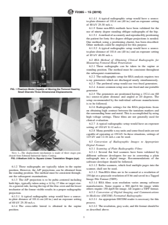
5.1 Aphysical phantom model which is capable of replicat-
posterior direction.
ing the three-dimensional displacement of the femoral head at
3.2.5 radio pair—one set of RSA radiographs which were
magnitudes of displacements that are expected to occur clini-
taken simultaneously.
cally should be used to validate new software programs,
modifications to existing programs, and variations to the
3.3 There are a number of computational methods that can
experimental protocol which may affect the results of the
beusedtomeasurecreep/wearofapolyethylenecomponent.A
measurements. A recent publication describes such a phantom
description of a few of the commonly used current methods is
and its use (6). Figs. 1 and 2 show an example of a model
given. This is not meant to be at the exclusion of other
which can be used for this purpose. For comparative purposes,
methods.
the method described by Bragdon et al (6) for calculating
3.3.1 Martell method—as this software is informally re-
accuracy and precision can be used. Illustrative values for the
ferred to in reference to its developer Dr. John Martell of
accuracyandprecisionasmeasuredbythismethodarelistedin
Chicago University, is a semi-automated computer technique
the appendix.
using edge detection and the Hough transformation for the
determination of polyethylene wear. This technique uses se-
5.2 To generate data for a precision and bias statement,
quential A/P films for two-dimensional analysis and A/P and
Practice E177 should be followed.
lateral sequential films for three dimensional analysis (2).
6. Material
3.3.2 Polywear method—a software program developed by
Dr. Peter Devane of the Wellington School of Medicine, New
6.1 Non-RSA Methods of Obtaining Clinical Radiographs
Zealand is a semi-automated computer technique using edge
for Measuring Femoral Head Penetration:
detection for the determination of polyethylene wear. This
6.1.1 These methods utilize anAnterior/Posterior (A/P) and
across-tablelateralprojectionofthepelvis.TheA/Pprojection
is used for measuring a two-dimensional penetration vector.
The cross-table lateral is used to determine the magnitude and
The boldface numbers in parentheses refer to the list of references at the end of
this standard. direction of the three-dimensional penetration vector.
F2385 − 15 (2019)
6.1.4.1 A typical radiographic setup would have a source-
to-plate distance of 101.6 cm (40 in.) and an exposure setting
of 80 kV 25-30 mA-s.
6.1.5 Some non-RSA methods have been validated for the
use of ninety degree standing oblique radiographs of the hip.
6.1.5.1 Amethodofaccuratelyandreproduciblypositioning
the patient for forty five degree oblique projections is needed.
One method, using a positioning chariot, has been described.
Other methods could be employed for this purpose.
6.1.5.2 A typical radiographic setup would have a source-
to-plate distance of 101.6 cm (40 in.) and an exposure setting
of 85 kV 40-50 mA-s.
6.2 RSA Method of Obtaining Clinical Radiographs for
Measuring Femoral Head Penetration:
6.2.1 These radiographs can be taken in the supine or
standing position. The method must be consistent throughout
the subsequent examinations.
6.2.2 The radiographic setup for RSAanalysis
...