


ASTM E2319-04(2019)
(Test Method)Standard Test Method for Determining Air Flow Through the Face and Sides of Exterior Windows, Curtain Walls, and Doors Under Specified Pressure Differences Across the Specimen
Standard Test Method for Determining Air Flow Through the Face and Sides of Exterior Windows, Curtain Walls, and Doors Under Specified Pressure Differences Across the Specimen
SIGNIFICANCE AND USE
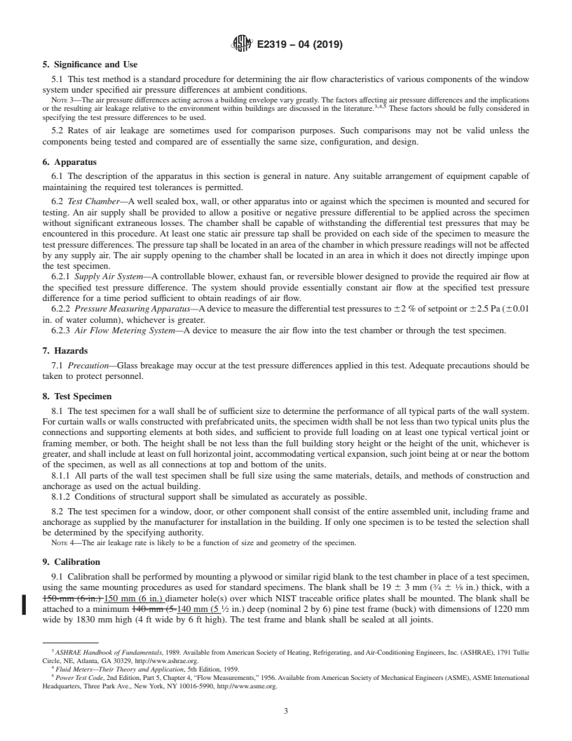
5.1 This test method is a standard procedure for determining the air flow characteristics of various components of the window system under specified air pressure differences at ambient conditions.
Note 3: The air pressure differences acting across a building envelope vary greatly. The factors affecting air pressure differences and the implications or the resulting air leakage relative to the environment within buildings are discussed in the literature.3 ,4,5 These factors should be fully considered in specifying the test pressure differences to be used.
5.2 Rates of air leakage are sometimes used for comparison purposes. Such comparisons may not be valid unless the components being tested and compared are of essentially the same size, configuration, and design.
SCOPE
1.1 This test method is a modified version of Test Method E283, and provides a standard laboratory procedure for determining air leakage separately through the face and sides of exterior windows, curtain walls, and doors under specified differential pressure conditions across the specimen. The test method described is for tests with constant temperature and humidity across the specimen.
Note 1: Detailing buildings with continuous air barriers requires that the air barrier plane in a window system be clearly defined. When special circumstances dictate that the air barrier be sealed to the window frame at a location other than that used to seal the specimen to the test chamber in this test method, additional laboratory testing may be required to clarify potential paths of air flow through the sides of the window frame. The adapted testing procedure described herein is intended for this purpose.
1.2 This laboratory procedure is applicable to exterior windows, curtain walls, and doors and is intended to measure only such leakage associated with the assembly and not the installation. The test method can be adapted for the latter purpose.
Note 2: Performing tests at non-ambient conditions or with a temperature differential across the specimen may affect the air leakage rate. This is not addressed by this test method.
1.3 This test method is intended for laboratory use. Persons interested in performing field air leakage tests on installed units should reference Test Method E783. Test Method E783 will not provide the user with a means of determining air flow through the sides of tested specimens.
1.4 Persons using this procedure should be knowledgeable in the areas of fluid mechanics, instrumentation practices, and shall have a general understanding of fenestration products and components.
1.5 The values stated in SI units are to be regarded as standard. The values given in parentheses are mathematical conversions to inch-pound units that are provided for information only and are not considered standard.
1.6 This standard does not purport to address all of the safety concerns, if any, associated with its use. It is the responsibility of the user of this standard to establish appropriate safety, health, and environmental practices and determine the applicability of regulatory limitations prior to use. For specific hazard statement see Section 7.
1.7 This international standard was developed in accordance with internationally recognized principles on standardization established in the Decision on Principles for the Development of International Standards, Guides and Recommendations issued by the World Trade Organization Technical Barriers to Trade (TBT) Committee.
General Information
Buy Standard


Standards Content (Sample)
NOTICE: This standard has either been superseded and replaced by a new version or withdrawn.
Contact ASTM International (www.astm.org) for the latest information
Designation:E2319 −04 (Reapproved 2019)
Standard Test Method for
Determining Air Flow Through the Face and Sides of
Exterior Windows, Curtain Walls, and Doors Under Specified
Pressure Differences Across the Specimen
This standard is issued under the fixed designation E2319; the number immediately following the designation indicates the year of
original adoption or, in the case of revision, the year of last revision.Anumber in parentheses indicates the year of last reapproval.A
superscript epsilon (´) indicates an editorial change since the last revision or reapproval.
1. Scope conversions to inch-pound units that are provided for informa-
tion only and are not considered standard.
1.1 This test method is a modified version of Test Method
E283, and provides a standard laboratory procedure for deter- 1.6 This standard does not purport to address all of the
safety concerns, if any, associated with its use. It is the
mining air leakage separately through the face and sides of
exterior windows, curtain walls, and doors under specified responsibility of the user of this standard to establish appro-
priate safety, health, and environmental practices and deter-
differential pressure conditions across the specimen. The test
method described is for tests with constant temperature and mine the applicability of regulatory limitations prior to use.
For specific hazard statement see Section 7.
humidity across the specimen.
NOTE 1—Detailing buildings with continuous air barriers requires that
1.7 This international standard was developed in accor-
the air barrier plane in a window system be clearly defined. When special
dance with internationally recognized principles on standard-
circumstances dictate that the air barrier be sealed to the window frame at
ization established in the Decision on Principles for the
a location other than that used to seal the specimen to the test chamber in
Development of International Standards, Guides and Recom-
this test method, additional laboratory testing may be required to clarify
mendations issued by the World Trade Organization Technical
potential paths of air flow through the sides of the window frame. The
adapted testing procedure described herein is intended for this purpose.
Barriers to Trade (TBT) Committee.
1.2 This laboratory procedure is applicable to exterior
2. Referenced Documents
windows, curtain walls, and doors and is intended to measure
only such leakage associated with the assembly and not the 2
2.1 ASTM Standards:
installation. The test method can be adapted for the latter
E283Test Method for Determining Rate of Air Leakage
purpose.
Through Exterior Windows, Curtain Walls, and Doors
NOTE 2—Performing tests at non-ambient conditions or with a tem-
Under Specified Pressure Differences Across the Speci-
perature differential across the specimen may affect the air leakage rate.
men
This is not addressed by this test method.
E631Terminology of Building Constructions
1.3 This test method is intended for laboratory use. Persons
E783Test Method for Field Measurement of Air Leakage
interestedinperformingfieldairleakagetestsoninstalledunits
Through Installed Exterior Windows and Doors
shouldreferenceTestMethodE783.TestMethodE783willnot
provide the user with a means of determining air flow through
3. Terminology
the sides of tested specimens.
3.1 Definitions—Terms used in this standard are defined in
1.4 Persons using this procedure should be knowledgeable
Terminology E631.
in the areas of fluid mechanics, instrumentation practices, and
3.2 Descriptions of Terms Specific to This Standard:
shallhaveageneralunderstandingoffenestrationproductsand
3.2.1 air leakage rate through the face of the specimen
components.
2 3 2 3
(q or q ), L/(s·m ) (ft /min·ft ), or L/(s·m) (ft /min·ft)
A(f) lc(f)
1.5 The values stated in SI units are to be regarded as
—the air leakage through the face of the specimen per unit of
standard. The values given in parentheses are mathematical
specimen area (A) or per unit length of operable crack
perimeter (lc).
This test method is under the jurisdiction of ASTM Committee E06 on
Performance of Buildings and is the direct responsibility of Subcommittee E06.51
on Performance of Windows, Doors, Skylights and Curtain Walls. For referenced ASTM standards, visit the ASTM website, www.astm.org, or
Current edition approved Jan. 1, 2019. Published January 2019. Originally contact ASTM Customer Service at service@astm.org. For Annual Book of ASTM
approved in 2004. Last previous edition approved in 2011 as E2319–04 (2011). Standards volume information, refer to the standard’s Document Summary page on
DOI: 10.1520/E2319–04R19. the ASTM website.
Copyright © ASTM International, 100 Barr Harbor Drive, PO Box C700, West Conshohocken, PA 19428-2959. United States
E2319−04 (2019)
3.2.2 air leakage rate through the face and sides of the 3.2.13 total air flow through face and sides (Q ), L/s
t(fs)
2 3 2 3
specimen (q ), L/(s·m ) (ft /min·ft )—the air leakage (ft /min)—the volume of air flowing per unit of time through
A(fs)
throughthefaceandsidesofthespecimenperunitofspecimen thetestchamberandtestapparatus,inclusiveoftheairflowing
area (A). through the face and sides of the test specimen, under a test
pressure difference and test temperature difference, converted
3.2.3 air leakage rate through the sides of the specimen
2 3 2 3 to standard conditions.
(q or q ), L/(s·m ) (ft /min·ft ), or L/(s·m) (ft /min·ft)
A(s) lf(s)
3.2.14 total air flow through sides (Q ), L/s (ft /min)—the
—the air leakage through the sides of the specimen per unit of t(s)
volumeofairflowingperunitoftimethroughthetestchamber
specimen area (A) or per unit length of outside perimeter of
and test apparatus, inclusive of the air flowing through the
specimen frame (lf).
sides of the test specimen but exclusive of the air flowing
3.2.4 air leakage through the face of the specimen (Q ),
s(f)
through the face of the specimen, under a test pressure
L/s (ft /min)—the volume of air flowing per unit of time
difference and test temperature difference, converted to stan-
through the face of the test specimen under a test pressure
dard conditions.
difference and test temperature difference, converted to stan-
3.2.15 unit length of operable crack perimeter (lc), m
dard conditions.
(ft)—the sum of all perimeters of operable ventilators, sash, or
3.2.5 air leakage through the face and sides of the specimen
doors contained in the test specimen, based on the overall
(Q ), L/s (ft /min)—the volume of air flowing per unit of
s(fs)
dimensions of such parts. Where two such operable parts meet
timethroughthefaceandsidesofthetestspecimenunderatest
the two adjacent lengths of perimeter shall be counted as only
pressure difference and test temperature difference, converted
one length.
to standard conditions.
3.2.16 unit length of outside perimeter of specimen frame
3.2.6 air leakage through the sides of the specimen (Q ),
s(s) (lf),m(ft)—theperimeterofthetestspecimen,measuredatthe
L/s (ft /min)—the volume of air flowing per unit of time
edge of the outer frame.
through the sides of the test specimen under a test pressure
difference and test temperature difference, converted to stan- 4. Summary of Test Method
dard conditions.
4.1 The test consists of sealing the interior and exterior of a
3.2.6.1 Discussion—Air leakage through the sides of the
test specimen into or against one face of an air chamber,
frame (Q ) is provided to inform specifiers of the potential
s(s) supplying air to or exhausting air from the chamber at the rate
leakage through the specimen at the window surrounds. The
required to maintain the specified test pressure difference
actual amount of leakage through the sides of the frame
across the specimen, and measuring the resultant air flow
depends on the positioning of the sealants, flashings and air
through the face and sides of the specimen.
barriers relative to the frame.
5. Significance and Use
3.2.7 extraneous air leakage (Q ), L/s (ft /min)—the vol-
e
5.1 Thistestmethodisastandardprocedurefordetermining
ume of air flowing per unit of time through the test chamber
the air flow characteristics of various components of the
and test apparatus, exclusive of the air flowing through the test
window system under specified air pressure differences at
specimen, under a test pressure difference and test temperature
ambient conditions.
difference, converted to standard conditions.
NOTE 3—The air pressure differences acting across a building envelope
3.2.7.1 Discussion—Extraneous leakage is the sum of all
vary greatly. The factors affecting air pressure differences and the
leakage other than that intended to be measured by the test.
implicationsortheresultingairleakagerelativetotheenvironmentwithin
3,4,5
buildings are discussed in the literature. These factors should be fully
3.2.8 specimen—theentireassembledunitsubmittedfortest
considered in specifying the test pressure differences to be used.
as described in Section 8.
5.2 Rates of air leakage are sometimes used for comparison
2 2
3.2.9 specimen area (A), m (ft )—the area determined by
purposes. Such comparisons may not be valid unless the
the overall dimensions of the frame that fits into the rough
components being tested and compared are of essentially the
opening.
same size, configuration, and design.
3.2.10 standard test conditions—in this test method, dry air
6. Apparatus
at:
Pressure—101.3 kPa (29.92 in. Hg) 6.1 The description of the apparatus in this section is
Temperature—20.8°C (69.4°F)
general in nature. Any suitable arrangement of equipment
3 3
Air Density—1.202 kg/m (0.075 lb/ft )
capableofmaintainingtherequiredtesttolerancesispermitted.
3.2.11 test pressure differences, Pa (lbf/ft ) —the specified
differential static air pressure across the specimen.
ASHRAE Handbook of Fundamentals, 1989.Available fromAmerican Society
3.2.12 total air flow through face (Q ), L/s (ft /min)—the
t(f)
of Heating, Refrigerating, and Air-Conditioning Engineers, Inc. (ASHRAE), 1791
volumeofairflowingperunitoftimethroughthetestchamber
Tullie Circle, NE, Atlanta, GA 30329, http://www.ashrae.org.
Fluid Meters—Their Theory and Application, 5th Edition, 1959.
andtestapparatus,inclusiveoftheairflowingthroughtheface
Power Test Code, 2nd Edition, Part 5, Chapter 4, “Flow Measurements,” 1956.
ofthetestspecimenbutexclusiveoftheairflowingthroughthe
Available from American Society of Mechanical Engineers (ASME), ASME
sides of the specimen, under a test pressure difference and test
International Headquarters, Three Park Ave., New York, NY 10016-5990, http://
temperature difference, converted to standard conditions. www.asme.org.
E2319−04 (2019)
6.2 Test Chamber—A well sealed box, wall, or other appa- specimen, using the same mounting procedures as used for
3 1
ratus into or against which the specimen is mounted and standard specimens. The blank shall be 19 63mm( ⁄4 6 ⁄8
secured for testing.An air supply shall be provided to allow a
in.) thick, with a 150 mm (6 in.) diameter hole(s) over which
positive or negative pressure differential to be applied across NISTtraceableorificeplatesshallbemounted.Theblankshall
the specimen without significant extraneous losses. The cham-
be attached to a minimum 140 mm (5 ⁄2 in.) deep (nominal 2
ber shall be capable of withstanding the differential test
by6)pinetestframe(buck)withdimensionsof1220mmwide
pressures that may be encountered in this procedure. At least
by 1830 mm high (4 ft wide by 6 ft high). The test frame and
one static air pressure tap shall be provided on each side of the
blank shall be sealed at all joints.
specimentomeasurethetestpressuredifferences.Thepressure
9.2 EachNISTtraceableorificeplateshallbeconstructedof
tapshallbelocatedinanareaofthechamberinwhichpressure
3mm( ⁄8 in.) thick stainless steel having an outside diameter
readings will not be affected by any supply air. The air supply
of 200 mm (8 in.) and interior square edge diameters of 25.40
opening to the chamber shall be located in an area in which it
mm (1.000 in.), 38.10 mm (1.500 in.) and 50.80 mm (2.000
does not directly impinge upon the test specimen.
in.).
6.2.1 Supply Air System—A controllable blower, exhaust
fan, or reversible blower designed to provide the required air
9.3 Fasten the orifice plate to the blank, centered over a 150
flowatthespecifiedtestpressuredifference.Thesystemshould
mm(6in.)diameterhole.Sealtheholeintheorificeplatewith
provide essentially constant air flow at the specified test
asuitableadhesivetapesothatanextraneousreadingontheair
pressure difference for a time period sufficient to obtain
flow system can be obtained. Measure the amount of such
readings of air flow.
leakage with the orifice plate sealed, at the air pressure
6.2.2 Pressure Measuring Apparatus—Adevice to measure
difference to be applied during calibration. After determining
the differential test pressures to 62% of setpoint or 62.5 Pa
the extraneous air leakage, remove the adhesive tape from the
(60.01 in. of water column), whichever is greater.
hole in the orifice plate and repeat the process to determine the
6.2.3 Air Flow Metering System—A device to measure the
total measured flow.
air flow into the test chamber or through the test specimen.
9.4 Calibration of the air leakage test equipment shall
7. Hazards
consist of determining the flow through the air flow system to
be calibrated using all applicable orifice plate sizes for the
7.1 Precaution—Glass breakage may occur at the test pres-
design range of the flow metering apparatus. The orifice plate
sure differences applied in this test. Adequate precautions
tobeusedforeachofthefollowingairflowrangesisindicated
should be taken to protect personnel.
in the table.
8. Test Specimen
NOTE 5—Three orifice plates are used to allow the air flow measuring
equipment to be used for a variety of specimen sizes and chamber/wall
8.1 Thetestspecimenforawallshallbeofsufficientsizeto
setups.
determine the performance of all typical parts of the wall
Orifice Plate Nominal Differential Pressure
system. For curtain walls or walls constructed with prefabri-
Hole Sizes Flow Across Orifice Plate
cated units, the specimen width shall be not less than two
25.4mm(1.0in.) 3.47L/s (7.36ft /min) 75 Pa (1.57 psf)
typical units plus the connections and supporting elements at
38.1 mm (1.5 in.) 7.66 L/s (16.24 ft /min) 75 Pa (1.57 psf)
50.8 mm (2.0 in.) 13.64 L/s (28.90 ft /min) 75 Pa (1.57 psf)
both sides, and sufficient to provide full loading on at least one
typical vertical joint or framing member, or both. The height
NOTE 6—At test pressures other than 75 Pa (1.57 psf), the laboratory
shallbenotlessthanthefullbuildingstoryheightortheheight
shallcalibratetheairflowmeasuringequipmentwiththeapplicableorifice
plates and record t
...
This document is not an ASTM standard and is intended only to provide the user of an ASTM standard an indication of what changes have been made to the previous version. Because
it may not be technically possible to adequately depict all changes accurately, ASTM recommends that users consult prior editions as appropriate. In all cases only the current version
of the standard as published by ASTM is to be considered the official document.
Designation: E2319 − 04 (Reapproved 2011) E2319 − 04 (Reapproved 2019)
Standard Test Method for
Determining Air Flow Through the Face and Sides of
Exterior Windows, Curtain Walls, and Doors Under Specified
Pressure Differences Across the Specimen
This standard is issued under the fixed designation E2319; the number immediately following the designation indicates the year of
original adoption or, in the case of revision, the year of last revision. A number in parentheses indicates the year of last reapproval. A
superscript epsilon (´) indicates an editorial change since the last revision or reapproval.
1. Scope
1.1 This test method is a modified version of Test Method E283, and provides a standard laboratory procedure for determining
air leakage separately through the face and sides of exterior windows, curtain walls, and doors under specified differential pressure
conditions across the specimen. The test method described is for tests with constant temperature and humidity across the specimen.
NOTE 1—Detailing buildings with continuous air barriers requires that the air barrier plane in a window system be clearly defined. When special
circumstances dictate that the air barrier be sealed to the window frame at a location other than that used to seal the specimen to the test chamber in this
test method, additional laboratory testing may be required to clarify potential paths of air flow through the sides of the window frame. The adapted testing
procedure described herein is intended for this purpose.
1.2 This laboratory procedure is applicable to exterior windows, curtain walls, and doors and is intended to measure only such
leakage associated with the assembly and not the installation. The test method can be adapted for the latter purpose.
NOTE 2—Performing tests at non-ambient conditions or with a temperature differential across the specimen may affect the air leakage rate. This is not
addressed by this test method.
1.3 This test method is intended for laboratory use. Persons interested in performing field air leakage tests on installed units
should reference Test Method E783. Test Method E783 will not provide the user with a means of determining air flow through the
sides of tested specimens.
1.4 Persons using this procedure should be knowledgeable in the areas of fluid mechanics, instrumentation practices, and shall
have a general understanding of fenestration products and components.
1.5 The values stated in SI units are to be regarded as standard. The values given in parentheses are mathematical conversions
to inch-pound units that are provided for information only and are not considered standard.
1.6 This standard does not purport to address all of the safety concerns, if any, associated with its use. It is the responsibility
of the user of this standard to establish appropriate safety safety, health, and healthenvironmental practices and determine the
applicability of regulatory limitations prior to use. For specific hazard statement see Section 7.
1.7 This international standard was developed in accordance with internationally recognized principles on standardization
established in the Decision on Principles for the Development of International Standards, Guides and Recommendations issued
by the World Trade Organization Technical Barriers to Trade (TBT) Committee.
2. Referenced Documents
2.1 ASTM Standards:
E283 Test Method for Determining Rate of Air Leakage Through Exterior Windows, Curtain Walls, and Doors Under Specified
Pressure Differences Across the Specimen
E631 Terminology of Building Constructions
E783 Test Method for Field Measurement of Air Leakage Through Installed Exterior Windows and Doors
3. Terminology
3.1 Definitions—Terms used in this standard are defined in Terminology E631.
3.2 Descriptions of Terms Specific to This Standard:
This test method is under the jurisdiction of ASTM Committee E06 on Performance of Buildings and is the direct responsibility of Subcommittee E06.51 on Performance
of Windows, Doors, Skylights and Curtain Walls.
Current edition approved Nov. 1, 2011Jan. 1, 2019. Published December 2011January 2019. Originally approved in 2004. Last previous edition approved in 20042011
as E2319 – 04.E2319–04 (2011). DOI: 10.1520/E2319-04R11.10.1520/E2319–04R19.
For referenced ASTM standards, visit the ASTM website, www.astm.org, or contact ASTM Customer Service at service@astm.org. For Annual Book of ASTM Standards
volume information, refer to the standard’sstandard’s Document Summary page on the ASTM website.
Copyright © ASTM International, 100 Barr Harbor Drive, PO Box C700, West Conshohocken, PA 19428-2959. United States
E2319 − 04 (2019)
2 3 2 3
3.2.1 air leakage rate through the face of the specimen (q or q ), L/(s·m ) (ft /min·ft ), or L/(s·m) (ft /min·ft) —the air
A(f) lc(f)
leakage through the face of the specimen per unit of specimen area (A) or per unit length of operable crack perimeter (lc).
2 3 2
3.2.2 air leakage rate through the face and sides of the specimen (q ), L/(s·m ) (ft /min·ft )—the air leakage through the face
A(fs)
and sides of the specimen per unit of specimen area (A).
2 3 2 3
3.2.3 air leakage rate through the sides of the specimen (q or q ), L/(s·m ) (ft /min·ft ), or L/(s·m) (ft /min·ft) —the air
A(s) lf(s)
leakage through the sides of the specimen per unit of specimen area (A) or per unit length of outside perimeter of specimen frame
(lf).
3.2.4 air leakage through the face of the specimen (Q ), L/s (ft /min)—the volume of air flowing per unit of time through the
s(f)
face of the test specimen under a test pressure difference and test temperature difference, converted to standard conditions.
3.2.5 air leakage through the face and sides of the specimen (Q ), L/s (ft /min)—the volume of air flowing per unit of time
s(fs)
through the face and sides of the test specimen under a test pressure difference and test temperature difference, converted to
standard conditions.
3.2.6 air leakage through the sides of the specimen (Q ), L/s (ft /min)—the volume of air flowing per unit of time through
s(s)
the sides of the test specimen under a test pressure difference and test temperature difference, converted to standard conditions.
3.2.6.1 Discussion—
Air leakage through the sides of the frame (Q ) is provided to inform specifiers of the potential leakage through the specimen
s(s)
at the window surrounds. The actual amount of leakage through the sides of the frame depends on the positioning of the sealants,
flashings and air barriers relative to the frame.
3.2.7 extraneous air leakage (Q ), L/s (ft /min)—the volume of air flowing per unit of time through the test chamber and test
e
apparatus, exclusive of the air flowing through the test specimen, under a test pressure difference and test temperature difference,
converted to standard conditions.
3.2.7.1 Discussion—
Extraneous leakage is the sum of all leakage other than that intended to be measured by the test.
3.2.8 specimen—the entire assembled unit submitted for test as described in Section 8.
2 2
3.2.9 specimen area (A), m (ft )—the area determined by the overall dimensions of the frame that fits into the rough opening.
3.2.10 standard test conditions—in this test method, dry air at:
Pressure—101.3 kPa (29.92 in. Hg)
Temperature—20.8°C (69.4°F)
3 3
Air Density—1.202 kg/m (0.075 lb/ft )
3.2.11 test pressure differences, Pa (lbf/ft ) —the specified differential static air pressure across the specimen.
3.2.12 total air flow through face (Q ), L/s (ft /min)—the volume of air flowing per unit of time through the test chamber and
t(f)
test apparatus, inclusive of the air flowing through the face of the test specimen but exclusive of the air flowing through the sides
of the specimen, under a test pressure difference and test temperature difference, converted to standard conditions.
3.2.13 total air flow through face and sides (Q ), L/s (ft /min)—the volume of air flowing per unit of time through the test
t(fs)
chamber and test apparatus, inclusive of the air flowing through the face and sides of the test specimen, under a test pressure
difference and test temperature difference, converted to standard conditions.
3.2.14 total air flow through sides (Q ), L/s (ft /min)—the volume of air flowing per unit of time through the test chamber and
t(s)
test apparatus, inclusive of the air flowing through the sides of the test specimen but exclusive of the air flowing through the face
of the specimen, under a test pressure difference and test temperature difference, converted to standard conditions.
3.2.15 unit length of operable crack perimeter (lc), m (ft)—the sum of all perimeters of operable ventilators, sash, or doors
contained in the test specimen, based on the overall dimensions of such parts. Where two such operable parts meet the two adjacent
lengths of perimeter shall be counted as only one length.
3.2.16 unit length of outside perimeter of specimen frame (lf), m (ft)—the perimeter of the test specimen, measured at the edge
of the outer frame.
4. Summary of Test Method
4.1 The test consists of sealing the interior and exterior of a test specimen into or against one face of an air chamber, supplying
air to or exhausting air from the chamber at the rate required to maintain the specified test pressure difference across the specimen,
and measuring the resultant air flow through the face and sides of the specimen.
E2319 − 04 (2019)
5. Significance and Use
5.1 This test method is a standard procedure for determining the air flow characteristics of various components of the window
system under specified air pressure differences at ambient conditions.
NOTE 3—The air pressure differences acting across a building envelope vary greatly. The factors affecting air pressure differences and the implications
3,4,5
or the resulting air leakage relative to the environment within buildings are discussed in the literature. These factors should be fully considered in
specifying the test pressure differences to be used.
5.2 Rates of air leakage are sometimes used for comparison purposes. Such comparisons may not be valid unless the
components being tested and compared are of essentially the same size, configuration, and design.
6. Apparatus
6.1 The description of the apparatus in this section is general in nature. Any suitable arrangement of equipment capable of
maintaining the required test tolerances is permitted.
6.2 Test Chamber—A well sealed box, wall, or other apparatus into or against which the specimen is mounted and secured for
testing. An air supply shall be provided to allow a positive or negative pressure differential to be applied across the specimen
without significant extraneous losses. The chamber shall be capable of withstanding the differential test pressures that may be
encountered in this procedure. At least one static air pressure tap shall be provided on each side of the specimen to measure the
test pressure differences. The pressure tap shall be located in an area of the chamber in which pressure readings will not be affected
by any supply air. The air supply opening to the chamber shall be located in an area in which it does not directly impinge upon
the test specimen.
6.2.1 Supply Air System—A controllable blower, exhaust fan, or reversible blower designed to provide the required air flow at
the specified test pressure difference. The system should provide essentially constant air flow at the specified test pressure
difference for a time period sufficient to obtain readings of air flow.
6.2.2 Pressure Measuring Apparatus—A device to measure the differential test pressures to 62 % of setpoint or 62.5 Pa (60.01
in. of water column), whichever is greater.
6.2.3 Air Flow Metering System—A device to measure the air flow into the test chamber or through the test specimen.
7. Hazards
7.1 Precaution—Glass breakage may occur at the test pressure differences applied in this test. Adequate precautions should be
taken to protect personnel.
8. Test Specimen
8.1 The test specimen for a wall shall be of sufficient size to determine the performance of all typical parts of the wall system.
For curtain walls or walls constructed with prefabricated units, the specimen width shall be not less than two typical units plus the
connections and supporting elements at both sides, and sufficient to provide full loading on at least one typical vertical joint or
framing member, or both. The height shall be not less than the full building story height or the height of the unit, whichever is
greater, and shall include at least on full horizontal joint, accommodating vertical expansion, such joint being at or near the bottom
of the specimen, as well as all connections at top and bottom of the units.
8.1.1 All parts of the wall test specimen shall be full size using the same materials, details, and methods of construction and
anchorage as used on the actual building.
8.1.2 Conditions of structural support shall be simulated as accurately as possible.
8.2 The test specimen for a window, door, or other component shall consist of the entire assembled unit, including frame and
anchorage as supplied by the manufacturer for installation in the building. If only one specimen is to be tested the selection shall
be determined by the specifying authority.
NOTE 4—The air leakage rate is likely to be a function of size and geometry of the specimen.
9. Calibration
9.1 Calibration shall be performed by mounting a plywood or similar rigid blank to the test chamber in place of a test specimen,
3 1
using the same mounting procedures as used for standard specimens. The blank shall be 19 6 3 mm ( ⁄4 6 ⁄8 in.) thick, with a
150-mm (6-in.) 150 mm (6 in.) diameter hole(s) over which NIST traceable orifice plates shall be mounted. The blank shall be
attached to a minimum 140-mm (5-140 mm (5 ⁄2 in.) deep (nominal 2 by 6) pine test frame (buck) with dimensions of 1220 mm
wide by 1830 mm high (4 ft wide by 6 ft high). The test frame and blank shall be sealed at all joints.
ASHRAE Handbook of Fundamentals, 1989. Available from American Society of Heating, Refrigerating, and Air-Conditioning Engineers, Inc. (ASHRAE), 1791 Tullie
Circle, NE, Atlanta, GA 30329, http://www.ashrae.org.
Fluid Meters—Their Theory and Application, 5th Edition, 1959.
Power Test Code, 2nd Edition, Part 5, Chapter 4, “Flow Measurements,” 1956. Available from American Society of Mechanical Engineers (ASME), ASME International
Headquarters, Three Park Ave., New Yor
...
Questions, Comments and Discussion
Ask us and Technical Secretary will try to provide an answer. You can facilitate discussion about the standard in here.