

ASTM F2723-21
(Test Method)Standard Test Method for Evaluating Mobile Bearing Knee Tibial Baseplate/Bearing Resistance to Dynamic Disassociation
General Information
- Abstract
SIGNIFICANCE AND USE
3.1 This test method includes the use of static and fatigue shear and bending force conditions to evaluate the bearing retention mechanism of a mobile bearing knee design and its ability to prevent disassociation.
3.2 In general, disassociation does not occur during activities where the contact locations are within the boundaries of the bearing surfaces. Disassociation is most likely to occur with forces at the edges of the bearing component or with large AP shear forces on a posterior stabilized knee tibial component post. Extreme bearing rotation, bone/bearing impingement, severe varus or valgus moments, high flexion, or any combination of these can increase the likelihood of disassociation.
3.3 The test method described is applicable to any bicompartmental mobile bearing knee with a bearing retention mechanism. With modification, the test can be applied to a unicompartmental mobile bearing knee with a bearing retention mechanism.
SCOPE
1.1 This test method describes a laboratory method for evaluating the potential for mobile bearing knee tibial baseplate/bearing disassociation under repeated forces.
1.2 The test described is applicable to any bicompartmental mobile bearing knee with a bearing retention mechanism. With modification, the test can be applied to a unicompartmental mobile bearing knee with a bearing retention mechanism.
1.3 Although the methodology described does not replicate all physiological force conditions, it is a means of in-vitro comparison of mobile bearing knee designs and the strength of the bearing retention mechanism between the tibial baseplate and bearing components under the stated test conditions.
1.4 The values stated in SI units are to be regarded as standard. No other units of measurement are included in this standard.
1.5 This standard does not purport to address all of the safety concerns, if any, associated with its use. It is the responsibility of the user of this standard to establish appropriate safety, health, and environmental practices and determine the applicability of regulatory limitations prior to use.
1.6 This international standard was developed in accordance with internationally recognized principles on standardization established in the Decision on Principles for the Development of International Standards, Guides and Recommendations issued by the World Trade Organization Technical Barriers to Trade (TBT) Committee.
- Status
- Published
- Publication Date
- 28-Feb-2021
- Technical Committee
- F04 - Medical and Surgical Materials and Devices
- Drafting Committee
- F04.22 - Arthroplasty
Buy Documents
ASTM F2723-21 - Standard Test Method for Evaluating Mobile Bearing Knee Tibial Baseplate/Bearing Resistance to Dynamic Disassociation
REDLINE ASTM F2723-21 - Standard Test Method for Evaluating Mobile Bearing Knee Tibial Baseplate/Bearing Resistance to Dynamic Disassociation
Overview
ASTM F2723-21 sets forth standardized test procedures for evaluating the resistance of mobile bearing knee tibial baseplate/bearing assemblies to dynamic disassociation. Developed by ASTM International, this test method is especially significant for manufacturers and research institutions involved in the development and assessment of mobile bearing knee prostheses. The goal of this standard is to simulate laboratory conditions that apply repetitive forces to the prosthetic components, thereby assessing the strength and reliability of the bearing retention mechanism under cyclic shear and bending loads.
ASTM F2723-21 applies to both bicompartmental and unicompartmental mobile bearing knee designs featuring a bearing retention mechanism. While it does not replicate every physiological scenario, it delivers a reproducible means for in-vitro comparison across various knee implant designs within standardized parameters.
Key Topics
- Purpose of Testing: To quantify the capacity of mobile bearing knee systems, specifically the tibial baseplate and bearing assembly, to withstand dynamic loading and prevent disassociation.
- Test Conditions: Involves both static and dynamic (fatigue) loading scenarios, including shear forces, bending moments, and repetitive cycling. Testing focuses primarily on forces acting at the edges or during high flexion situations, considered most likely to cause disassociation.
- Component Compatibility: The standard encompasses any bicompartmental mobile bearing knee, and with modifications, is applicable to unicompartmental designs.
- Measurement Requirements:
- Use of a two-axis orthogonal load frame for force/displacement control and measurement
- Preconditioning of specimens
- Monitoring of vertical distraction, posterior bearing tilt, and cumulative displacement after cyclic loading
- Reporting: Detailed requirements for documenting test conditions, material traceability, apparatus setup, and observed outcomes, including any instances of bearing disassociation or mechanical failure.
Applications
- Device Development and Validation: Orthopedic device manufacturers employ ASTM F2723-21 to validate the durability and stability of mobile bearing knee prostheses before clinical application. The results help refine design features such as bearing retention mechanisms to improve implant longevity and patient safety.
- Comparative Assessment: Enables in-vitro comparison of different mobile bearing knee prosthesis models within controlled conditions, providing valuable data for competitive benchmarking or regulatory submission.
- Risk Mitigation: By stress-testing implants at force extremes, developers can identify potential failure modes under daily living and high-stress scenarios, supporting compliance with safety, health, and environmental regulations.
- Regulatory and Quality Assurance: Satisfies an essential requirement for demonstrating product reliability to regulatory bodies and supporting technical documentation for CE marking, FDA clearance, or equivalent market approval processes.
Related Standards
- ASTM F1223 - Standard Test Method for Determination of Total Knee Replacement Constraint, providing additional test methodology for assessing constraint forces in total knee replacement devices.
- ISO 14243 - Implants for surgery - Wear testing of total knee-joint prostheses, focusing on wear characteristics under cyclic loadings.
- ASTM F2083 - Standard Specification for Total Knee Replacement Prostheses, which sets out general requirements for knee replacement devices.
- ISO 7207-2 - Implants for surgery - Components for partial and total knee joint prostheses.
By adhering to ASTM F2723-21, stakeholders in the orthopedic medical device sector enhance product reliability, ensure compliance with international best practices, and contribute to greater patient safety and clinical success in knee arthroplasty. For full technical details and updates, always refer to the official ASTM standard document.
Buy Documents
ASTM F2723-21 - Standard Test Method for Evaluating Mobile Bearing Knee Tibial Baseplate/Bearing Resistance to Dynamic Disassociation
REDLINE ASTM F2723-21 - Standard Test Method for Evaluating Mobile Bearing Knee Tibial Baseplate/Bearing Resistance to Dynamic Disassociation
Get Certified
Connect with accredited certification bodies for this standard

BSI Group
BSI (British Standards Institution) is the business standards company that helps organizations make excellence a habit.

TÜV Rheinland
TÜV Rheinland is a leading international provider of technical services.

TÜV SÜD
TÜV SÜD is a trusted partner of choice for safety, security and sustainability solutions.
Sponsored listings
Frequently Asked Questions
ASTM F2723-21 is a standard published by ASTM International. Its full title is "Standard Test Method for Evaluating Mobile Bearing Knee Tibial Baseplate/Bearing Resistance to Dynamic Disassociation". This standard covers: SIGNIFICANCE AND USE 3.1 This test method includes the use of static and fatigue shear and bending force conditions to evaluate the bearing retention mechanism of a mobile bearing knee design and its ability to prevent disassociation. 3.2 In general, disassociation does not occur during activities where the contact locations are within the boundaries of the bearing surfaces. Disassociation is most likely to occur with forces at the edges of the bearing component or with large AP shear forces on a posterior stabilized knee tibial component post. Extreme bearing rotation, bone/bearing impingement, severe varus or valgus moments, high flexion, or any combination of these can increase the likelihood of disassociation. 3.3 The test method described is applicable to any bicompartmental mobile bearing knee with a bearing retention mechanism. With modification, the test can be applied to a unicompartmental mobile bearing knee with a bearing retention mechanism. SCOPE 1.1 This test method describes a laboratory method for evaluating the potential for mobile bearing knee tibial baseplate/bearing disassociation under repeated forces. 1.2 The test described is applicable to any bicompartmental mobile bearing knee with a bearing retention mechanism. With modification, the test can be applied to a unicompartmental mobile bearing knee with a bearing retention mechanism. 1.3 Although the methodology described does not replicate all physiological force conditions, it is a means of in-vitro comparison of mobile bearing knee designs and the strength of the bearing retention mechanism between the tibial baseplate and bearing components under the stated test conditions. 1.4 The values stated in SI units are to be regarded as standard. No other units of measurement are included in this standard. 1.5 This standard does not purport to address all of the safety concerns, if any, associated with its use. It is the responsibility of the user of this standard to establish appropriate safety, health, and environmental practices and determine the applicability of regulatory limitations prior to use. 1.6 This international standard was developed in accordance with internationally recognized principles on standardization established in the Decision on Principles for the Development of International Standards, Guides and Recommendations issued by the World Trade Organization Technical Barriers to Trade (TBT) Committee.
SIGNIFICANCE AND USE 3.1 This test method includes the use of static and fatigue shear and bending force conditions to evaluate the bearing retention mechanism of a mobile bearing knee design and its ability to prevent disassociation. 3.2 In general, disassociation does not occur during activities where the contact locations are within the boundaries of the bearing surfaces. Disassociation is most likely to occur with forces at the edges of the bearing component or with large AP shear forces on a posterior stabilized knee tibial component post. Extreme bearing rotation, bone/bearing impingement, severe varus or valgus moments, high flexion, or any combination of these can increase the likelihood of disassociation. 3.3 The test method described is applicable to any bicompartmental mobile bearing knee with a bearing retention mechanism. With modification, the test can be applied to a unicompartmental mobile bearing knee with a bearing retention mechanism. SCOPE 1.1 This test method describes a laboratory method for evaluating the potential for mobile bearing knee tibial baseplate/bearing disassociation under repeated forces. 1.2 The test described is applicable to any bicompartmental mobile bearing knee with a bearing retention mechanism. With modification, the test can be applied to a unicompartmental mobile bearing knee with a bearing retention mechanism. 1.3 Although the methodology described does not replicate all physiological force conditions, it is a means of in-vitro comparison of mobile bearing knee designs and the strength of the bearing retention mechanism between the tibial baseplate and bearing components under the stated test conditions. 1.4 The values stated in SI units are to be regarded as standard. No other units of measurement are included in this standard. 1.5 This standard does not purport to address all of the safety concerns, if any, associated with its use. It is the responsibility of the user of this standard to establish appropriate safety, health, and environmental practices and determine the applicability of regulatory limitations prior to use. 1.6 This international standard was developed in accordance with internationally recognized principles on standardization established in the Decision on Principles for the Development of International Standards, Guides and Recommendations issued by the World Trade Organization Technical Barriers to Trade (TBT) Committee.
ASTM F2723-21 is classified under the following ICS (International Classification for Standards) categories: 11.040.40 - Implants for surgery, prosthetics and orthotics. The ICS classification helps identify the subject area and facilitates finding related standards.
ASTM F2723-21 is available in PDF format for immediate download after purchase. The document can be added to your cart and obtained through the secure checkout process. Digital delivery ensures instant access to the complete standard document.
Standards Content (Sample)
This international standard was developed in accordance with internationally recognized principles on standardization established in the Decision on Principles for the
Development of International Standards, Guides and Recommendations issued by the World Trade Organization Technical Barriers to Trade (TBT) Committee.
Designation: F2723 − 21
Standard Test Method for
Evaluating Mobile Bearing Knee Tibial Baseplate/Bearing
Resistance to Dynamic Disassociation
This standard is issued under the fixed designation F2723; the number immediately following the designation indicates the year of
original adoption or, in the case of revision, the year of last revision. A number in parentheses indicates the year of last reapproval. A
superscript epsilon (´) indicates an editorial change since the last revision or reapproval.
1. Scope 2.1.3 inferior articulating interfaces—any interface in
which relative motion occurs between the underside of the
1.1 This test method describes a laboratory method for
mobile bearing component and the tibial tray.
evaluating the potential for mobile bearing knee tibial
baseplate/bearing disassociation under repeated forces. 2.1.4 limiting position—the position of the femoral compo-
nent relative to the bearing at which the shear force is at a
1.2 The test described is applicable to any bicompartmental
maximum with anterior-posterior (AP) movement of the femo-
mobile bearing knee with a bearing retention mechanism. With
ral component on the bearing.
modification, the test can be applied to a unicompartmental
2.1.5 mobile bearing—the component between fixed femo-
mobile bearing knee with a bearing retention mechanism.
ral and tibial knee components with an articulating surface on
1.3 Although the methodology described does not replicate
both the inferior and superior sides.
all physiological force conditions, it is a means of in-vitro
2.1.6 mobile bearing knee system—a knee prosthesis
comparison of mobile bearing knee designs and the strength of
system, comprising a tibial component, a mobile bearing
the bearing retention mechanism between the tibial baseplate
component that can rotate or rotate and translate relative to the
and bearing components under the stated test conditions.
tibial component, and a femoral component.
1.4 The values stated in SI units are to be regarded as
2.1.7 superior articulating interfaces—any interface in
standard. No other units of measurement are included in this
whichrelativemotionoccursbetweenthetopsideofthemobile
standard.
bearing component and the femoral bearing component.
1.5 This standard does not purport to address all of the
2.1.8 tibial baseplate/bearing disassociation—
safety concerns, if any, associated with its use. It is the
unrecoverable physical separation of the bearing and tibial
responsibility of the user of this standard to establish appro-
baseplate components as a result of bearing distraction or
priate safety, health, and environmental practices and deter-
tilting.
mine the applicability of regulatory limitations prior to use.
1.6 This international standard was developed in accor-
2.1.9 two-axis orthogonal load frame—a test machine ca-
dance with internationally recognized principles on standard-
pable of applying forces and displacements that act at 90° to
ization established in the Decision on Principles for the
each other.
Development of International Standards, Guides and Recom-
mendations issued by the World Trade Organization Technical
3. Significance and Use
Barriers to Trade (TBT) Committee.
3.1 This test method includes the use of static and fatigue
shear and bending force conditions to evaluate the bearing
2. Terminology
retention mechanism of a mobile bearing knee design and its
2.1 Definitions:
ability to prevent disassociation.
2.1.1 bearing axis—the line connecting the lowest points on
3.2 In general, disassociation does not occur during activi-
both the lateral and medial condyles of the superior surface of
tieswherethecontactlocationsarewithintheboundariesofthe
the mobile bearing.
bearing surfaces. Disassociation is most likely to occur with
2.1.2 bearing retention mechanism—mechanical means pre-
forces at the edges of the bearing component or with large AP
venting tibial baseplate/bearing disassociation.
shear forces on a posterior stabilized knee tibial component
post. Extreme bearing rotation, bone/bearing impingement,
This test method is under the jurisdiction ofASTM Committee F04 on Medical
severe varus or valgus moments, high flexion, or any combi-
and Surgical Materials and Devices and is the direct responsibility of Subcommittee
F04.22 on Arthroplasty. nation of these can increase the likelihood of disassociation.
Current edition approved March 1, 2021. Published March 2021. Originally
3.3 The test method described is applicable to any bicom-
approved in 2008. Last previous version approved in 2013 as F2723 – 13a. DOI:
10.1520/F2723-21. partmental mobile bearing knee with a bearing retention
Copyright © ASTM International, 100 Barr Harbor Drive, PO Box C700, West Conshohocken, PA 19428-2959. United States
F2723 − 21
mechanism. With modification, the test can be applied to a
unicompartmental mobile bearing knee with a bearing reten-
tion mechanism.
4. Apparatus and Materials
4.1 Atwo-axis orthogonal load frame with feedback control
on both axes is required for dislocation testing. The machine
must be able to record force and displacement in both axes.
4.1.1 Component Size—Test specimens should be chosen to
maximize the force on the bearing retention mechanism.
Considerations should include bearing thickness (a thicker
bearing would tend to increase the forces on the locking
mechanism, but could also increase the material support for the
locking mechanism), bearing profile/size, and tibial baseplate
profile/size (a large bearing on a small tibial baseplate would
tend to increase the overhang with rotation).
4.1.2 Component Quantity—The minimum number of test
samples shall be five.
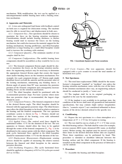
4.2 Component Configurations—The mobile bearing knee
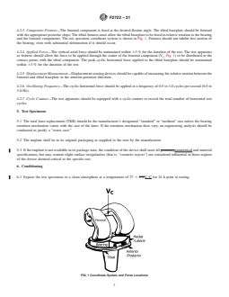
FIG. 1 Coordinate System and Force Locations
components should be assembled, as they would be for in-vivo
use.
4.2.1 The femoral component flexion angle should be cho-
sen to maximize the forces on the bearing retention mecha-
4.2.7 Cycle Counter—The test apparatus should be
nism. An engineering analysis may be necessary to determine
equipped with a cycle counter to record the total number of
the appropriate femoral flexion angle that creates the largest
horizontal test cycles.
shear and/or bending forces on the retention mechanisms. For
example, for a gait congruent design, a 0° flexion angle might
5. Test Specimens
distribute forces on both the anterior and the posterior sides of
5.1 The total knee replacement (TKR) should be the manu-
the locking mechanism, minimizing any bending forces. A
facturer’s designated “standard” or “medium” size unless the
flexion angle of greater than 90° may maximize the posterior
bearing retention mechanism varies with the size of the knee.
position of the femoral component and consequently increase
If the retention mechanism does vary, an engineering analysis
bending forces on the retention mechanism.
should be conducted to justify a “worst case.”
4.2.2 The tibial baseplate should be positioned with the
5.2 The implant shall be in its original packaging as
recommended posterior slope. For knee systems where more
supplied to the user by the manufacturer.
than one posterior slope is recommended, the largest slope
should be used.
5.3 If the implant is not available in its package state, the
4.2.3 Component Fixtures—The femoral component is fixed
condition of the device shall meet all geometrical and material
at the desired flexion angle. The tibial baseplate should be
specifications, but may contain slight surface irregularities
fixtured with the appropriate posterior slope. The tibial fixtures
(that is, “cosmetic rejects”) not considered influential in those
must allow the tibial baseplate to be fixed in relative rotation to
regions of the device deemed critical to the specific test.
the bearing and the femoral components. The test specimen
coordinate system is shown in Fig. 1. Fixtures should not
6. Conditioning
inhibit free motion of the bearing, even with substantial
6.1 Expose the test specimens to a clean atmosphere at a
deformation if it should occur.
temperature of 37 6 2 °C for 24 h prior to testing.
4.2.4 Applied Force—The vertical axial force should be
6.2 The test shall be run in a bath at 37 6 2 °C that covers
maintained within 63 % for the duration of the test. The test
the tibial bearing surface.The bath shall be water (for example,
apparatus or fixtures should allow the force to be applied
reverse osmosis (RO) water, deionized (DI) water, or distilled
through the center of the femoral component (V , Fig. 1)tobe
c
water). Before testing, the implant must be moved cyclically
distributed to the contact points with the tibial component. The
three times in the desired direction before data are acquired.
peak cyclic horizontal force applied to the tibial baseplate
These three repetitions can be performed by hand. This
should be maintained within 63 % for the duration of the test.
procedure is intended to distribute lubricant between the
4.2.5 Displacement Measurement—Displacement sensing
bearing surface and the tibial component. If the bearing is
devices should be capable of measuring the relative motion
installed on the tibial component in the presence of lubricant it
between the femoral and tibial baseplate in the anterior-
can be omitted.
posterior direction.
4.2.6 Oscillating Frequency—The cyclic horizontal force
7. Procedure
should be applied at a frequency of 0.5 to 3.0 cycles per second
(0.5 to 3.0 Hz). 7.1 Assemble the bearing and tibial baseplate.
F2723 − 21
7.2 Measure vertical distraction (when appropriate for the additional preconditioning of the tibial component is required.
design)andposteriorbearingtiltdisplacement(Fig.2).Change In that case, perform the procedure of 7.5.1 multiple times,
in these displacements after testing may be useful as an recording the force each time, until the force difference
indicator of damage. between successive runs falls below 5 %. Use 90 % of the
7.2.1 To measure the vertical distraction, use plastic blade- force measured in the last run made as the posterior-to-anterior
type feeler gauges of an appropriate range to measure the limit force for the cycle test of 7.7.
amountofdistraction.Thegaugebladesshouldbelongenough
7.5.2 Apply an anterior-to-posterior horizontal force to the
to completely fit under the full length of the bearing. One set
tibial base plate until the horizontal force reaches 450 N or the
shall be placed under each condyle to lift the bearing away
femoral reaches a point where the horizontal force drops
from the tibial plate keeping the posterior surface of the
because the femur has crossed over the anterior edge of the
bearing parallel to the superior surface of the tibial plate, until
tibial component. The plot ofAPforce versusAPdisplacement
the gauges will not fit in the gap without force. The thickness
is continuously recorded.
of the feeler gauges is the vertical distraction value.
7.5.2.1 If the force reaches 450 N, the anterior-to-posterior
7.2.2 To measure the posterior bearing tilt displacement,
limit force is 450 N.
push the bearing posteriorly and raise the posterior edge of the
7.5.2.2 If the force drops off before 450
...
This document is not an ASTM standard and is intended only to provide the user of an ASTM standard an indication of what changes have been made to the previous version. Because
it may not be technically possible to adequately depict all changes accurately, ASTM recommends that users consult prior editions as appropriate. In all cases only the current version
of the standard as published by ASTM is to be considered the official document.
Designation: F2723 − 13a F2723 − 21
Standard Test Method for
Evaluating Mobile Bearing Knee Tibial Baseplate/Bearing
Resistance to Dynamic Disassociation
This standard is issued under the fixed designation F2723; the number immediately following the designation indicates the year of
original adoption or, in the case of revision, the year of last revision. A number in parentheses indicates the year of last reapproval. A
superscript epsilon (´) indicates an editorial change since the last revision or reapproval.
1. Scope
1.1 This test method describes a laboratory method for evaluating the potential for mobile bearing knee tibial baseplate/bearing
disassociation under repeated forces.
1.2 The test described is applicable to any bicompartmental mobile bearing knee with a bearing retention mechanism. With
modification, the test can be applied to a unicompartmental mobile bearing knee with a bearing retention mechanism.
1.3 Although the methodology described does not replicate all physiological force conditions, it is a means of in vitroin-vitro
comparison of mobile bearing knee designs and the strength of the bearing retention mechanism between the tibial baseplate and
bearing components under the stated test conditions.
1.4 The values stated in SI units are to be regarded as standard. No other units of measurement are included in this standard.
1.5 This standard does not purport to address all of the safety concerns, if any, associated with its use. It is the responsibility
of the user of this standard to establish appropriate safety safety, health, and healthenvironmental practices and determine the
applicability of regulatory limitations prior to use.
1.6 This international standard was developed in accordance with internationally recognized principles on standardization
established in the Decision on Principles for the Development of International Standards, Guides and Recommendations issued
by the World Trade Organization Technical Barriers to Trade (TBT) Committee.
2. Terminology
2.1 Definitions:
2.1.1 bearing axis—the line connecting the lowest points on both the lateral and medial condyles of the superior surface of the
mobile bearing.
2.1.2 bearing retention mechanism—mechanical means preventing tibial baseplate/bearing disassociation.
2.1.3 inferior articulating interfaces—any interface in which relative motion occurs between the underside of the mobile bearing
component and the tibial tray.
This test method is under the jurisdiction of ASTM Committee F04 on Medical and Surgical Materials and Devices and is the direct responsibility of Subcommittee
F04.22 on Arthroplasty.
Current edition approved July 15, 2013March 1, 2021. Published August 2013March 2021. Originally approved in 2008. Last previous version approved in 2013 as
F2723 – 13.F2723 – 13a. DOI: 10.1520/F2723-13A.10.1520/F2723-21.
Copyright © ASTM International, 100 Barr Harbor Drive, PO Box C700, West Conshohocken, PA 19428-2959. United States
F2723 − 21
2.1.4 limiting position—the position of the femoral component relative to the bearing at which the shear force is at a maximum
with anterior-posterior (AP) movement of the femoral component on the bearing.
2.1.5 mobile bearing—the component between fixed femoral and tibial knee components with an articulating surface on both the
inferior and superior sides.
2.1.6 mobile bearing knee system—a knee prosthesis system, comprised of comprising a tibial component, a mobile bearing
component that can rotate or rotate and translate relative to the tibial component, and a femoral component.
2.1.7 superior articulating interfaces—any interface in which relative motion occurs between the topside of the mobile bearing
component and the femoral bearing component.
2.1.8 tibial baseplate/bearing disassociation—unrecoverable physical separation of the bearing and tibial baseplate components
as a result of bearing distraction or tilting.
2.1.9 2-axistwo-axis orthogonal load frame—a test machine capable of applying forces and displacements that act at 90° to each
other.
3. Significance and Use
3.1 This test method includes the use of static and fatigue shear and bending force conditions to evaluate the bearing retention
mechanism of a mobile bearing knee design and its ability to prevent disassociation.
3.2 In general, disassociation does not occur during activities where the contact locations are within the boundaries of the bearing
surfaces. Disassociation is most likely to occur with forces at the edges of the bearing component or with large AP shear forces
on a posterior stabilized knee tibial component post. Extreme bearing rotation, bone/bearing impingement, severe varus or valgus
moments, high flexion, or any combination of the above these can increase the likelihood of disassociation.
3.3 The test method described is applicable to any bicompartmental mobile bearing knee with a bearing retention mechanism.
With modification, the test can be applied to a unicompartmental mobile bearing knee with a bearing retention mechanism.
4. Apparatus and Materials
4.1 A 2-axistwo-axis orthogonal load frame with feedback control on both axes beis required for dislocation testing. The machine
must be able to record force and displacement in both axes.
4.1.1 Component Size—Test specimens should be chosen to maximize the force on the bearing retention mechanism.
Considerations should include bearing thickness (a thicker bearing would tend to increase the forces on the locking mechanism,
but could also increase the material support for the locking mechanism), bearing profile/sizeprofile/size, and tibial baseplate
profile/size (a large bearing on a small tibial baseplate would tend to increase the overhang with rotation).
4.1.2 Component Quantity—The minimum number of test samples shall be five.
4.2 Component Configurations—The mobile bearing knee components should be assembled, as they would be for in-vivo use.
4.2.1 The femoral component flexion angle should be chosen to maximize the forces on the bearing retention mechanism. An
engineering analysis may be necessary to determine the appropriate femoral flexion angle that creates the largest shear and/or
bending forces on the retention mechanisms. For example, for a gait congruent design, a 0° flexion angle might distribute forces
on both the anterior and the posterior sides of the locking mechanism, minimizing any bending forces. A flexion angle of greater
than 90° may maximize the posterior position of the femoral component and consequently increase bending forces on the retention
mechanism.
4.2.2 The tibial baseplate should be positioned with the recommended posterior slope. For knee systems where more than one
posterior slope is recommended, the largest slope should be used.
F2723 − 21
4.2.3 Component Fixtures—The femoral component is fixed at the desired flexion angle. The tibial baseplate should be fixtured
with the appropriate posterior slope. The tibial fixtures must allow the tibial baseplate to be fixed in relative rotation to the bearing
and the femoral components. The test specimen coordinate system is shown in Fig. 1. Fixtures should not inhibit free motion of
the bearing, even with substantial deformation if it should occur.
4.2.4 Applied Force—The vertical axial force should be maintained within 63 % for the duration of the test. The test apparatus
or fixtures should allow the force to be applied through the center of the femoral component (V , Fig. 1) to be distributed to the
c
contact points with the tibial component. The peak cyclic horizontal force applied to the tibial baseplate should be maintained
within 63 % for the duration of the test.
4.2.5 Displacement Measurement—Displacement sensing devices should be capable of measuring the relative motion between the
femoral and tibial baseplate in the anterior-posterior direction.
4.2.6 Oscillating Frequency—The cyclic horizontal force should be applied at a frequency of 0.5 to 3.0 cycles per second (0.5 to
3.0 Hz).
4.2.7 Cycle Counter—The test apparatus should be equipped with a cycle counter to record the total number of horizontal test
cycles.
5. Test Specimens
5.1 The total knee replacement (TKR) should be the manufacturer’s designated “standard” or “medium” size unless the bearing
retention mechanism varies with the size of the knee. If the retention mechanism does vary, an engineering analysis should be
conducted to justify a “worst case.”
5.2 The implant shall be in its original packaging as supplied to the user by the manufacturer.
5.3 If the implant is not available in its package state, the condition of the device shall meet all geometrygeometrical and material
specifications, but may contain slight surface irregularities (that is, “cosmetic rejects”) not considered influential in those regions
of the device deemed critical to the specific test.
6. Conditioning
6.1 Expose the test specimens to a clean atmosphere at a temperature of 37 6 2°C2 °C for 24 h prior to testing.
FIG. 1 Coordinate System and Force Locations
F2723 − 21
6.2 The test shall be run in a bath at 37 6 2°C2 °C that covers the tibial bearing surface. The bath can be either bovine serum,
mineral oil, olive oil, or deionized water.shall be water (for example, reverse osmosis (RO) water, deionized (DI) water, or distilled
water). Before testing, the implant must be moved cyclically three times in the desired direction before data are acquired. These
three repetitions can be performed by hand. This procedure is intended to distribute lubricant between the bearing surface and the
tibial component. If the bearing is installed on the tibial component in the presence of lubricant it can be omitted.
7. Procedure
7.1 Assemble the bearing and tibial baseplate.
7.2 Measure vertical distraction (when appropriate for the design) and posterior bearing tilt displacement (Fig. 2). Change in these
displacements after testing may be useful as an indicator of damage.
7.2.1 To measure the vertical distraction, use plastic blade-type feeler gauges of an appropriate range to measure the amount of
distraction. The gauge blades should be long enough to completely fit under the full length of the bearing. One set shall be placed
under each condyle to lift the bearing away from the tibial plate keeping the posterior surface of the bearing parallel to the superior
surface of the tibial plate, until the gauges will not fit in the gap without force. The thickness of the feeler gauges is the vertical
distraction value.
7.2.2 To measure the posterior bearing tilt displacement, push the bearing posteriorly and raise the posterior edge of the bearing
by hand. Select a location on the inferior-posterior edge of the bearing and measure the perpendicular distance from that location
to the tibial plate. The value of that measurement is the posterior bearing tilt displacement.
7.3 Place test specimens in test apparatus using the appropriate fixtures.
7.3.1 The femoral component should be fixed at the desired flexion angle relative to the tibial baseplate.
7.3.2 The tibial baseplate and bearing should be approximately centered under the femoral component. The tibial baseplate should
be axially aligned with the femoral component, that is, 0° of relative rotation. The bearing can be allowed to rotate slightly less
than 5° when the force is applied to accommodate the possible variation in the flexion radii of the cond
...