


ASTM F1115-95
(Test Method)Standard Test Method for Determining the Carbon Dioxide Loss of Beverage Containers
Standard Test Method for Determining the Carbon Dioxide Loss of Beverage Containers
SCOPE
1.1 The objective of this test method is to determine the carbon dioxide (CO2) loss from plastic beverage containers after a specified period of storage time.
1.2 Factors contributing to this pressure loss are volume expansion and the gas transport characteristics of the package including permeation and leakage.
1.3 This standard does not purport to address all of the safety problems, if any, associated with its use. It is the responsibility of the user of this standard to establish appropriate safety and health practices and determine the applicability of regulatory limitations prior to use.
General Information
- Status
- Historical
- Publication Date
- 31-Dec-2000
- Technical Committee
- F02 - Primary Barrier Packaging
- Drafting Committee
- F02.30 - Mechanical Dispensers
- Current Stage
Relations
- Effective Date
- 01-Jan-2001


Frequently Asked Questions
ASTM F1115-95 is a standard published by ASTM International. Its full title is "Standard Test Method for Determining the Carbon Dioxide Loss of Beverage Containers". This standard covers: SCOPE 1.1 The objective of this test method is to determine the carbon dioxide (CO2) loss from plastic beverage containers after a specified period of storage time. 1.2 Factors contributing to this pressure loss are volume expansion and the gas transport characteristics of the package including permeation and leakage. 1.3 This standard does not purport to address all of the safety problems, if any, associated with its use. It is the responsibility of the user of this standard to establish appropriate safety and health practices and determine the applicability of regulatory limitations prior to use.
SCOPE 1.1 The objective of this test method is to determine the carbon dioxide (CO2) loss from plastic beverage containers after a specified period of storage time. 1.2 Factors contributing to this pressure loss are volume expansion and the gas transport characteristics of the package including permeation and leakage. 1.3 This standard does not purport to address all of the safety problems, if any, associated with its use. It is the responsibility of the user of this standard to establish appropriate safety and health practices and determine the applicability of regulatory limitations prior to use.
ASTM F1115-95 has the following relationships with other standards: It is inter standard links to ASTM F1115-95(2001). Understanding these relationships helps ensure you are using the most current and applicable version of the standard.
ASTM F1115-95 is available in PDF format for immediate download after purchase. The document can be added to your cart and obtained through the secure checkout process. Digital delivery ensures instant access to the complete standard document.
Standards Content (Sample)
NOTICE: This standard has either been superseded and replaced by a new version or discontinued.
Contact ASTM International (www.astm.org) for the latest information.
Designation: F 1115 – 95
Standard Test Method for
Determining the Carbon Dioxide Loss of Beverage
Containers
This standard is issued under the fixed designation F 1115; the number immediately following the designation indicates the year of
original adoption or, in the case of revision, the year of last revision. A number in parentheses indicates the year of last reapproval. A
superscript epsilon (e) indicates an editorial change since the last revision or reapproval.
1. Scope 3.2.2 initial pressure—the equilibrium pressure in the test
bottles as measured at 24 h after filling with carbonated water.
1.1 The objective of this test method is to determine the
(The filled bottles are allowed to stand for 24 h to obtain
carbon dioxide (CO ) loss from plastic beverage containers
temperature equilibrium with the test environment and to allow
after a specified period of storage time.
time for pressure adjustment and equilibration of the CO in
1.2 Factors contributing to this pressure loss are volume
the headspace and liquid.)
expansion and the gas transport characteristics of the package
3.2.3 sample—a set of bottles produced on the same equip-
including permeation and leakage.
ment in a single run and using the same material and process
1.3 This standard does not purport to address all of the
conditions. Bottles should represent normal thickness distribu-
safety problems, if any, associated with its use. It is the
tion.
responsibility of the user of this standard to establish appro-
3.2.4 shelf life—the number of weeks a sample set of bottles
priate safety and health practices and determine the applica-
retain a specified carbonation level, or a percent of the initial
bility of regulatory limitations prior to use.
level.
2. Referenced Documents 3.2.5 pressure monitoring device—a pressure gage or trans-
ducer assembly with support electronics for indicating internal
2.1 ASTM Standards:
pressure level of the bottle. This device is used with brass
D 1129 Terminology Relating to Water
closure fitting-equipped bottles.
D 1193 Specification for Reagent Water
3.2.5.1 temperature monitoring device—a thermocouple
E 177 Practice for Use of the Terms Precision and Bias in
with support electronics (same equipment as described in
ASTM Test Methods
7.2.2). A precision glass thermometer may be used provided a
E 380 Practice for Use of the International System of Units
bottle filled with noncarbonated water is used as a control in
(SI) (the Modernized Metric System)
each sample set (Procedure A).
E 691 Practice for Conducting an Interlaboratory Study to
3.2.6 Terriss CO Analyzer—an electronic unit that will
Determine the Precision of a Test Method 2
pierce the roll-on closure and automatically read pressure,
3. Terminology
temperature, and volume of gas (Procedure B).
3.2.7 Zahm-Nagle Pressure Tester—a unit that manually
3.1 Units, symbols, and abbreviations used in this test
pierces the closure and measures container pressure; an at-
method are those recommended by Practice E 380.
tached thermometer is then used to measure temperature
3.2 Definitions of Terms Specific to This Standard:
(Procedure B).
3.2.1 carbonation volume—the volume of CO (at 0°C, 1
3.2.8 support ring—a protrusion below the bottle finish
atm pressure) that is dissolved in the carbonated water, divided
which is used to support or stabilize the bottle during filling
by the volume of the liquid (based on water volume at 3.98°C
and capping.
equals 1.000 g/cm ). The conversion of pressure to carbonation
3.2.9 finish—the threaded part of the bottle which receives
volumes should be made using a carbonation volumes table. A
the cap.
table for carbonated water would not necessarily apply to
3.3 For other terms used in this test method, refer to
liquids containing additional substances, such as carbonated
Terminology D 1129.
beverages containing sugar.
4. Summary of Test Method
This test method is under the jurisdiction of ASTM Committee F-2 on Flexible
4.1 Test bottles are filled with carbonated water or beverage
Barrier Materials and is the direct responsibility of Subcommittee F02.30 on Test
and, after closure application, are exposed to test environments
Methods.
Current edition approved Sept. 10, 1995. Published March 1996. Originally
for specified time periods. By periodically measuring the initial
published as F 1115 – 87. Last previous edition F 1115 – 87.
and final carbonation levels in the container, the loss and rate
Annual Book of ASTM Standards, Vol 11.01.
3 can be calculated.
Annual Book of ASTM Standards, Vol 14.02.
Copyright © ASTM, 100 Barr Harbor Drive, West Conshohocken, PA 19428-2959, United States.
F 1115
5. Significance and Use 7.1.6 Micrometer or Ultrasonic Thickness Gage, capable of
measuring to within 0.001 in. or less (optional).
5.1 Two procedures, A and B, are outlined in this test
7.2 Procedure A:
method. Procedure A is used most often for development of
7.2.1 Machined Metal Cap (see Fig. 1).
various beverage container designs to determine the functional
7.2.2 Temperature-Measuring Device, capable of accurately
characteristics of the package in regard to shelf life. Procedure
measuring temperature in increments of 0.1°C or less in a
B is recommended for use in beverage filling operations as a
range from 18 to 32°C (65 to 100°F).
quality control tool in maintaining the desired CO fill pres-
7.2.3 Pressure-Monitoring Device .
sure. A loss of CO will affect product taste.
7.2.4 Fillpoint-Level Syringe Assembly (see Fig. 2).
5.1.1 Procedure A involves the use of sensitive pressure and
7.3 Procedure B:
temperature monitoring equipment where a high degree of
7.3.1 Pressure- and Temperature-Measuring Device .
accuracy is essential, for example, a micro-pressure transducer
and thermocouple for measuring pressure and temperature of
8. Reagents and Materials
the package in a closed system. Alternatively, this procedure
8.1 Water carbonated to a level sufficient to ensure a
may also use bottles closed with roll-on aluminum caps
minimum carbonation level of 4.5 volumes in the filled bottles.
containing rubber septums. The septum is pierced with a
Reagent water conforming to Type IV of Specifications D 1193
hypodermic needle attached to a pressure transducer to obtain
or better shall be used.
pressure readings. This procedure should be confined to
laboratories that are practiced in this type of analytical testing.
5.1.2 Procedure B is more widely used when measuring the
carbonation level of the package due to the simplicity of the
Doric Trendicator 410 with copper constantan thermocouple, available from
Doric Scientific Div., Emerson Electric Co., 3883 Ruffin Rd., San Diego, CA 92123,
technique. A simple Zahm-Nagle pressure assembly or Terris
has been found satisfactory for this purpose.
CO Analyzer is utilized.
2 6
A Pressure Transducer Model AB 0 to 100 psi, available from Data Instruments,
Inc., 6 Hartwell Pl., Lexington, MA 02173, with support electronics consisting of a
6. Interferences
voltmeter calibrated for pressure measurement to within 0.1 psi, has been found
satisfactory for this purpose. A calibrated pressure gage has also been found to be
6.1 The following conditions can interfere with the test
satisfactory, for example, an Ashcraft Model 25-1009A02L.
results:
A Terriss Unit, available from Terriss-Consolidated Industries, Box 110B,
6.1.1 CO leakage at closure due to defective bottle finish or
Asbury Park, NJ 07712, and a Zahm-Nagel apparatus, available from Zahm and
Nagel Co., Inc., 74 Hewett Ave., Buffalo, NY 14214, have been found satisfactory
improper sealing of closure apparatus,
for this purpose.
6.1.2 CO leakage due to improper equipment set-up,
6.1.3 Change in ambient temperature, upsetting the equilib-
rium of the headspace and dissolved CO gas,
6.1.4 Measurement of pressure before the bottle and liquid
have reached ambient temperature,
6.1.5 Inaccurate thermocouple device used for measuring
the liquid temperature,
6.1.6 Excessive air in the bottle headspace or dissolved in
the liquid,
6.1.7 Inaccurate or erratic pressure monitoring device,
6.1.8 Ambient humidity in the test area,
6.1.9 Age of bottles, and
6.1.10 Excessive bottle-to-bottle variation in the material
distribution, which may result in a wide variation from bottle to
bottle within the sample population.
7. Apparatus
7.1 Procedures A and B:
7.1.1 Bottle Stand, optional.
7.1.2 Height Measuring Device, capable of measuring to
within 0.001 in. (optional).
7.1.3 Top Loading Balance, capable of weighing to 2500 g
with an accuracy of 60.01 g (optional).
7.1.4 Outside Diameter Measuring Device, p tape or similar
device (optional).
7.1.5 Carbonated Water or Beverage Dispensing Equip-
ment.
NOTE 1—Break sharp edges. All dimensions are inches unless other-
wise stated. If conversion of dimension is desired, use standard equiva-
lence table.
Material: Brass.
Tape 57399, available from PI Company, Box 397, Lemon Grove, CA 92045,
has been found satisfactory for this purpose. FIG. 1 Machined Metal Cap for PET Beverage Bottle Testing
F 1115
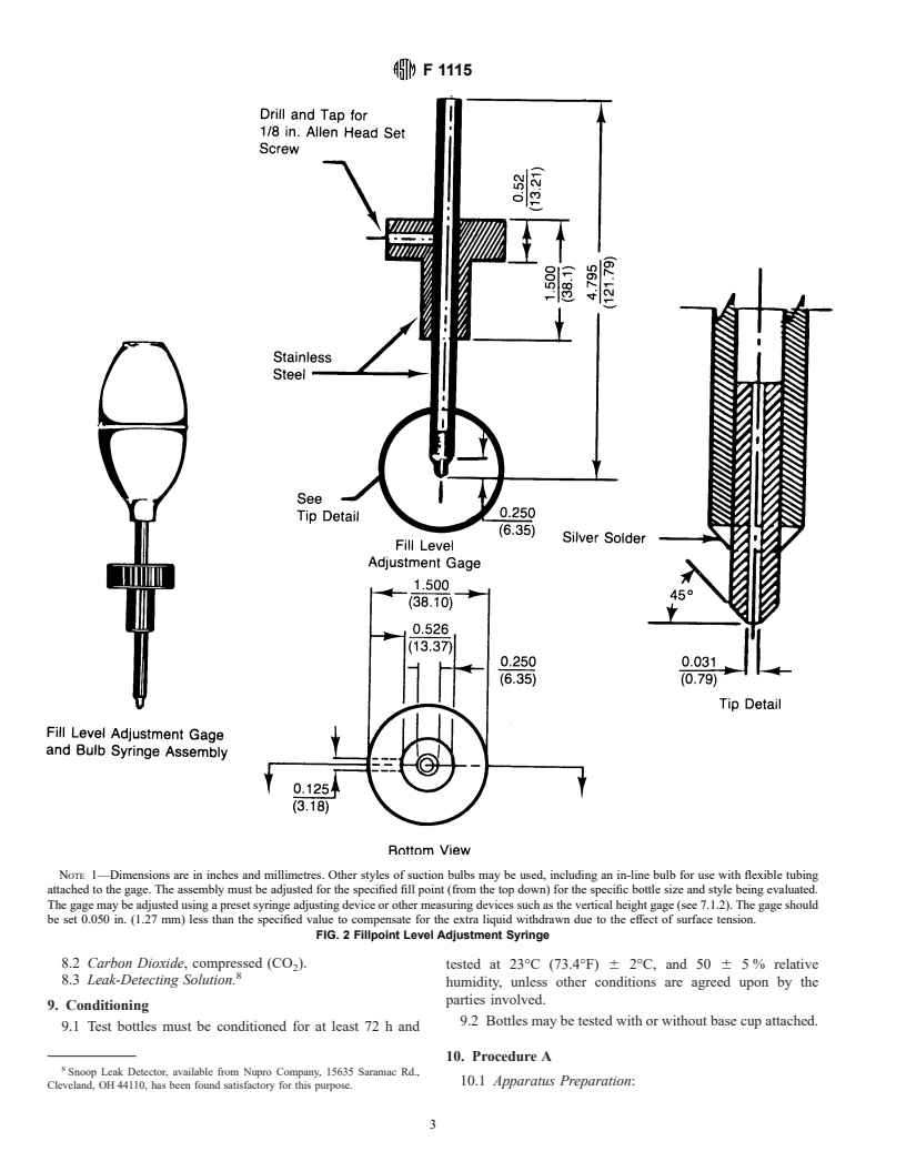
NOTE 1—Dimensions are in inches and millimetres. Other styles of suction bulbs may be used, including an in-line bulb for use with flexible tubing
attached to the gage. The assembly must be adjusted for the specified fill point (from the top down) for the specific bottle size and style being evaluated.
The gage may be adjusted using a preset syringe adjusting device or other measuring devices such as the vertical height gage (see 7.1.2). The gage should
be set 0.050 in. (1.27 mm) less than the specified value to compensate for the extra liquid withdrawn due to the effect of surface tension.
FIG. 2 Fillpoint Level Adjustment Syringe
8.2 Carbon Dioxide, compressed (CO ).
2 tested at 23°C (73.4°F) 6 2°C, and 50 6 5 % relative
8.3 Leak-Detecting Solution.
humidity, unless other conditions are agreed upon by the
parties involved.
9. Conditioning
9.2 Bottles may be tested with or without base cup attached.
9.1 Test bottles must be conditioned for at least 72 h and
10. Procedure A
Snoop Leak Detector, available from Nupro Company, 15635 Saramac Rd.,
10.1 Apparatus Preparation:
Cleveland, OH 44110, has been found satisfactory for this purpose.
F 1115
10.1.1 Assemble and calibrate pressure- and temperature- determine the quality of the material distribution (optional).
monitoring equipment.
10.5.2 Twenty-four hours after filling, agitate each test
10.1.2 Pressure test assembly at 60 psi using leak detecting
bottle to equilibrium pressure for at least 1 min to obtain the
solution.
initial values as outlined below:
10.1.3 Check calibration of monitoring equipment.
10.5.2.1 Equilibrium pressure of each bottle,
10.2 Record weight and dimensions of empty and filled
10.5.2.2 Temperature of each bottle or the control bottles,
bottles (optional).
10.5.2.3 Carbonation level (from a carbonation volumes
10.2.1 Weigh each empty bottle to at least 0.
...
Questions, Comments and Discussion
Ask us and Technical Secretary will try to provide an answer. You can facilitate discussion about the standard in here.
Loading comments...