


ASTM E457-08(2015)
(Test Method)Standard Test Method for Measuring Heat-Transfer Rate Using a Thermal Capacitance (Slug) Calorimeter
Standard Test Method for Measuring Heat-Transfer Rate Using a Thermal Capacitance (Slug) Calorimeter
SIGNIFICANCE AND USE
4.1 The purpose of this test method is to measure the rate of thermal energy per unit area transferred into a known piece of material (slug) for purposes of calibrating the thermal environment into which test specimens are placed for evaluation. The calorimeter and holder size and shape should be identical to that of the test specimen. In this manner, the measured heat transfer rate to the calorimeter can be related to that experienced by the test specimen.
4.2 The slug calorimeter is one of many calorimeter concepts used to measure heat transfer rate. This type of calorimeter is simple to fabricate, inexpensive, and readily installed since it is not water-cooled. The primary disadvantages are its short lifetime and relatively long cool-down time after exposure to the thermal environment. In measuring the heat transfer rate to the calorimeter, accurate measurement of the rate of rise in back-face temperature is imperative.
4.3 In the evaluation of high-temperature materials, slug calorimeters are used to measure the heat transfer rate on various parts of the instrumented models, since heat transfer rate is one of the important parameters in evaluating the performance of ablative materials.
4.4 Regardless of the source of thermal energy to the calorimeter (radiative, convective, or a combination thereof) the measurement is averaged over the calorimeter surface. If a significant percentage of the total thermal energy is radiative, consideration should be given to the emissivity of the slug surface. If non-uniformities exist in the input energy, the heat transfer rate calorimeter would tend to average these variations; therefore, the size of the sensing element (that is, the slug) should be limited to small diameters in order to measure local heat transfer rate values. Where large ablative samples are to be tested, it is recommended that a number of calorimeters be incorporated in the body of the test specimen such that a heat transfer rate distribution across...
SCOPE
1.1 This test method describes the measurement of heat transfer rate using a thermal capacitance-type calorimeter which assumes one-dimensional heat conduction into a cylindrical piece of material (slug) with known physical properties.
1.2 The values stated in SI units are to be regarded as standard. No other units of measurement are included in this standard.
Note 1: For information see Test Methods E285, E422, E458, E459, and E511.
1.3 This standard does not purport to address all of the safety concerns, if any, associated with its use. It is the responsibility of the user of this standard to establish appropriate safety and health practices and determine the applicability of regulatory limitations prior to use.
General Information
Buy Standard
Standards Content (Sample)
NOTICE: This standard has either been superseded and replaced by a new version or withdrawn.
Contact ASTM International (www.astm.org) for the latest information
Designation: E457 − 08 (Reapproved 2015)
Standard Test Method for
Measuring Heat-Transfer Rate Using a Thermal Capacitance
(Slug) Calorimeter
This standard is issued under the fixed designation E457; the number immediately following the designation indicates the year of
original adoption or, in the case of revision, the year of last revision.Anumber in parentheses indicates the year of last reapproval.A
superscript epsilon (´) indicates an editorial change since the last revision or reapproval.
1. Scope 3.1.1 Density and specific heat of the slug material,
3.1.2 Length or axial distance from the front face of the
1.1 This test method describes the measurement of heat
cylindrical slug to the back-face thermocouple,
transfer rate using a thermal capacitance-type calorimeter
3.1.3 Slope of the temperature—time curve generated by
which assumes one-dimensional heat conduction into a cylin-
the back-face thermocouple, and
drical piece of material (slug) with known physical properties.
3.1.4 Calorimeter temperature history.
1.2 The values stated in SI units are to be regarded as
standard. No other units of measurement are included in this
3.2 The heat transfer rate is thus determined numerically by
standard.
multiplyingthedensity,specificheat,andlengthoftheslugby
the slope of the temperature–time curve obtained by the data
NOTE 1—For information see Test Methods E285, E422, E458, E459,
acquisition system (see Eq 1).
and E511.
1.3 This standard does not purport to address all of the
3.3 The technique for measuring heat transfer rate by the
safety concerns, if any, associated with its use. It is the
thermal capacitance method is illustrated schematically in Fig.
responsibility of the user of this standard to establish appro-
1.Theapparatusshownisatypicalslugcalorimeterwhich,for
priate safety and health practices and determine the applica-
example, can be used to determine both stagnation region heat
bility of regulatory limitations prior to use.
transfer rate and side-wall or afterbody heat transfer rate
values.Theannularinsulatorservesthepurposeofminimizing
2. Referenced Documents
heat transfer to or from the body of the calorimeter, thus
2.1 ASTM Standards:
approximating one-dimensional heat flow. The body of the
E285Test Method for Oxyacetylene Ablation Testing of
calorimeter is configured to establish flow and should have the
Thermal Insulation Materials
same size and shape as that used for ablation models or test
E422Test Method for Measuring Heat Flux Using a Water-
specimens.
Cooled Calorimeter
3.3.1 For the control volume specified in this test method, a
E458Test Method for Heat of Ablation
thermal energy balance during the period of initial linear
E459Test Method for Measuring Heat Transfer Rate Using
temperatureresponsewhereheatlossesareassumednegligible
a Thin-Skin Calorimeter
can be stated as follows:
E511TestMethodforMeasuringHeatFluxUsingaCopper-
EnergyReceivedbytheCalorimeter ~frontface!
Constantan Circular Foil, Heat-Flux Transducer
5EnergyConductedAxiallyIntotheSlug
3. Summary of Test Method
q 5 ρC l ∆T/∆τ 5 MC /A ∆T/∆τ (1)
~ ! ~ !~ !
c p p
3.1 The measurement of heat transfer rate to a slug or
where:
thermal capacitance type calorimeter may be determined from
q˙ = calorimeter heat transfer rate, W/m ,
c
the following data:
ρ = density of slug material, kg/m ,
C = average specific heat of slug material during the
p
temperature rise (∆T), J/kg·K,
This test method is under the jurisdiction of ASTM Committee E21 on Space
Simulation andApplications of SpaceTechnology and is the direct responsibility of
l = length or axial distance from front face of slug to the
Subcommittee E21.08 on Thermal Protection.
thermocouple location (back-face), m,
Current edition approved May 1, 2015. Published June 2015. Originally
∆T =(T − T)=calorimeter slug temperature rise during
f i
approved in 1972. Last previous edition approved in 2008 as E457–08. DOI:
exposure to heat source (linear part of curve), K,
10.1520/E0457-08R15.
For referenced ASTM standards, visit the ASTM website, www.astm.org, or ∆τ =(τ − τ)=timeperiodcorrespondingto∆Ttemperature
f i
contact ASTM Customer Service at service@astm.org. For Annual Book of ASTM
rise, s,
Standards volume information, refer to the standard’s Document Summary page on
M = mass of the cylindrical slug, kg,
the ASTM website.
Copyright © ASTM International, 100 Barr Harbor Drive, PO Box C700, West Conshohocken, PA 19428-2959. United States
E457 − 08 (Reapproved 2015)
A = cross-sectional area of slug, m .
E457 − 08 (2015)
FIG. 1 Schematic of a Thermal Capacitance (Slug) Calorimeter
In order to determine the steady-state heat transfer rate with possible decaying processes such as a drop in surface
athermalcapacitance-typecalorimeter,Eq1mustbesolvedby catalycity, can cause the Temperature-Time slope to decrease
using the known properties of the slug material (for example, significantly more than can be accounted for by the increasing
densityandspecificheat)—thelengthoftheslug,andtheslope heat capacity with temperature of the Copper slug alone,
(linear portion) of the temperature–time curve obtained during makingitimportantthattheslopebetakenearlyintheprocess
the exposure to a heat source.The initial and final temperature before the losses lower the slope too much, introducing more
transient effects must be eliminated by using the initial linear error to the downside on the heat flux calculated (see Fig. 3).
portion of the curve (see Fig. 2). The degree of losses affect the exact position where the best
3.3.2 In order to calculate the initial response time for a slope begins to occur, but typically it should be expected at
given slug, Eq 2 may be used. This equation is based on the about time τ = τ calculated by Eq 2 for q /q = 0.99,
R indicated input
idealization of zero heat losses from slug to its holder. which value of τ is abbreviated as τ . Fig. 2 and Fig. 3
R R0.99
assume that “heat source on” is a step function. This is an
l ρC 2
p
τ 5 ln (2)
idealization, but the reality can be significantly different. For
R 2
kπ q indicated
S D
1 2
example, in some cases a calorimeter may experience a higher
q input
heat flux prior to reaching its final position in the heat source,
where:
which can cause the initial maximum slope to be higher than
k = thermal conductivity of slug material, W/m·K what is wanted for the calculation of the heat flux at the final
q = q that would be measured at the back-face of the position. Therefore, it is important to note that “zero” time, to
indicated
slug by Eq 1, W/m
which τ is added to determine where to start looking for
R0.99
q = constant q at the front-face of the slug begin-
the desired slope, is when the calorimeter has reached its final
input input
ning at τ = 0, W/m
positionwhereitisdesiredtomeasuretheheatflux.Therefore,
choosingthebestplacetotaketheslopecanbeveryimportant.
3.3.3 Although the goal of good slug calorimeter design is
Should more accurate results be required, the losses form the
to minimize heat losses, there can be heating environments,
slugshouldbemodeledandaccountedforbyacorrectionterm
such as very high heat fluxes, where even a good slug
in the energy balance equation.
calorimeter design cannot meet the recommended 5 % maxi-
3.3.4 For maximum linear test time (temperature–time
mum heat loss criterion of 6.1. Also, this criterion only deals
curve)withinanallowedsurfacetemperaturelimit,therelation
with heat losses measured during the cooling phase, not losses
shownasEq3maybeusedforacalorimeterwhichisinsulated
duringtheheatingphase,whichcanbegreaterthanthecooling
by a gap at the back face.
losses. Under these circumstances, significant heat losses from
slug to holder during the heating phase, as well as other
τ 50.48ρlC ~∆T /q˙ ! (3)
max,opt. p frontface
“Thermophysical Properties of High Temperature Solid Materials,” TPRC, Childs, P. R. N., Greenwood, J. R., and Long, C. A., “Heat flux measurement
Purdue University, or “Handbook of Thermophysical Properties,” Tolukian and techniques,” Proceedings of the Institution of Mechanical Engineers, Vol 213, Part
Goldsmith, MacMillan Press, 1961. C, 1999, pp. 664–665.
4 6
Ledford, R. L., Smotherman,W. E., and Kidd, C.T., “Recent Developments in Kirchhoff, R. H., “Calorimetric Heating-Rate Probe for Maximum-Response-
Heat-Transfer Rate, Pressure, and Force Measurements for Hotshot Tunnels,” TimeInterval,” American Institute ofAeronautics andAstronautics Journal,AIAJA,
AEDC-TR-66-228 (AD645764), January 1967. Vol 2, No. 5, May 1964, pp. 966–67.
E457 − 08 (2015)
FIG. 2 Typical Temperature–Time Curve for Slug Calorimeter
FIG. 3 Temperature–Time Curve when Heat and Other Items are Significant During Heating Phase
E457 − 08 (2015)
where: surface. If non-uniformities exist in the input energy, the heat
transfer rate calorimeter would tend to average these varia-
∆T = the calorimeter final front face temperature
front face
tions; therefore, the size of the sensing element (that is, the
minus the initial front face (ambient)
slug) should be limited to small diameters in order to measure
temperature, T .
o
localheattransferratevalues.Wherelargeablativesamplesare
3.3.5 Eq3isbasedontheoptimumlengthoftheslugwhich
to be tested, it is recommended that a number of calorimeters
can be obtained by applying Eq 4 as follows:
be incorporated in the body of the test specimen such that a
l 53 k ∆T /5q˙ (4)
opt. frontface c heat transfer rate distribution across the heated surface can be
determined. In this manner, more representative heat transfer
3.4 Tominimizesideheatingorsideheatlosses,thebodyis
ratevaluescanbedefinedforthetestspecimenandthusenable
separated physically from the calorimeter slug by means of an
more meaningful interpretation of the test. The slug selection
insulating gap or a low thermal diffusivity material, or both.
may be determined using the nomogram as a guide (see
The insulating gap that is employed should be small, and
Appendix X1).
recommendedtobenomorethan0.05mmontheradius.Thus,
if severe pressure vari
...
This document is not an ASTM standard and is intended only to provide the user of an ASTM standard an indication of what changes have been made to the previous version. Because
it may not be technically possible to adequately depict all changes accurately, ASTM recommends that users consult prior editions as appropriate. In all cases only the current version
of the standard as published by ASTM is to be considered the official document.
Designation: E457 − 08 E457 − 08 (Reapproved 2015)
Standard Test Method for
Measuring Heat-Transfer Rate Using a Thermal Capacitance
(Slug) Calorimeter
This standard is issued under the fixed designation E457; the number immediately following the designation indicates the year of
original adoption or, in the case of revision, the year of last revision. A number in parentheses indicates the year of last reapproval. A
superscript epsilon (´) indicates an editorial change since the last revision or reapproval.
1. Scope
1.1 This test method describes the measurement of heat transfer rate using a thermal capacitance-type calorimeter which
assumes one-dimensional heat conduction into a cylindrical piece of material (slug) with known physical properties.
1.2 This standard does not purport to address all of the safety concerns, if any, associated with its use. It is the responsibility
of the user of this standard to establish appropriate safety and health practices and determine the applicability of regulatory
limitations prior to use.
1.2 The values stated in SI units are to be regarded as standard. No other units of measurement are included in this standard.
NOTE 1—For information see Test Methods E285, E422, E458, E459, and E511.
1.3 This standard does not purport to address all of the safety concerns, if any, associated with its use. It is the responsibility
of the user of this standard to establish appropriate safety and health practices and determine the applicability of regulatory
limitations prior to use.
2. Referenced Documents
2.1 ASTM Standards:
E285 Test Method for Oxyacetylene Ablation Testing of Thermal Insulation Materials
E422 Test Method for Measuring Heat Flux Using a Water-Cooled Calorimeter
E458 Test Method for Heat of Ablation
E459 Test Method for Measuring Heat Transfer Rate Using a Thin-Skin Calorimeter
E511 Test Method for Measuring Heat Flux Using a Copper-Constantan Circular Foil, Heat-Flux Transducer
3. Summary of Test Method
3.1 The measurement of heat transfer rate to a slug or thermal capacitance type calorimeter may be determined from the
following data:
3.1.1 Density and specific heat of the slug material,
3.1.2 Length or axial distance from the front face of the cylindrical slug to the back-face thermocouple,
3.1.3 Slope of the temperature—time curve generated by the back-face thermocouple, and
3.1.4 Calorimeter temperature history.
3.2 The heat transfer rate is thus determined numerically by multiplying the density, specific heat, and length of the slug by the
slope of the temperature–time curve obtained by the data acquisition system (see Eq 1).
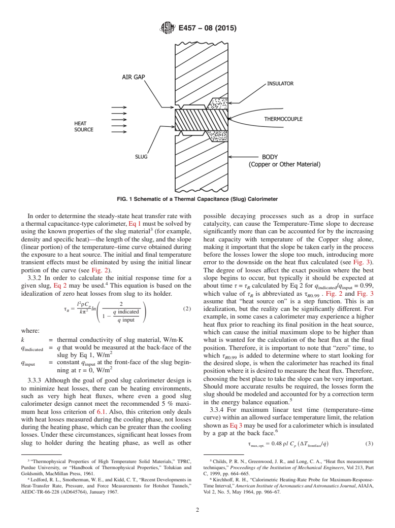
3.3 The technique for measuring heat transfer rate by the thermal capacitance method is illustrated schematically in Fig. 1. The
apparatus shown is a typical slug calorimeter which, for example, can be used to determine both stagnation region heat transfer
rate and side-wall or afterbody heat transfer rate values. The annular insulator serves the purpose of minimizing heat transfer to
or from the body of the calorimeter, thus approximating one-dimensional heat flow. The body of the calorimeter is configured to
establish flow and should have the same size and shape as that used for ablation models or test specimens.
This test method is under the jurisdiction of ASTM Committee E21 on Space Simulation and Applications of Space Technology and is the direct responsibility of
Subcommittee E21.08 on Thermal Protection.
Current edition approved May 1, 2008May 1, 2015. Published June 2008June 2015. Originally approved in 1972. Last previous edition approved in 20022008 as E457 – 96
(2002).E457 – 08. DOI: 10.1520/E0457-08.10.1520/E0457-08R15.
For referenced ASTM standards, visit the ASTM website, www.astm.org, or contact ASTM Customer Service at service@astm.org. For Annual Book of ASTM Standards
volume information, refer to the standard’s Document Summary page on the ASTM website.
Copyright © ASTM International, 100 Barr Harbor Drive, PO Box C700, West Conshohocken, PA 19428-2959. United States
E457 − 08 (2015)
FIG. 1 Schematic of a Thermal Capacitance (Slug) Calorimeter
3.3.1 For the control volume specified in this test method, a thermal energy balance during the period of initial linear
temperature response where heat losses are assumed negligible can be stated as follows:
Energy Received by the Calorimeter front face 5Energy Conducted Axially Into the Slug
~ !
q 5 ρC l ΔT/Δτ 5 MC /A ΔT/Δτ (1)
~ ! ~ ! ~ !
c p p
where:
q˙ = calorimeter heat transfer rate, W/m ,
c
ρ = density of slug material, kg/m ,
C = average specific heat of slug material during the temperature rise (ΔT), J/kg·K,
p
l = length or axial distance from front face of slug to the thermocouple location (back-face), m,
ΔT = (T − T ) = calorimeter slug temperature rise during exposure to heat source (linear part of curve), K,
f i
Δτ = (τ − τ ) = time period corresponding to ΔT temperature rise, s,
f i
M = mass of the cylindrical slug, kg,
A = cross-sectional area of slug, m .
In order to determine the steady-state heat transfer rate with a thermal capacitance-type calorimeter, Eq 1 must be solved by
using the known properties of the slug material (for example, density and specific heat)—the length of the slug, and the slope
(linear portion) of the temperature–time curve obtained during the exposure to a heat source. The initial and final temperature
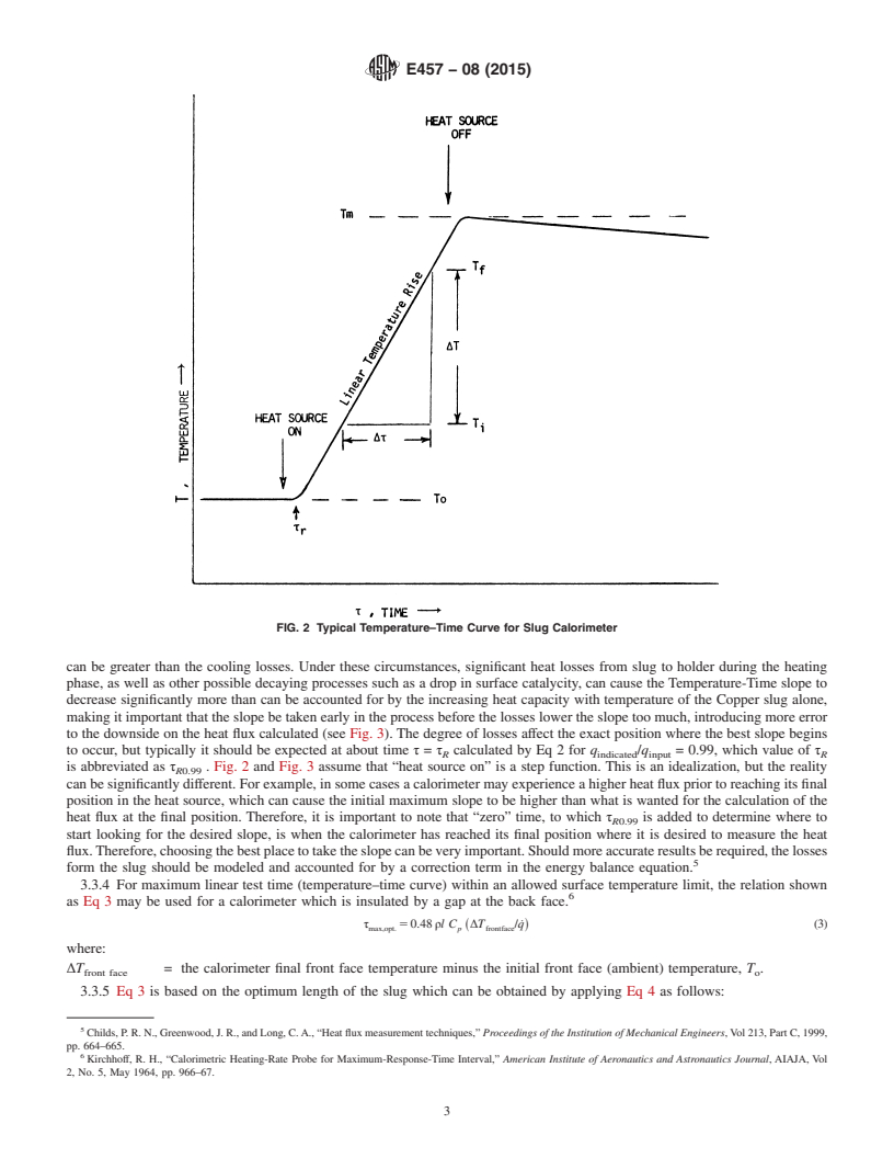
transient effects must be eliminated by using the initial linear portion of the curve (see Fig. 2).
3.3.2 In order to calculate the initial response time for a given slug, Eq 2 may be used. This equation is based on the idealization
of zero heat losses from slug to its holder.
l ρC 2
p
τ 5 ln (2)
R 2
kπ q indicated
S D
q input
where:
k = thermal conductivity of slug material, W/m·K
q = q that would be measured at the back-face of the slug by Eq 1, W/m
indicated
q = constant q at the front-face of the slug beginning at τ = 0, W/m
input input
3.3.3 Although the goal of good slug calorimeter design is to minimize heat losses, there can be heating environments, such as
very high heat fluxes, where even a good slug calorimeter design cannot meet the recommended 5 % maximum heat loss criterion
of 6.1. Also, this criterion only deals with heat losses measured during the cooling phase, not losses during the heating phase, which
“Thermophysical Properties of High Temperature Solid Materials,” TPRC, Purdue University, or “Handbook of Thermophysical Properties,” Tolukian and Goldsmith,
MacMillan Press, 1961.
Ledford, R. L., Smotherman, W. E., and Kidd, C. T., “Recent Developments in Heat-Transfer Rate, Pressure, and Force Measurements for Hotshot Tunnels,”
AEDC-TR-66-228 (AD645764), January 1967.
E457 − 08 (2015)
FIG. 2 Typical Temperature–Time Curve for Slug Calorimeter
can be greater than the cooling losses. Under these circumstances, significant heat losses from slug to holder during the heating
phase, as well as other possible decaying processes such as a drop in surface catalycity, can cause the Temperature-Time slope to
decrease significantly more than can be accounted for by the increasing heat capacity with temperature of the Copper slug alone,
making it important that the slope be taken early in the process before the losses lower the slope too much, introducing more error
to the downside on the heat flux calculated (see Fig. 3). The degree of losses affect the exact position where the best slope begins
to occur, but typically it should be expected at about time τ = τ calculated by Eq 2 for q /q = 0.99, which value of τ
R indicated input R
is abbreviated as τ . Fig. 2 and Fig. 3 assume that “heat source on” is a step function. This is an idealization, but the reality
R0.99
can be significantly different. For example, in some cases a calorimeter may experience a higher heat flux prior to reaching its final
position in the heat source, which can cause the initial maximum slope to be higher than what is wanted for the calculation of the
heat flux at the final position. Therefore, it is important to note that “zero” time, to which τ is added to determine where to
R0.99
start looking for the desired slope, is when the calorimeter has reached its final position where it is desired to measure the heat
flux. Therefore, choosing the best place to take the slope can be very important. Should more accurate results be required, the losses
form the slug should be modeled and accounted for by a correction term in the energy balance equation.
3.3.4 For maximum linear test time (temperature–time curve) within an allowed surface temperature limit, the relation shown
as Eq 3 may be used for a calorimeter which is insulated by a gap at the back face.
τ 5 0.48 ρl C ΔT /q˙ (3)
~ !
max,opt. p frontface
where:
ΔT = the calorimeter final front face temperature minus the initial front face (ambient) temperature, T .
front face o
3.3.5 Eq 3 is based on the optimum length of the slug which can be obtained by applying Eq 4 as follows:
Childs, P. R. N., Greenwood, J. R., and Long, C. A., “Heat flux measurement techniques,” Proceedings of the Institution of Mechanical Engineers, Vol 213, Part C, 1999,
pp. 664–665.
Kirchhoff, R. H., “Calorimetric Heating-Rate Probe for Maximum-Response-Time Interval,” American Institute of Aeronautics and Astronautics Journal, AIAJA, Vol
2, No. 5, May 1964, pp. 966–67.
E457 − 08 (2015)
FIG. 3 Temperature–Time Curve when Heat and Other Items are Significant During Heating Phase
l 5 3 k ΔT /5q˙ (4)
opt. front face c
3.4 To minimize side heating or side heat losses, the body is separated physically from the calorimeter slug by means of an
insulating gap or a low thermal diffusivity material, or both. The insulating gap that is employed should be small, and
recommended to be no more than 0.05 mm on the radius. Thus, if severe pressure variations exist across the face of the calorimeter,
side heating caused by flow into or out of the insulation gap would be minimized. Depending on the size of the calorimeter surface,
variations in heat transfer rate may exist across the face of the calorimeter; therefore, the measured heat transfer rate represents
an average heat transfer rate over the surface of the slug.
3.5 Since interpretation of the data obtained by this test method is not within the scope of this discussi
...
Questions, Comments and Discussion
Ask us and Technical Secretary will try to provide an answer. You can facilitate discussion about the standard in here.