


ASTM E2268-04(2016)
(Test Method)Standard Test Method for Water Penetration of Exterior Windows, Skylights, and Doors by Rapid Pulsed Air Pressure Difference
Standard Test Method for Water Penetration of Exterior Windows, Skylights, and Doors by Rapid Pulsed Air Pressure Difference
SIGNIFICANCE AND USE
5.1 This test method is a standard procedure for determining the resistance to water penetration during rapid cyclic pulses of dynamic air pressure differences. The air-pressure differences acting across a building envelope vary greatly. These factors should be fully considered prior to specifying the test pressure difference to be used.
5.2 The median test pressure used in this test method is defined as the specified test pressure supplied by the user and related to the maximum positive building design pressure. This test method departs from the format of other ASTM water penetration resistance test methods based on a maximum test pressure related to a maximum positive building design pressure.
5.3 As the specified or median test pressure is increased, the maximum test pressure in this procedure is also increased to 1.5 times the specification median test pressure. This higher maximum test pressure may not be representative of actual building service conditions. For this reason the maximum recommended median test pressure is 480 Pa (10 psf), which corresponds to a maximum test pressure of 720 Pa (15 psf).
5.4 The pulsed pressure of this test method may act to pump water past dry seals and breather systems of units incorporating these features, thereby making the test method more severe than a static pressure test method. On the other hand, the low pressure portions of the pressure cycles of this test method may allow weep systems and drainage dams to dissipate water from units incorporating these features, thereby making the test method less severe than a static pressure test method.
Note 1: In applying the results of tests by this test method, note that the performance of a wall or its components, or both, may be a function of proper installation and adjustment. In service, the performance will also depend on the rigidity of supporting construction and on the resistance of components to deterioration by various causes, (vibration, thermal expansion and ...
SCOPE
1.1 This test method covers the determination of the resistance of exterior windows, skylights, and doors to water penetration when water is applied to the outdoor face and exposed edges simultaneously with a rapid pulsed air pressure at the outdoor face higher than the pressure at the indoor face.
1.2 This test method is applicable to windows, skylights, or doors alone. Those interested in testing curtain walls to rapid pulsed air pressure differences should use AAMA 501.1-94.
1.3 This test method addresses water penetration through a manufactured assembly. Water that penetrates the assembly, but does not result in a failure as defined herein, may have adverse effects on the performance of contained materials such as sealants and insulating or laminated glass. This test method does not address these issues.
1.4 The proper use of this test method requires a knowledge of the principles of pressure measurement.
1.5 The values stated in SI units are to be regarded as standard. The values given in parentheses are mathematical conversions to inch-pound units that are provided for information only and are not considered standard.
1.6 This standard does not purport to address all of the safety concerns, if any, associated with its use. It is the responsibility of the user of this standard to establish appropriate safety and health practices and determine the applicability of regulatory limitations prior to use.
General Information
Buy Standard


Standards Content (Sample)
NOTICE: This standard has either been superseded and replaced by a new version or withdrawn.
Contact ASTM International (www.astm.org) for the latest information
Designation: E2268 − 04 (Reapproved 2016)
Standard Test Method for
Water Penetration of Exterior Windows, Skylights, and
Doors by Rapid Pulsed Air Pressure Difference
This standard is issued under the fixed designation E2268; the number immediately following the designation indicates the year of
original adoption or, in the case of revision, the year of last revision. A number in parentheses indicates the year of last reapproval. A
superscript epsilon (´) indicates an editorial change since the last revision or reapproval.
1. Scope 2.2 AAMA Standard:
AAMA 501.1-94 Standard Test Method for Exterior
1.1 This test method covers the determination of the resis-
Windows, Curtain Walls and Doors for Water Penetration
tance of exterior windows, skylights, and doors to water
Using Dynamic Pressure
penetration when water is applied to the outdoor face and
exposed edges simultaneously with a rapid pulsed air pressure
3. Terminology
at the outdoor face higher than the pressure at the indoor face.
3.1 Definitions—For definitions of general terms relating to
1.2 This test method is applicable to windows, skylights, or
building construction used in this test method, see Terminology
doors alone. Those interested in testing curtain walls to rapid
E631.
pulsed air pressure differences should use AAMA 501.1-94.
3.2 Definitions of Terms Specific to This Standard:
1.3 This test method addresses water penetration through a
3.2.1 pulsed, v—subjected to a transition from one level of
manufactured assembly. Water that penetrates the assembly,
differential air pressure to another and back within a prescribed
but does not result in a failure as defined herein, may have
time period.
adverse effects on the performance of contained materials such
3.2.2 pulse generator, n—test apparatus capable of produc-
as sealants and insulating or laminated glass. This test method
ing rapid changes of air pressure between two prescribed levels
does not address these issues.
within a specified time period (see Fig. 3).
1.4 The proper use of this test method requires a knowledge
3.2.3 specimen, n—the entire assembled unit submitted for
of the principles of pressure measurement.
test as described in Section 8.
1.5 The values stated in SI units are to be regarded as
3.2.4 test pressure difference, n—the specified difference in
standard. The values given in parentheses are mathematical
dynamic air pressure across the closed and locked or fixed
conversions to inch-pound units that are provided for informa-
specimen expressed as Pascals (lbf/ft ).
tion only and are not considered standard.
3.2.5 water penetration, n—penetration of water beyond a
1.6 This standard does not purport to address all of the
plane parallel to the glazing intersecting the innermost projec-
safety concerns, if any, associated with its use. It is the
tion of the test specimen, not including interior trim and
responsibility of the user of this standard to establish appro-
hardware, under the specified conditions of air pressure differ-
priate safety and health practices and determine the applica-
ence across the specimen. For products with non-planar glaz-
bility of regulatory limitations prior to use.
ing surfaces (domes, vaults, pyramids, and so forth) the plane
defining water penetration is the plane defined by the innermost
2. Referenced Documents
edges of the unit frame.
2.1 ASTM Standards:
4. Summary of Test Method
E631 Terminology of Building Constructions
4.1 This test method consists of sealing the test specimen
into or against one face of a test chamber and supplying air to
or exhausting air from the chamber at a rapid cyclic rate across
This test method is under the jurisdiction of ASTM Committee E06 on
Performance of Buildings and is the direct responsibility of Subcommittee E06.51 the specimen for the time specified, while spraying water onto
on Performance of Windows, Doors, Skylights and Curtain Walls.
the outdoor face of the specimen at the required rate and
Current edition approved Aug. 1, 2016. Published August 2016. Originally
observing any water penetration.
approved in 2004. Last previous edition approved in 2011 as E2268 – 04(2011).
DOI: 10.1520/E2268-04R16.
For referenced ASTM standards, visit the ASTM website, www.astm.org, or
contact ASTM Customer Service at service@astm.org. For Annual Book of ASTM Available from American Architectural Manufacturers Association (AAMA),
Standards volume information, refer to the standard’s Document Summary page on 1827 Walden Office Square, Suite 550 Schaumburg, IL 60173-4268, http://
the ASTM website. www.aamanet.org.
Copyright © ASTM International, 100 Barr Harbor Drive, PO Box C700, West Conshohocken, PA 19428-2959. United States
E2268 − 04 (2016)
5. Significance and Use 6.2.2 Air System—A controllable blower, compressed air
supply, exhaust system, or reversible blower designed to
5.1 This test method is a standard procedure for determining
provide the required maximum air pressure difference across
the resistance to water penetration during rapid cyclic pulses of
the specimen. The system must provide fully reversible airflow
dynamic air pressure differences. The air-pressure differences
at rapidly oscillating pressures for the required test period.
acting across a building envelope vary greatly. These factors
6.2.3 Pressure Measuring Apparatus—A device to measure
should be fully considered prior to specifying the test pressure
the test pressure difference within a tolerance of 62 % or
difference to be used.
65 Pa (60.02 in. of water column), whichever is greater.
5.2 The median test pressure used in this test method is
6.2.4 Water Spray System—The water-spray system shall
defined as the specified test pressure supplied by the user and
deliver water uniformly against the exterior surface of the test
related to the maximum positive building design pressure. This
specimen at a minimum rate of 3.4 L/(m ·min) [5.0 U.S.
test method departs from the format of other ASTM water
gal/(ft ·h)].
penetration resistance test methods based on a maximum test
6.2.4.1 The water-spray system shall have nozzles spaced
pressure related to a maximum positive building design pres-
on a uniform grid, located at a uniform distance from the test
sure.
specimen, and shall be adjustable to provide the specified
5.3 As the specified or median test pressure is increased, the quantity of water in such a manner as to wet all of the test
specimen uniformly and to wet those areas vulnerable to water
maximum test pressure in this procedure is also increased to
1.5 times the specification median test pressure. This higher penetration. If additional nozzles are required to provide
uniformity of water spray at the edge of the test specimen, they
maximum test pressure may not be representative of actual
building service conditions. For this reason the maximum shall be equally spaced around the entire spray grid.
recommended median test pressure is 480 Pa (10 psf), which
7. Hazards
corresponds to a maximum test pressure of 720 Pa (15 psf).
7.1 Warning—Glass breakage will not normally occur at
5.4 The pulsed pressure of this test method may act to pump
the small pressure differences applied in this test. Excessive
water past dry seals and breather systems of units incorporating
pressure differences may occur, however, due to error in
these features, thereby making the test method more severe
operation or when the apparatus is used for other purposes such
than a static pressure test method. On the other hand, the low
as structural testing; therefore, exercise adequate precautions to
pressure portions of the pressure cycles of this test method may
protect personnel.
allow weep systems and drainage dams to dissipate water from
units incorporating these features, thereby making the test
8. Sampling, Test Specimens, and Test Units
method less severe than a static pressure test method.
NOTE 1—In applying the results of tests by this test method, note that
8.1 Test specimens shall be of sufficient size to determine
the performance of a wall or its components, or both, may be a function
the performance of all typical parts of the fenestration system.
of proper installation and adjustment. In service, the performance will also
8.1.1 Conditions of structural support shall be simulated as
depend on the rigidity of supporting construction and on the resistance of
components to deterioration by various causes, (vibration, thermal expan- accurately as possible.
sion and contraction, and so forth). It is difficult to accurately simulate the
8.2 Window, skylight, door, or other component test speci-
actual complex wetting conditions that can be encountered in service, with
mens shall consist of the entire assembled unit, including frame
large wind-blown water drops, increasing water drop impact pressures
with increasing wind velocity and lateral or upward moving air and water. and anchorage as supplied by the manufacturer for installation
Some designs are more sensitive than others to this upward moving water.
in the building.
NOTE 2—This test does not identify unobservable liquid water which
8.2.1 If only one specimen is to be tested, the selection shall
may penetrate into the test specimen.
be determined by the specifying authority.
6. Apparatus
NOTE 3—It should be recognized, especially with windows, that
performance is likely to be a function of size and geometry. Therefore,
6.1 The description of apparatus in this section is general in
select specimens covering the range of sizes to be used in a building. In
nature and any arrangement of equipment capable of perform-
general, the largest size of a particular design, type, construction, and
ing the test procedure within the allowable tolerances is
configuration to be used should be tested.
permitted.
9. Calibration and Standardization
6.2 Major Components (Fig. 1):
6.2.1 Test Chamber—A test chamber or box with an 9.1 The ability of the test apparatus to meet the require-
opening, a removable mounting panel, or one open side in ments of 6.2.4 shall be checked by using a catch box, the open
which or against which the specimen is installed and sealed. At face of which shall be located at the position of the face of the
least one dynamic pressure tap shall be provided
...
This document is not an ASTM standard and is intended only to provide the user of an ASTM standard an indication of what changes have been made to the previous version. Because
it may not be technically possible to adequately depict all changes accurately, ASTM recommends that users consult prior editions as appropriate. In all cases only the current version
of the standard as published by ASTM is to be considered the official document.
Designation: E2268 − 04 (Reapproved 2011) E2268 − 04 (Reapproved 2016)
Standard Test Method for
Water Penetration of Exterior Windows, Skylights, and
Doors by Rapid Pulsed Air Pressure Difference
This standard is issued under the fixed designation E2268; the number immediately following the designation indicates the year of
original adoption or, in the case of revision, the year of last revision. A number in parentheses indicates the year of last reapproval. A
superscript epsilon (´) indicates an editorial change since the last revision or reapproval.
1. Scope
1.1 This test method covers the determination of the resistance of exterior windows, skylights, and doors to water penetration
when water is applied to the outdoor face and exposed edges simultaneously with a rapid pulsed air pressure at the outdoor face
higher than the pressure at the indoor face.
1.2 This test method is applicable to windows, skylights, or doors alone. Those interested in testing curtain walls to rapid pulsed
air pressure differences should use AAMA 501.1-94.
1.3 This test method addresses water penetration through a manufactured assembly. Water that penetrates the assembly, but does
not result in a failure as defined herein, may have adverse effects on the performance of contained materials such as sealants and
insulating or laminated glass. This test method does not address these issues.
1.4 The proper use of this test method requires a knowledge of the principles of pressure measurement.
1.5 The values stated in SI units are to be regarded as standard. The values given in parentheses are mathematical conversions
to inch-pound units that are provided for information only and are not considered standard.
1.6 This standard does not purport to address all of the safety concerns, if any, associated with its use. It is the responsibility
of the user of this standard to establish appropriate safety and health practices and determine the applicability of regulatory
limitations prior to use.
2. Referenced Documents
2.1 ASTM Standards:
E631 Terminology of Building Constructions
2.2 AAMA Standard:
AAMA 501.1-94 Standard Test Method for Exterior Windows, Curtain Walls and Doors for Water Penetration Using Dynamic
Pressure
3. Terminology
3.1 Definitions—For definitions of general terms relating to building construction used in this test method, see Terminology
E631.
3.2 Definitions of Terms Specific to This Standard:
3.2.1 pulsed, v—subjected to a transition from one level of differential air pressure to another and back within a prescribed time
period.
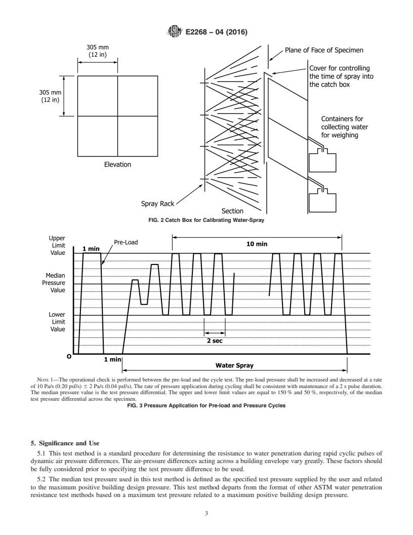
3.2.2 pulse generator, n—test apparatus capable of producing rapid changes of air pressure between two prescribed levels within
a specified time period (see Fig. 3).Fig. 3).
3.2.3 specimen, n—the entire assembled unit submitted for test as described in Section 8.
This test method is under the jurisdiction of ASTM Committee E06 on Performance of Buildings and is the direct responsibility of Subcommittee E06.51 on Performance
of Windows, Doors, Skylights and Curtain Walls.
Current edition approved Nov. 1, 2011Aug. 1, 2016. Published December 2011August 2016. Originally approved in 2004. Last previous edition approved in 20042011
as E2268 – 04.E2268 – 04(2011). DOI: 10.1520/E2268-04R11.10.1520/E2268-04R16.
For referenced ASTM standards, visit the ASTM website, www.astm.org, or contact ASTM Customer Service at service@astm.org. For Annual Book of ASTM Standards
volume information, refer to the standard’s Document Summary page on the ASTM website.
Available from American Architectural Manufacturers Association (AAMA), 1827 Walden Office Square, Suite 550 Schaumburg, IL 60173,60173-4268, http://
www.aamanet.org.
Copyright © ASTM International, 100 Barr Harbor Drive, PO Box C700, West Conshohocken, PA 19428-2959. United States
E2268 − 04 (2016)
NOTE 1—For a negative pressure system, the water-spray grid would be located outside the chamber and the air supply would be replaced by an
air-exhaust system.
FIG. 1 General Arrangement of the Water Leakage Apparatus Positive Chamber System
3.2.4 test pressure difference, n—the specified difference in dynamic air pressure across the closed and locked or fixed specimen
expressed as Pascals (lbf/ft ).
3.2.5 water penetration, n—penetration of water beyond a plane parallel to the glazing intersecting the innermost projection of
the test specimen, not including interior trim and hardware, under the specified conditions of air pressure difference across the
specimen. For products with non-planar glazing surfaces (domes, vaults, pyramids, and so forth) the plane defining water
penetration is the plane defined by the innermost edges of the unit frame.
4. Summary of Test Method
4.1 This test method consists of sealing the test specimen into or against one face of a test chamber and supplying air to or
exhausting air from the chamber at a rapid cyclic rate across the specimen for the time specified, while spraying water onto the
outdoor face of the specimen at the required rate and observing any water penetration.
E2268 − 04 (2016)
FIG. 2 Catch Box for Calibrating Water-Spray
NOTE 1—The operational check is performed between the pre-load and the cycle test. The pre-load pressure shall be increased and decreased at a rate
of 10 Pa/s (0.20 psf/s) 6 2 Pa/s (0.04 psf/s). The rate of pressure application during cycling shall be consistent with maintenance of a 2 s pulse duration.
The median pressure value is the test pressure differential. The upper and lower limit values are equal to 150 % and 50 %, respectively, of the median
test pressure differential across the specimen.
FIG. 3 Pressure Application for Pre-load and Pressure Cycles
5. Significance and Use
5.1 This test method is a standard procedure for determining the resistance to water penetration during rapid cyclic pulses of
dynamic air pressure differences. The air-pressure differences acting across a building envelope vary greatly. These factors should
be fully considered prior to specifying the test pressure difference to be used.
5.2 The median test pressure used in this test method is defined as the specified test pressure supplied by the user and related
to the maximum positive building design pressure. This test method departs from the format of other ASTM water penetration
resistance test methods based on a maximum test pressure related to a maximum positive building design pressure.
E2268 − 04 (2016)
5.3 As the specified or median test pressure is increased, the maximum test pressure in this procedure is also increased to 1.5
times the specification median test pressure. This higher maximum test pressure may not be representative of actual building
service conditions. For this reason the maximum recommended median test pressure is 480 Pa (10 psf), which corresponds to a
maximum test pressure of 720 Pa (15 psf).
5.4 The pulsed pressure of this test method may act to pump water past dry seals and breather systems of units incorporating
these features, thereby making the test method more severe than a static pressure test method. On the other hand, the low pressure
portions of the pressure cycles of this test method may allow weep systems and drainage dams to dissipate water from units
incorporating these features, thereby making the test method less severe than a static pressure test method.
NOTE 1—In applying the results of tests by this test method, note that the performance of a wall or its components, or both, may be a function of proper
installation and adjustment. In service, the performance will also depend on the rigidity of supporting construction and on the resistance of components
to deterioration by various causes, (vibration, thermal expansion and contraction, and so forth). It is difficult to accurately simulate the actual complex
wetting conditions that can be encountered in service, with large wind-blown water drops, increasing water drop impact pressures with increasing wind
velocity and lateral or upward moving air and water. Some designs are more sensitive than others to this upward moving water.
NOTE 2—This test does not identify unobservable liquid water which may penetrate into the test specimen.
6. Apparatus
6.1 The description of apparatus in this section is general in nature and any arrangement of equipment capable of performing
the test procedure within the allowable tolerances is permitted.
6.2 Major Components (Fig. 1):
6.2.1 Test Chamber—A test chamber or box with an opening, a removable mounting panel, or one open side in which or against
which the specimen is installed and sealed. At least one dynamic pressure tap shall be provided to measure the oscillating chamber
pressure, and shall be so located that the reading is unaffected by the velocity of the air supply to or from the chamber. The air
supply opening into the chamber shall be arranged so that the air does not impinge directly on the test specimen with any significant
velocity. A means of access into the chamber may be provided to facilitate adjustments and observations after the specimen has
been installed.
6.2.2 Air System—A controllable blower, compressed air supply, exhaust system, or reversible blower designed to provide the
required maximum air pressure difference across the specimen. The system must provide fully reversible airflow at rapidly
oscillating pressures for the required test period.
6.2.3 Pressure Measuring Apparatus—A device to measure the test pressure difference within a tolerance of 62 % or 65 Pa
65 Pa (60.02 in. of water column), whichever is greater.
6.2.4 Water Spray System—The water-spray system shall deliver water uniformly against the exterior surface of the test
2 2
specimen at a minimum rate of 3.4 L/(m ·min) [5.0 U.S. gal/(ft ·h)].
6.2.4.1 The water-spray system shall have nozzles spaced on a uniform grid, located at a uniform distance from the test
specimen, and shall be adjustable to provide the specified quantity of water in such a manner as to wet all of the test specimen
uniformly and to wet those areas vulnerable to water pe
...
Questions, Comments and Discussion
Ask us and Technical Secretary will try to provide an answer. You can facilitate discussion about the standard in here.