


ASTM C1341-13(2018)
(Test Method)Standard Test Method for Flexural Properties of Continuous Fiber-Reinforced Advanced Ceramic Composites
Standard Test Method for Flexural Properties of Continuous Fiber-Reinforced Advanced Ceramic Composites
SIGNIFICANCE AND USE
5.1 This test method is used for material development, quality control, and material flexural specifications. Although flexural test methods are commonly used to determine design strengths of monolithic advanced ceramics, the use of flexure test data for determining tensile or compressive properties of CFCC materials is strongly discouraged. The nonuniform stress distributions in the flexure test specimen, the dissimilar mechanical behavior in tension and compression for CFCCs, low shear strengths of CFCCs, and anisotropy in fiber architecture all lead to ambiguity in using flexure results for CFCC material design data (1-4).3 Rather, uniaxial-forced tensile and compressive tests are recommended for developing CFCC material design data based on a uniformly stressed test condition.
5.2 In this test method, the flexure stress is computed from elastic beam theory with the simplifying assumptions that the material is homogeneous and linearly elastic. This is valid for composites where the principal fiber direction is coincident/transverse with the axis of the beam. These assumptions are necessary to calculate a flexural strength value, but limit the application to comparative type testing such as used for material development, quality control, and flexure specifications. Such comparative testing requires consistent and standardized test conditions, that is, test specimen geometry/thickness, strain rates, and atmospheric/test conditions.
5.3 Unlike monolithic advanced ceramics which fracture catastrophically from a single dominant flaw, CFCCs generally experience “graceful” fracture from a cumulative damage process. Therefore, the volume of material subjected to a uniform flexural stress may not be as significant a factor in determining the flexural strength of CFCCs. However, the need to test a statistically significant number of flexure test specimens is not eliminated. Because of the probabilistic nature of the strength of the brittle matrices and of the ceramic...
SCOPE
1.1 This test method covers the determination of flexural properties of continuous fiber-reinforced ceramic composites in the form of rectangular bars formed directly or cut from sheets, plates, or molded shapes. Three test geometries are described as follows:
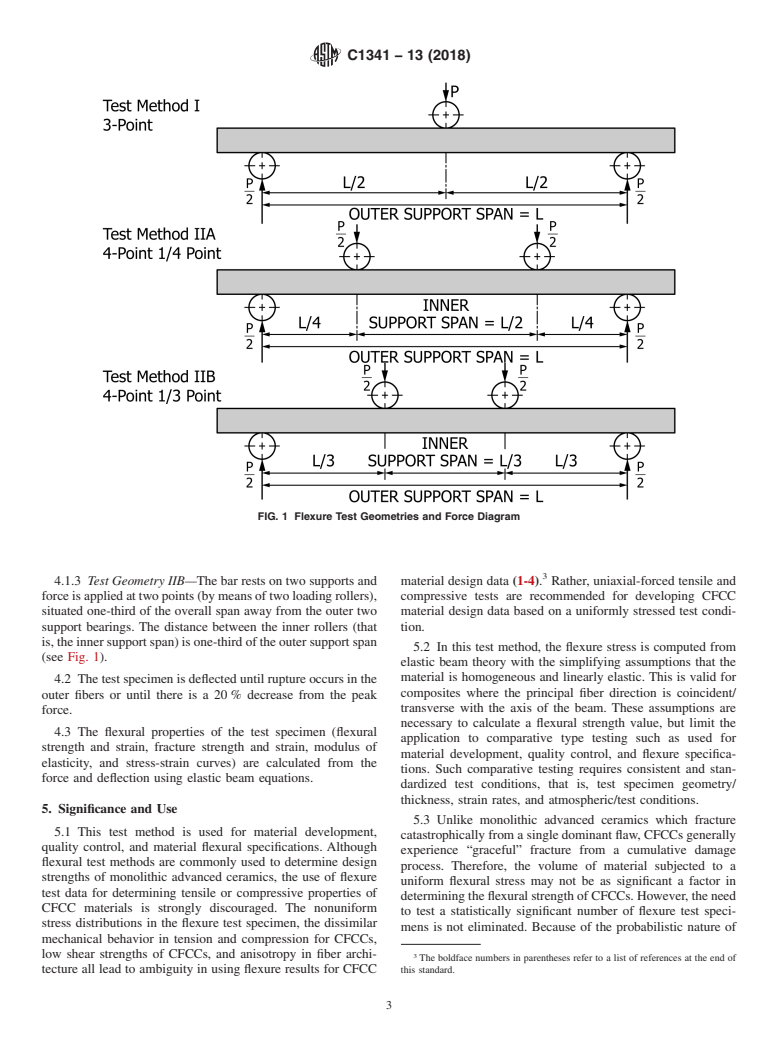
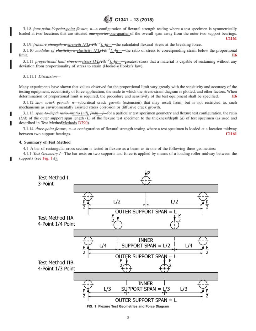
1.1.1 Test Geometry I—A three-point loading system utilizing center point force application on a simply supported beam.
1.1.2 Test Geometry IIA—A four-point loading system utilizing two force application points equally spaced from their adjacent support points, with a distance between force application points of one-half of the support span.
1.1.3 Test Geometry IIB—A four-point loading system utilizing two force application points equally spaced from their adjacent support points, with a distance between force application points of one-third of the support span.
1.2 This test method applies primarily to all advanced ceramic matrix composites with continuous fiber reinforcement: unidirectional (1D), bidirectional (2D), tridirectional (3D), and other continuous fiber architectures. In addition, this test method may also be used with glass (amorphous) matrix composites with continuous fiber reinforcement. However, flexural strength cannot be determined for those materials that do not break or fail by tension or compression in the outer fibers. This test method does not directly address discontinuous fiber-reinforced, whisker-reinforced, or particulate-reinforced ceramics. Those types of ceramic matrix composites are better tested in flexure using Test Methods C1161 and C1211.
1.3 Tests can be performed at ambient temperatures or at elevated temperatures. At elevated temperatures, a suitable furnace is necessary for heating and holding the test specimens at the desired testing temperatures.
1.4 This test method includes the following:
Section
Scope
1
Referenced Documents
2
Terminology
3
Summary of Test Method
...
General Information
Buy Standard

Standards Content (Sample)
NOTICE: This standard has either been superseded and replaced by a new version or withdrawn.
Contact ASTM International (www.astm.org) for the latest information
Designation: C1341 − 13 (Reapproved 2018)
Standard Test Method for
Flexural Properties of Continuous Fiber-Reinforced
Advanced Ceramic Composites
This standard is issued under the fixed designation C1341; the number immediately following the designation indicates the year of
original adoption or, in the case of revision, the year of last revision. A number in parentheses indicates the year of last reapproval. A
superscript epsilon (´) indicates an editorial change since the last revision or reapproval.
1. Scope*
Referenced Documents 2
Terminology 3
1.1 This test method covers the determination of flexural
Summary of Test Method 4
properties of continuous fiber-reinforced ceramic composites Significance and Use 5
Interferences 6
in the form of rectangular bars formed directly or cut from
Apparatus 7
sheets, plates, or molded shapes. Three test geometries are
Precautionary Statement 8
Test Specimens 9
described as follows:
Procedures 10
1.1.1 Test Geometry I—A three-point loading system utiliz-
Calculation of Results 11
ing center point force application on a simply supported beam.
Report 12
1.1.2 Test Geometry IIA—A four-point loading system uti- Precision and Bias 13
Keywords 14
lizing two force application points equally spaced from their
References
adjacent support points, with a distance between force appli-
CFCC Surface Condition and Finishing Annex A1
Conditions and Issues in Hot Loading of Test Annex A2
cation points of one-half of the support span.
Specimens into Furnaces
1.1.3 Test Geometry IIB—A four-point loading system uti-
Toe Compensation on Stress-Strain Curves Annex A3
lizing two force application points equally spaced from their
Corrections for Thermal Expansion in Flexural Annex A4
Equations
adjacent support points, with a distance between force appli-
Example of Test Report Appendix X1
cation points of one-third of the support span.
1.5 The values stated in SI units are to be regarded as the
1.2 This test method applies primarily to all advanced
standard in accordance with IEEE/ASTM SI 10.
ceramic matrix composites with continuous fiber reinforce-
1.6 This standard does not purport to address all of the
ment: unidirectional (1D), bidirectional (2D), tridirectional
safety concerns, if any, associated with its use. It is the
(3D), and other continuous fiber architectures. In addition, this
responsibility of the user of this standard to establish appro-
test method may also be used with glass (amorphous) matrix
priate safety, health, and environmental practices and deter-
composites with continuous fiber reinforcement. However,
mine the applicability of regulatory limitations prior to use.
flexural strength cannot be determined for those materials that
1.7 This international standard was developed in accor-
do not break or fail by tension or compression in the outer
dance with internationally recognized principles on standard-
fibers. This test method does not directly address discontinuous
ization established in the Decision on Principles for the
fiber-reinforced, whisker-reinforced, or particulate-reinforced
Development of International Standards, Guides and Recom-
ceramics. Those types of ceramic matrix composites are better
mendations issued by the World Trade Organization Technical
tested in flexure using Test Methods C1161 and C1211.
Barriers to Trade (TBT) Committee.
1.3 Tests can be performed at ambient temperatures or at
elevated temperatures. At elevated temperatures, a suitable
2. Referenced Documents
furnace is necessary for heating and holding the test specimens
2.1 ASTM Standards:
at the desired testing temperatures.
C1145 Terminology of Advanced Ceramics
1.4 This test method includes the following:
C1161 Test Method for Flexural Strength of Advanced
Section
Ceramics at Ambient Temperature
Scope 1
C1211 Test Method for Flexural Strength of Advanced
Ceramics at Elevated Temperatures
This test method is under the jurisdiction of ASTM Committee C28 on
Advanced Ceramics and is the direct responsibility of Subcommittee C28.07 on
Ceramic Matrix Composites. For referenced ASTM standards, visit the ASTM website, www.astm.org, or
Current edition approved July 1, 2018. Published July 2018. Originally approved contact ASTM Customer Service at service@astm.org. For Annual Book of ASTM
in 1996. Last previous edition approved in 2013 as C1341 – 13. DOI: 10.1520/ Standards volume information, refer to the standard’s Document Summary page on
C1341-13R18. the ASTM website.
*A Summary of Changes section appears at the end of this standard
Copyright © ASTM International, 100 Barr Harbor Drive, PO Box C700, West Conshohocken, PA 19428-2959. United States
C1341 − 13 (2018)
C1239 Practice for Reporting Uniaxial Strength Data and form a useful engineering material possessing certain proper-
Estimating Weibull Distribution Parameters for Advanced ties or behavior not possessed by the individual constituents.
Ceramics
3.1.5 continuous fiber-reinforced ceramic composite
C1292 Test Method for Shear Strength of Continuous Fiber-
(CFCC), n—ceramic matrix composite in which the reinforc-
Reinforced Advanced Ceramics at Ambient Temperatures
ing phase consists of a continuous fiber, continuous yarn, or a
D790 Test Methods for Flexural Properties of Unreinforced
woven fabric.
and Reinforced Plastics and Electrical Insulating Materi-
−2
3.1.6 flexural strength [FL ], n—measure of the ultimate
als
strength of a specified beam in bending. C1161
D2344/D2344M Test Method for Short-Beam Strength of
3.1.7 four-point- ⁄3-point flexure, n—a configuration of flex-
Polymer Matrix Composite Materials and Their Laminates
ural strength testing where a test specimen is symmetrically
D3878 Terminology for Composite Materials
loaded at two locations that are situated one-third of the overall
D6856/D6856M Guide for Testing Fabric-Reinforced “Tex-
span away from the outer two support bearings.
tile” Composite Materials
E4 Practices for Force Verification of Testing Machines 3.1.8 four-point- ⁄4-point flexure, n—a configuration of flex-
E6 Terminology Relating to Methods of Mechanical Testing
ural strength testing where a test specimen is symmetrically
E122 Practice for Calculating Sample Size to Estimate, With loaded at two locations that are situated one-quarter of the
Specified Precision, the Average for a Characteristic of a
overall span away from the outer two support bearings. C1161
−2
Lot or Process
3.1.9 fracture strength [FL ], n—the calculated flexural
E177 Practice for Use of the Terms Precision and Bias in
stress at the breaking force.
ASTM Test Methods
−2
3.1.10 modulus of elasticity [FL ], n—the ratio of stress to
E220 Test Method for Calibration of Thermocouples By
corresponding strain below the proportional limit. E6
Comparison Techniques
−2
3.1.11 proportional limit stress [FL ], n—greatest stress
E337 Test Method for Measuring Humidity with a Psy-
that a material is capable of sustaining without any deviation
chrometer (the Measurement of Wet- and Dry-Bulb Tem-
from proportionality of stress to strain (Hooke’s law).
peratures)
3.1.11.1 Discussion—Many experiments have shown that
E691 Practice for Conducting an Interlaboratory Study to
values observed for the proportional limit vary greatly with the
Determine the Precision of a Test Method
sensitivity and accuracy of the testing equipment, eccentricity
IEEE/ASTM SI 10 American National Standard for Use of
of force application, the scale to which the stress-strain
the International System of Units (SI): The Modern Metric
diagram is plotted, and other factors. When determination of
System
proportional limit is required, the procedure and sensitivity of
the test equipment shall be specified. E6
3. Terminology
3.1.12 slow crack growth, n—subcritical crack growth (ex-
3.1 Definitions:
tension) that may result from, but is not restricted to, such
3.1.1 The definitions of terms relating to flexure testing
mechanisms as environmentally assisted stress corrosion or
appearing in Terminology E6 apply to the terms used in this
diffusive crack growth.
test method. The definitions of terms relating to advanced
ceramics appearing in Terminology C1145 apply to the terms 3.1.13 span-to-depth ratio [nd], n—for a particular test
used in this test method. The definitions of terms relating to specimen geometry and flexure test configuration, the ratio
fiber-reinforced composites appearing in Terminology D3878 (L/d) of the outer support span length (L) of the flexure test
apply to the terms used in this test method. Pertinent definitions specimen to the thickness/depth (d) of test specimen (as used
as listed in Test Method C1161, Test Methods D790, Termi-
and described in Test Methods D790).
nology C1145, Terminology D3878, and Terminology E6 are
3.1.14 three-point flexure, n—a configuration of flexural
shown in the following, with the appropriate source given in
strength testing where a test specimen is loaded at a location
brackets. Additional terms used in conjunction with this test
midway between two support bearings. C1161
method are also defined in the following.
3.1.2 advanced ceramic, n—highly engineered, high-
4. Summary of Test Method
performance, predominately nonmetallic, inorganic, ceramic
4.1 A bar of rectangular cross section is tested in flexure as
material having specific functional attributes. C1145
a beam as in one of the following three geometries:
3.1.3 breaking force [F], n—the force at which fracture
4.1.1 Test Geometry I—The bar rests on two supports and
occurs. (In this test method, fracture consists of breakage of the
force is applied by means of a loading roller midway between
test bar into two or more pieces or a loss of at least 20 % of the
the supports (see Fig. 1).
maximum force carrying capacity.) E6
4.1.2 Test Geometry IIA—The bar rests on two supports and
3.1.4 ceramic matrix composite, n—material consisting of force is applied at two points (by means of two inner rollers),
two or more materials (insoluble in one another) in which the each an equal distance from the adjacent outer support point.
major, continuous component (matrix component) is a ceramic, The inner support points are situated one-quarter of the overall
while the secondary component(s) (reinforcing component) span away from the outer two support bearings. The distance
may be ceramic, glass-ceramic, glass, metal, or organic in between the inner rollers (that is, the load span) is one-half of
nature. These components are combined on a macroscale to the support span (see Fig. 1).
C1341 − 13 (2018)
FIG. 1 Flexure Test Geometries and Force Diagram
4.1.3 Test Geometry IIB—The bar rests on two supports and material design data (1-4). Rather, uniaxial-forced tensile and
force is applied at two points (by means of two loading rollers), compressive tests are recommended for developing CFCC
situated one-third of the overall span away from the outer two material design data based on a uniformly stressed test condi-
support bearings. The distance between the inner rollers (that tion.
is, the inner support span) is one-third of the outer support span
5.2 In this test method, the flexure stress is computed from
(see Fig. 1).
elastic beam theory with the simplifying assumptions that the
material is homogeneous and linearly elastic. This is valid for
4.2 The test specimen is deflected until rupture occurs in the
composites where the principal fiber direction is coincident/
outer fibers or until there is a 20 % decrease from the peak
transverse with the axis of the beam. These assumptions are
force.
necessary to calculate a flexural strength value, but limit the
4.3 The flexural properties of the test specimen (flexural
application to comparative type testing such as used for
strength and strain, fracture strength and strain, modulus of
material development, quality control, and flexure specifica-
elasticity, and stress-strain curves) are calculated from the
tions. Such comparative testing requires consistent and stan-
force and deflection using elastic beam equations.
dardized test conditions, that is, test specimen geometry/
thickness, strain rates, and atmospheric/test conditions.
5. Significance and Use
5.3 Unlike monolithic advanced ceramics which fracture
5.1 This test method is used for material development,
catastrophically from a single dominant flaw, CFCCs generally
quality control, and material flexural specifications. Although
experience “graceful” fracture from a cumulative damage
flexural test methods are commonly used to determine design
process. Therefore, the volume of material subjected to a
strengths of monolithic advanced ceramics, the use of flexure
uniform flexural stress may not be as significant a factor in
test data for determining tensile or compressive properties of
determining the flexural strength of CFCCs. However, the need
CFCC materials is strongly discouraged. The nonuniform
to test a statistically significant number of flexure test speci-
stress distributions in the flexure test specimen, the dissimilar
mens is not eliminated. Because of the probabilistic nature of
mechanical behavior in tension and compression for CFCCs,
low shear strengths of CFCCs, and anisotropy in fiber archi- 3
The boldface numbers in parentheses refer to a list of references at the end of
tecture all lead to ambiguity in using flexure results for CFCC this standard.
C1341 − 13 (2018)
the strength of the brittle matrices and of the ceramic fiber in tension or compression, rather than by shear failure. The
CFCCs, a sufficient number of test specimens at each testing geometry of the test specimen must be chosen so that shear
condition is required for statistical analysis, with guidelines for stresses are kept low relative to the tension and compression
sufficient numbers provided in 9.7. Studies to determine the stresses. This is done by maintaining a high ratio between the
exact influence of test specimen volume on strength distribu- support span (L) and the thickness/depth (d) of the test
tions for CFCCs are not currently available. specimen. This L/d ratio is generally kept at values of ≥16 for
three-point testing and ≥30 for four-point testing. If the
5.4 The four-point loading geometries (Geometries IIA and
span-to-depth ratio is too low, the test specimen may fail in
IIB) are preferred over the three-point loading geometry
shear, invalidating the test. If the desired mode of failure is
(Geometry I). In the four-point loading geometry, a larger
shear, then an appropriate shear test method should be used,
portion of the test specimen is subjected to the maximum
such as Test Method C1292 or D2344/D2344M.
tensile and compressive stresses, as compared t
...
This document is not an ASTM standard and is intended only to provide the user of an ASTM standard an indication of what changes have been made to the previous version. Because
it may not be technically possible to adequately depict all changes accurately, ASTM recommends that users consult prior editions as appropriate. In all cases only the current version
of the standard as published by ASTM is to be considered the official document.
Designation: C1341 − 13 C1341 − 13 (Reapproved 2018)
Standard Test Method for
Flexural Properties of Continuous Fiber-Reinforced
Advanced Ceramic Composites
This standard is issued under the fixed designation C1341; the number immediately following the designation indicates the year of
original adoption or, in the case of revision, the year of last revision. A number in parentheses indicates the year of last reapproval. A
superscript epsilon (´) indicates an editorial change since the last revision or reapproval.
1. Scope*
1.1 This test method covers the determination of flexural properties of continuous fiber-reinforced ceramic composites in the
form of rectangular bars formed directly or cut from sheets, plates, or molded shapes. Three test geometries are described as
follows:
1.1.1 Test Geometry I—A three-point loading system utilizing center point force application on a simply supported beam.
1.1.2 Test Geometry IIA—A four-point loading system utilizing two force application points equally spaced from their adjacent
support points, with a distance between force application points of one half one-half of the support span.
1.1.3 Test Geometry IIB—A four-point loading system utilizing two force application points equally spaced from their adjacent
support points, with a distance between force application points of one third one-third of the support span.
1.2 This test method applies primarily to all advanced ceramic matrix composites with continuous fiber reinforcement:
uni-directional (1-D), bi-directional (2-D), tri-directional (3-D),unidirectional (1D), bidirectional (2D), tridirectional (3D), and
other continuous fiber architectures. In addition, this test method may also be used with glass (amorphous) matrix composites with
continuous fiber reinforcement. However, flexural strength cannot be determined for those materials that do not break or fail by
tension or compression in the outer fibers. This test method does not directly address discontinuous fiber-reinforced,
whisker-reinforced, or particulate-reinforced ceramics. Those types of ceramic matrix composites are better tested in flexure using
Test Methods C1161 and C1211.
1.3 Tests can be performed at ambient temperatures or at elevated temperatures. At elevated temperatures, a suitable furnace
is necessary for heating and holding the test specimens at the desired testing temperatures.
1.4 This test method includes the following:
Section
Scope 1
Referenced Documents 2
Terminology 3
Summary of Test Method 4
Significance and Use 5
Interferences 6
Apparatus 7
Precautionary Statement 8
Test specimens 9
Test Specimens 9
Procedures 10
Calculation of Results 11
Report 12
Precision and Bias 13
Keywords 14
References
CFCC Surface Condition and Finishing Annex A1
Conditions and Issues in Hot Loading of Test Annex A2
specimens into Furnaces
Conditions and Issues in Hot Loading of Test Annex A2
Specimens into Furnaces
Toe Compensation on Stress-Strain Curves Annex A3
This test method is under the jurisdiction of ASTM Committee C28 on Advanced Ceramics and is the direct responsibility of Subcommittee C28.07 on Ceramic Matrix
Composites.
Current edition approved Feb. 15, 2013July 1, 2018. Published April 2013July 2018. Originally approved in 1996. Last previous edition approved in 20062013 as
C1341 – 06.C1341 – 13. DOI: 10.1520/C1341-13.10.1520/C1341-13R18.
*A Summary of Changes section appears at the end of this standard
Copyright © ASTM International, 100 Barr Harbor Drive, PO Box C700, West Conshohocken, PA 19428-2959. United States
C1341 − 13 (2018)
Corrections for Thermal Expansion in Flexural Annex A4
Equations
Example of Test Report Appendix X1
1.5 The values stated in SI units are to be regarded as the standard in accordance with IEEE/ASTM SI 10.
1.6 This standard does not purport to address all of the safety concerns, if any, associated with its use. It is the responsibility
of the user of this standard to establish appropriate safety safety, health, and healthenvironmental practices and determine the
applicability of regulatory limitations prior to use.
1.7 This international standard was developed in accordance with internationally recognized principles on standardization
established in the Decision on Principles for the Development of International Standards, Guides and Recommendations issued
by the World Trade Organization Technical Barriers to Trade (TBT) Committee.
2. Referenced Documents
2.1 ASTM Standards:
C1145 Terminology of Advanced Ceramics
C1161 Test Method for Flexural Strength of Advanced Ceramics at Ambient Temperature
C1211 Test Method for Flexural Strength of Advanced Ceramics at Elevated Temperatures
C1239 Practice for Reporting Uniaxial Strength Data and Estimating Weibull Distribution Parameters for Advanced Ceramics
C1292 Test Method for Shear Strength of Continuous Fiber-Reinforced Advanced Ceramics at Ambient Temperatures
D790 Test Methods for Flexural Properties of Unreinforced and Reinforced Plastics and Electrical Insulating Materials
D2344/D2344M Test Method for Short-Beam Strength of Polymer Matrix Composite Materials and Their Laminates
D3878 Terminology for Composite Materials
D6856D6856/D6856M Guide for Testing Fabric-Reinforced “Textile” Composite Materials
E4 Practices for Force Verification of Testing Machines
E6 Terminology Relating to Methods of Mechanical Testing
E122 Practice for Calculating Sample Size to Estimate, With Specified Precision, the Average for a Characteristic of a Lot or
Process
E177 Practice for Use of the Terms Precision and Bias in ASTM Test Methods
E220 Test Method for Calibration of Thermocouples By Comparison Techniques
E337 Test Method for Measuring Humidity with a Psychrometer (the Measurement of Wet- and Dry-Bulb Temperatures)
E691 Practice for Conducting an Interlaboratory Study to Determine the Precision of a Test Method
IEEE/ASTM SI 10 American National Standard for Use of the International System of Units (SI): The Modern Metric System
3. Terminology
3.1 Definitions:
3.1.1 The definitions of terms relating to flexure testing appearing in Terminology E6 apply to the terms used in this test method.
The definitions of terms relating to advanced ceramics appearing in Terminology C1145 apply to the terms used in this test method.
The definitions of terms relating to fiber-reinforced composites appearing in Terminology D3878 apply to the terms used in this
test method. Pertinent definitions as listed in Test Method C1161, Test Methods D790, Terminology C1145, Terminology D3878,
and Terminology E6 are shown in the following, with the appropriate source given in brackets. Additional terms used in
conjunction with this test method are also defined in the following.
3.1.2 advanced ceramic, n—highly engineered, high-performance, predominately nonmetallic, inorganic, ceramic material
having specific functional attributes. C1145
3.1.3 breaking force, nforce [F], [Fn—]—Thethe force at which fracture occurs. (In this test method, fracture consists of
breakage of the test bar into two or more pieces or a loss of at least 20 % of the maximum force carrying capacity.) E6
3.1.4 ceramic matrix composite, n—material consisting of two or more materials (insoluble in one another) in which the major,
continuous component (matrix component) is a ceramic, while the secondary component(s) (reinforcing component) may be
ceramic, glass-ceramic, glass, metal, or organic in nature. These components are combined on a macroscale to form a useful
engineering material possessing certain properties or behavior not possessed by the individual constituents.
3.1.5 continuous fiber-reinforced ceramic composite (CFCC), n—ceramic matrix composite in which the reinforcing phase
consists of a continuous fiber, continuous yarn, or a woven fabric.
−2
3.1.6 flexural strength, n strength [FL[ FL ], ]n——measure of the ultimate strength of a specified beam in bending. C1161
3.1.7 four-point- ⁄3 point-point flexure, n—a configuration of flexural strength testing where a test specimen is symmetrically
loaded at two locations that are situated one third one-third of the overall span away from the outer two support bearings.
For referenced ASTM standards, visit the ASTM website, www.astm.org, or contact ASTM Customer Service at service@astm.org. For Annual Book of ASTM Standards
volume information, refer to the standard’s Document Summary page on the ASTM website.
C1341 − 13 (2018)
3.1.8 four-point- ⁄4 point-point flexure, n—a configuration of flexural strength testing where a test specimen is symmetrically
loaded at two locations that are situated one quarter one-quarter of the overall span away from the outer two support bearings.
C1161
−2
3.1.9 fracture strength, n strength [FL[ FL ], ]n——the calculated flexural stress at the breaking force.
−2
3.1.10 modulus of elasticity, n elasticity [FL[FL ], ]n——the ratio of stress to corresponding strain below the proportional
limit. E6
−2
3.1.11 proportional limit stress, n stress [FL[FL ], ]n——greatest stress that a material is capable of sustaining without any
deviation from proportionality of stress to strain (Hooke’s(Hooke’s law).
3.1.11.1 Discussion—
Many experiments have shown that values observed for the proportional limit vary greatly with the sensitivity and accuracy of the
testing equipment, eccentricity of force application, the scale to which the stress-strain diagram is plotted, and other factors. When
determination of proportional limit is required, the procedure and sensitivity of the test equipment shall be specified. E6
3.1.12 slow crack growth, n—subcritical crack growth (extension) that may result from, but is not restricted to, such
mechanisms as environmentally assisted stress corrosion or diffusive crack growth.
3.1.13 span-to-depth ratio, nratio [nd], [ndn—]—for a particular test specimen geometry and flexure test configuration, the ratio
(L/d) of the outer support span length (L) of the flexure test specimen to the thickness/depth (d) of test specimen (as used and
described in Test MethodMethods D790).
3.1.14 three-point flexure, n—a configuration of flexural strength testing where a test specimen is loaded at a location midway
between two support bearings. C1161
4. Summary of Test Method
4.1 A bar of rectangular cross section is tested in flexure as a beam as in one of the following three geometries:
4.1.1 Test Geometry I—The bar rests on two supports and force is applied by means of a loading roller midway between the
supports (see Fig. 1.)).
FIG. 1 Flexure Test Geometries and Force Diagram
C1341 − 13 (2018)
4.1.2 Test Geometry IIA—The bar rests on two supports and force is applied at two points (by means of two inner rollers), each
an equal distance from the adjacent outer support point. The inner support points are situated one quarter one-quarter of the overall
span away from the outer two support bearings. The distance between the inner rollers (that is, the load span) is one half one-half
of the support span (see Fig. 1).
4.1.3 Test Geometry IIB—The bar rests on two supports and force is applied at two points (by means of two loading rollers),
situated one third one-third of the overall span away from the outer two support bearings. The distance between the inner rollers
(that is, the inner support span) is one third one-third of the outer support span (see Fig. 1).
4.2 The test specimen is deflected until rupture occurs in the outer fibers or until there is a 20 % decrease from the peak force.
4.3 The flexural properties of the test specimen (flexural strength and strain, fracture strength and strain, modulus of elasticity,
and stress-strain curves) are calculated from the force and deflection using elastic beam equations.
5. Significance and Use
5.1 This test method is used for material development, quality control, and material flexural specifications. Although flexural
test methods are commonly used to determine design strengths of monolithic advanced ceramics, the use of flexure test data for
determining tensile or compressive properties of CFCC materials is strongly discouraged. The nonuniform stress distributions in
the flexure test specimen, the dissimilar mechanical behavior in tension and compression for CFCCs, low shear strengths of
CFCCs, and anisotropy in fiber architecture all lead to ambiguity in using flexure results for CFCC material design data (1-4).
Rather, uniaxial-forced tensile and compressive tests are recommended for developing CFCC material design data based on a
uniformly stressed test condition.
5.2 In this test method, the flexure stress is computed from elastic beam theory with the simplifying assumptions that the
material is homogeneous and linearly elastic. This is valid for composites where the principal fiber direction is coincident/
transverse with the axis of the beam. These assumptions are necessary to calculate a flexural strength value, but limit the
application to comparative type testing such as used for material development, quality control, and flexure specifications. Such
comparative testing requires consistent and standardized test conditions, that is, test specimen geometry/thickness, strain rates, and
atmospheric/test conditions.
5.3 Unlike monolithic advanced ceramics which fracture catastrophically from a single dominant flaw, CFCCs generally
experience “graceful” fracture from a cumulative damage process. Therefore, the volume of material subjected to a uniform
flexural stress may not be as significant a factor in determining the flexural strength of CFCCs. However, the need to test a
statistically significant number of flexure test specimens is not eliminated. Because of the probabilistic nature of the strength of
the brittle matrices and of the ceramic fiber in CFCCs, a sufficient number of test specimens at each testing condition is required
for statistical analysis, with guidelines for sufficient numbers provided in 9.7. Studies to determine the exact influence of test
specimen volume on strength distributions for CFCCs are not currently available.
5.4 The four-point loading geometries (Geometries IIA and IIB) are preferred over the three-point loading geometry (Geometry
I). In the four-point loading geometry, a larger portion of the test specimen is subjected to the maximum tensile and compressive
stresses, as compared to the three-point loading geometry. If there is a statistical/Weibull character failure in the particular
composite system being tested, the
...
Questions, Comments and Discussion
Ask us and Technical Secretary will try to provide an answer. You can facilitate discussion about the standard in here.