


ASTM D1743-13(2018)
(Test Method)Standard Test Method for Determining Corrosion Preventive Properties of Lubricating Greases
Standard Test Method for Determining Corrosion Preventive Properties of Lubricating Greases
SIGNIFICANCE AND USE
5.1 This test method differentiates the relative corrosion-preventive capabilities of lubricating greases under the conditions of the test.
SCOPE
1.1 This test method covers the determination of the corrosion preventive properties of greases using grease-lubricated tapered roller bearings stored under wet conditions. This test method is based on CRC Technique L 412 that shows correlations between laboratory results and service for grease lubricated aircraft wheel bearings.
1.2 Apparatus Dimensions—The values stated in SI units are to be regarded as standard. The values given in parentheses are for information only.
1.3 All Other Values—The values stated in SI units are to be regarded as standard. No other units of measurement are included in this standard.
1.4 This standard does not purport to address all of the safety concerns, if any, associated with its use. It is the responsibility of the user of this standard to establish appropriate safety, health, and environmental practices and determine the applicability of regulatory limitations prior to use.
1.5 This international standard was developed in accordance with internationally recognized principles on standardization established in the Decision on Principles for the Development of International Standards, Guides and Recommendations issued by the World Trade Organization Technical Barriers to Trade (TBT) Committee.
General Information
Buy Standard
Standards Content (Sample)
NOTICE: This standard has either been superseded and replaced by a new version or withdrawn.
Contact ASTM International (www.astm.org) for the latest information
Designation: D1743 − 13 (Reapproved 2018)
Standard Test Method for
Determining Corrosion Preventive Properties of Lubricating
Greases
This standard is issued under the fixed designation D1743; the number immediately following the designation indicates the year of
original adoption or, in the case of revision, the year of last revision. A number in parentheses indicates the year of last reapproval. A
superscript epsilon (´) indicates an editorial change since the last revision or reapproval.
This standard has been approved for use by agencies of the U.S. Department of Defense.
1. Scope D5969 Test Method for Corrosion-Preventive Properties of
Lubricating Greases in Presence of Dilute Synthetic Sea
1.1 This test method covers the determination of the corro-
Water Environments
sion preventive properties of greases using grease-lubricated
tapered roller bearings stored under wet conditions. This test
3. Terminology
method is based on CRC Technique L 41 that shows correla-
3.1 Definitions of Terms Specific to This Standard:
tions between laboratory results and service for grease lubri-
3.1.1 corrosion, n—the chemical or electrochemical reac-
cated aircraft wheel bearings.
tion between a material, usually a metal, and its environment
1.2 Apparatus Dimensions—The values stated in SI units
that produces a deterioration of the material and its properties.
are to be regarded as standard.The values given in parentheses
3.1.1.1 Discussion—In this test method, corrosion is mani-
are for information only.
fested by red rust or black stains on the bearing race. Stains,
through which the underlying metal surface is still visible, are
1.3 All Other Values—The values stated in SI units are to be
not considered corrosion in Test Method D1743 and shall be
regarded as standard. No other units of measurement are
ignored.
included in this standard.
1.4 This standard does not purport to address all of the
4. Summary of Test Method
safety concerns, if any, associated with its use. It is the
4.1 New, cleaned, and lubricated bearings are run under a
responsibility of the user of this standard to establish appro-
light thrust load for 60 s 6 3 s to distribute the lubricant in a
priate safety, health, and environmental practices and deter-
pattern that might be found in service. The bearings are
mine the applicability of regulatory limitations prior to use.
exposed to water, then stored for 48 h 6 0.5 h at 52 °C 61°C
1.5 This international standard was developed in accor-
(125 °F 6 2 °F) and 100 % relative humidity. After cleaning,
dance with internationally recognized principles on standard-
the bearing cups are examined for evidence of corrosion.
ization established in the Decision on Principles for the
Development of International Standards, Guides and Recom-
5. Significance and Use
mendations issued by the World Trade Organization Technical
5.1 This test method differentiates the relative corrosion-
Barriers to Trade (TBT) Committee.
preventive capabilities of lubricating greases under the condi-
tions of the test.
2. Referenced Documents
6. Apparatus
2.1 ASTM Standards:
D1193 Specification for Reagent Water
6.1 Bearings—Timken bearing cone and roller assembly
4,5
LM11949, and cup LM11910.
1 6.2 Motor, 1750 r⁄min 6 50 r⁄min speed, ⁄15 hp (min).
This test method is under the jurisdiction of ASTM Committee D02 on
Petroleum Products, Liquid Fuels, and Lubricants and is the direct responsibility of
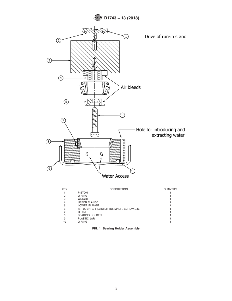
6.3 Bearing Holder, consists of a 1 kg 6 0.10 kg weight,
Subcommittee D02.G0.06 on Functional Tests - Contamination.
upper and lower plastic collars for the bearing cone (Parts A
Current edition approved April 1, 2018. Published May 2018. Originally
approved in 1960. Last previous edition approved in 2013 as D1743 – 13. DOI:
and B), a metal screw, and a plastic collar for the cup (Part C).
10.1520/D1743-13R18.
(See Fig. 1.)
“Research Technique for Determining Rust-Preventive Properties of Lubricat-
ing Greases in the Presence of Free Water,” L-41-957, undated, Coordinating
Research Council, Inc., 219 Perimeter Center Parkway, Atlanta, GA 30346. The sole source of supply of the apparatus known to the committee at this time
For referenced ASTM standards, visit the ASTM website, www.astm.org, or is The Timken Co., Canton, OH 44706.
contact ASTM Customer Service at service@astm.org. For Annual Book of ASTM If you are aware of alternative suppliers, please provide this information to
Standards volume information, refer to the standard’s Document Summary page on ASTM International Headquarters. Your comments will receive careful consider-
the ASTM website. ation at a meeting of the responsible technical committee, which you may attend.
Copyright © ASTM International, 100 Barr Harbor Drive, PO Box C700, West Conshohocken, PA 19428-2959. United States
D1743 − 13 (2018)
KEY DESCRIPTION QUANTITY
1PISTON 1
2 O RING 1
3 WEIGHT 1
4 UPPER FLANGE 1
5 LOWER FLANGE 1
1 1
6 ⁄4−20×1- ⁄4 FILLISTER HD. MACH. SCREW S.S. 1
7 O RING 1
8 BEARING HOLDER 1
9 PLASTIC JAR 1
10 O RING 1
FIG. 1 Bearing Holder Assembly
D1743 − 13 (2018)
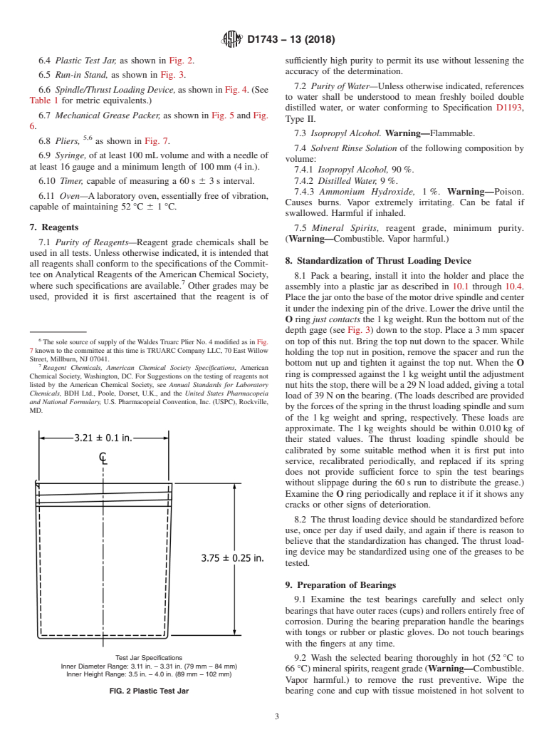
6.4 Plastic Test Jar, as shown in Fig. 2. sufficiently high purity to permit its use without lessening the
accuracy of the determination.
6.5 Run-in Stand, as shown in Fig. 3.
7.2 Purity of Water—Unless otherwise indicated, references
6.6 Spindle/Thrust Loading Device, as shown in Fig. 4. (See
to water shall be understood to mean freshly boiled double
Table 1 for metric equivalents.)
distilled water, or water conforming to Specification D1193,
6.7 Mechanical Grease Packer, as shown in Fig. 5 and Fig.
Type II.
6.
7.3 Isopropyl Alcohol. Warning—Flammable.
5,6
6.8 Pliers, as shown in Fig. 7.
7.4 Solvent Rinse Solution of the following composition by
6.9 Syringe, of at least 100 mLvolume and with a needle of
volume:
at least 16 gauge and a minimum length of 100 mm (4 in.).
7.4.1 Isopropyl Alcohol, 90 %.
7.4.2 Distilled Water,9%.
6.10 Timer, capable of measuring a 60 s 6 3 s interval.
7.4.3 Ammonium Hydroxide, 1%. Warning—Poison.
6.11 Oven—Alaboratory oven, essentially free of vibration,
Causes burns. Vapor extremely irritating. Can be fatal if
capable of maintaining 52 °C 6 1 °C.
swallowed. Harmful if inhaled.
7. Reagents
7.5 Mineral Spirits, reagent grade, minimum purity.
(Warning—Combustible. Vapor harmful.)
7.1 Purity of Reagents—Reagent grade chemicals shall be
used in all tests. Unless otherwise indicated, it is intended that
8. Standardization of Thrust Loading Device
all reagents shall conform to the specifications of the Commit-
tee onAnalytical Reagents of theAmerican Chemical Society,
8.1 Pack a bearing, install it into the holder and place the
where such specifications are available. Other grades may be
assembly into a plastic jar as described in 10.1 through 10.4.
used, provided it is first ascertained that the reagent is of
Placethejarontothebaseofthemotordrivespindleandcenter
it under the indexing pin of the drive. Lower the drive until the
O ring just contacts the 1 kg weight. Run the bottom nut of the
depth gage (see Fig. 3) down to the stop. Place a 3 mm spacer
The sole source of supply of the Waldes Truarc Plier No. 4 modified as in Fig. on top of this nut. Bring the top nut down to the spacer. While
7 known to the committee at this time is TRUARC Company LLC, 70 East Willow
holding the top nut in position, remove the spacer and run the
Street, Millburn, NJ 07041.
bottom nut up and tighten it against the top nut. When the O
Reagent Chemicals, American Chemical Society Specifications, American
ring is compressed against the 1 kg weight until the adjustment
Chemical Society, Washington, DC. For Suggestions on the testing of reagents not
listed by the American Chemical Society, see Annual Standards for Laboratory
nut hits the stop, there will be a 29 N load added, giving a total
Chemicals, BDH Ltd., Poole, Dorset, U.K., and the United States Pharmacopeia
load of 39 N on the bearing. (The loads described are provided
and National Formulary, U.S. Pharmacopeial Convention, Inc. (USPC), Rockville,
bytheforcesofthespringinthethrustloadingspindleandsum
MD.
of the 1 kg weight and spring, respectively. These loads are
approximate. The 1 kg weights should be within 0.010 kg of
their stated values. The thrust loading spindle should be
calibrated by some suitable method when it is first put into
service, recalibrated periodically, and replaced if its spring
does not provide sufficient force to spin the test bearings
without slippage during the 60 s run to distribute the grease.)
Examine the O ring periodically and replace it if it shows any
cracks or other signs of deterioration.
8.2 The thrust loading device should be standardized before
use, once per day if used daily, and again if there is reason to
believe that the standardization has changed. The thrust load-
ing device may be standardized using one of the greases to be
tested.
9. Preparation of Bearings
9.1 Examine the test bearings carefully and select only
bearingsthathaveouterraces(cups)androllersentirelyfreeof
corrosion. During the bearing preparation handle the bearings
with tongs or rubber or plastic gloves. Do not touch bearings
with the fingers at any time.
Test Jar Specifications
9.2 Wash the selected bearing thoroughly in hot (52 °C to
Inner Diameter Range: 3.11 in. – 3.31 in. (79 mm – 84 mm)
66 °C)mineralspirits,reagentgrade(Warning—Combustible.
Inner Height Range: 3.5 in. – 4.0 in. (89 mm – 102 mm)
Vapor harmful.) to remove the rust preventive. Wipe the
FIG. 2 Plastic Test Jar bearing cone and cup with tissue moistened in hot solvent to
D1743 − 13 (2018)
FIG. 3 Run-in Stand Drawing
FIG. 4 Spindle/Thrust Loading Device
D1743 − 13 (2018)
TABLE 1 Metric Equivalents for Figs. 3 and 4
10.2 Fill the reservoir with the grease sample, and use the
Inches Millimetres plunger to force grease through the bearing. Carefully remove
⁄32 0.79 the plunger from the reservoir to avoid sucking air into the
⁄8 3.18
bearing, and slide the packer unit over the edge of the bench.
⁄32 3.97
While holding the bearing assembly in the packer, invert the
⁄16 4.76
⁄32 7.14 unit to its original position on the bench.
⁄16 7.94
10.3 Using a small square-ended spatula, remove excess
⁄8 9.53
⁄16 11.11
grease from the bearing bore and the annulus between the
⁄2 12.70
grease packer and outer perimeter of the bearing cup. The
⁄32 15.08
21 bearing is removed from the packer by either use of the pliers
⁄32 16.67
⁄4 19.05 or by placing gloved index finger in the bore and lifting out.
1 25.40
While holding the bearing, use the spatula to remove excess
1 ⁄8 28.58
3 grease above the cage on both sides of the bearing. This
1 ⁄16 31.26
1 ⁄4 31.75
procedure is done to ensure that approximately the same
1 ⁄32 34.13
volume of grease is used each time.
1.495 37.97
1.500 38.10
10.4 Using Fig. 1 as a guide, hold the packed bearing
1 ⁄16 39.69
between gloved fingers with large inside diameter of cup
1 ⁄4 44.45
downwardandinsertthesmalldiameterplasticflangeontopof
1.785 45.34
1 ⁄16 49.21
thebore,andthelargerflangeintothebottomofthebore.Slide
1.946 49.43
the bearing assembly onto the 1 kg weight so that the large
2 ⁄32 56.36
1 diameter flange fits into the recess on the top of the weight.
2 ⁄4 57.15
2 ⁄32 59.53
Insert the bolt through the assembly and screw the bolt tightly
3 76.20
into the weight. Lower the plastic bearing holder (Part 8) over
the bearing (the large O ring faces upward). Press down the
holder so that the bearing fits squarely into the holder.
removeanyremainingresidue.Rinsethebearingasecondtime
NOTE 3—If bearing holders and plastic test jars are used interchange-
in fresh, hot mineral spirits, reagent grade.
ably for Test Method D5969 and D1743, thoroughly clean the test
apparatus to prevent contamination affecting the test results.
NOTE 1—The washing temperatures specified are considerably above
the flash point of the mineral spirits, reagent grade. Accordingly, the
10.5 Invert a plastic jar over the bearing assembly. Slide the
washing operation should be carried out in a well-ventilated hood where
two components over the edge of the bench, and with fingers
no flames or other ignition sources are present.
pressing the weight against the inner bottom of the jar, invert
9.3 Transfer the bearing from the mineral spirits, reagent
the entire assembly.
grade to the solvent rinse solution (Warning—Poison. Causes
10.6 Place the jar onto the base of the motor driven spindle
burns. Vapor extremely irritating. Can be fatal if swallowed.
and center under the indexing pin of the drive. Start the motor
Harmful if inhaled.) to remove the mineral spirits, reagent
and bring the drive into the center of the 1 kg weight and load
grade and any fingerprints that are present. Then rinse the
until the nut hits the depth stop. Run for 60 s, raise the drive,
bearing and slowly rotate in fresh hot (66 °C 6 5 °C) solvent
and allow the bearing to coast to a stop. Extreme care should
rinse solution.
be taken not to break the contact between the races and rollers
NOTE 2—Use fresh rinse solution to avoid the selective evaporation of at this point and in the following steps.
the components at the rinse temperature.
10.6.1 At no time during or after the 60 s run shall the
grease be redistributed or forced back into the bearing.
9.4 Remove the bearing from the solvent rinse solution and
place on filter paper to drain.After draining, dry the bearing in
10.7 Freshly boil the distilled water for 10 min 6 5 min to
an oven at 70 °C 6 5 °C for 15 min to 30 min.
remove carbon dioxide and cool to 25 °C 6 5 °C.
9.5 Permit the bearing to cool to room temperature and
10.8 Fill a clean syringe with 100 mL 6 5 mL of distilled
reexamine surfaces to assure that corrosion-free and free-
water from 10.7. With the run-in bearing in the jar, simultane-
turning specimens have been selected. (Care should be taken
ously start a timer and begin adding the water into the hole
not to spin the bearings after cleaning and drying.)
provided for this purpose in the bearing holder. Add the
100 mLof water within 20 s 6 3 s.When the timer shows 50 s
9.6 Wash and dry the bearing packer using the same
6 3 s start withdrawing the water. When the timer shows 60 s
technique as for the preparation of the bearings.
6 3 s, complete the withdrawal of 70 mL 6 5 mL of water.
10. Procedure
Leave the remaining 30 mL 6 5 mL of water in the jar. Make
sure that water does not touch the bearing after 70 mL 65mL
10.1 With the reservoir of grease packer resting on a clean
is withdrawn. It may be difficult to withdraw 70 mL 65mL
bench top, and while wearing gloves,
...
This document is not an ASTM standard and is intended only to provide the user of an ASTM standard an indication of what changes have been made to the previous version. Because
it may not be technically possible to adequately depict all changes accurately, ASTM recommends that users consult prior editions as appropriate. In all cases only the current version
of the standard as published by ASTM is to be considered the official document.
Designation: D1743 − 13 D1743 − 13 (Reapproved 2018)
Standard Test Method for
Determining Corrosion Preventive Properties of Lubricating
Greases
This standard is issued under the fixed designation D1743; the number immediately following the designation indicates the year of
original adoption or, in the case of revision, the year of last revision. A number in parentheses indicates the year of last reapproval. A
superscript epsilon (´) indicates an editorial change since the last revision or reapproval.
This standard has been approved for use by agencies of the U.S. Department of Defense.
1. Scope*Scope
1.1 This test method covers the determination of the corrosion preventive properties of greases using grease-lubricated tapered
roller bearings stored under wet conditions. This test method is based on CRC Technique L 41 that shows correlations between
laboratory results and service for grease lubricated aircraft wheel bearings.
1.2 Apparatus Dimensions—The values stated in SI units are to be regarded as standard. The values given in parentheses are
for information only.
1.3 All Other Values—The values stated in SI units are to be regarded as standard. No other units of measurement are included
in this standard.
1.4 This standard does not purport to address all of the safety concerns, if any, associated with its use. It is the responsibility
of the user of this standard to establish appropriate safety safety, health, and healthenvironmental practices and determine the
applicability of regulatory limitations prior to use.
1.5 This international standard was developed in accordance with internationally recognized principles on standardization
established in the Decision on Principles for the Development of International Standards, Guides and Recommendations issued
by the World Trade Organization Technical Barriers to Trade (TBT) Committee.
2. Referenced Documents
2.1 ASTM Standards:
D1193 Specification for Reagent Water
D5969 Test Method for Corrosion-Preventive Properties of Lubricating Greases in Presence of Dilute Synthetic Sea Water
Environments
3. Terminology
3.1 Definitions of Terms Specific to This Standard:
3.1.1 corrosion, n—the chemical or electrochemical reaction between a material, usually a metal, and its environment that
produces a deterioration of the material and its properties.
3.1.1.1 Discussion—
In this test method, corrosion is manifested by red rust or black stains on the bearing race. Stains, through which the underlying
metal surface is still visible, are not considered corrosion in Test Method D1743 and shall be ignored.
This test method is under the jurisdiction of ASTM Committee D02 on Petroleum Products, Liquid Fuels, and Lubricants and is the direct responsibility of Subcommittee
D02.G0.06 on Functional Tests - Contamination.
Current edition approved May 1, 2013April 1, 2018. Published May 2013May 2018. Originally approved in 1960. Last previous edition approved in 20102013 as
D1743 – 10.D1743 – 13. DOI: 10.1520/D1743-13.10.1520/D1743-13R18.
“Research Technique for Determining Rust-Preventive Properties of Lubricating Greases in the Presence of Free Water,” L-41-957, undated, Coordinating Research
Council, Inc., 219 Perimeter Center Parkway, Atlanta, GA 30346.
For referenced ASTM standards, visit the ASTM website, www.astm.org, or contact ASTM Customer Service at service@astm.org. For Annual Book of ASTM Standards
volume information, refer to the standard’s Document Summary page on the ASTM website.
*A Summary of Changes section appears at the end of this standard
Copyright © ASTM International, 100 Barr Harbor Drive, PO Box C700, West Conshohocken, PA 19428-2959. United States
D1743 − 13 (2018)
4. Summary of Test Method
4.1 New, cleaned, and lubricated bearings are run under a light thrust load for 6060 s 6 3 s 3 s to distribute the lubricant in a
pattern that might be found in service. The bearings are exposed to water, then stored for 4848 h 6 0.5 h 0.5 h at 5252 °C 6 1°C
(1251 °C (125 °F 6 2°F)2 °F) and 100 % relative humidity. After cleaning, the bearing cups are examined for evidence of
corrosion.
5. Significance and Use
5.1 This test method differentiates the relative corrosion-preventive capabilities of lubricating greases under the conditions of
the test.
6. Apparatus
4 ,5
6.1 Bearings—Timken bearing cone and roller assembly LM11949, and cup LM11910.
6.2 Motor, 17501750 r ⁄min 6 50-rpm50 r ⁄min speed, ⁄15 hp hp (min).
6.3 Bearing Holder, consists of a 11 kg 6 0.10 kg 0.10 kg weight, upper and lower plastic collars for the bearing cone (Parts
A and B), a metal screw, and a plastic collar for the cup (Part C). (See Fig. 1.)
6.4 Plastic Test Jar, as shown in Fig. 2.
6.5 Run-in Stand, as shown in Fig. 3.
6.6 Spindle/Thrust Loading Device, as shown in Fig. 4. (See Table 1 for metric equivalents.)
6.7 Mechanical Grease Packer, as shown in Fig. 5 and Fig. 6.
5,6
6.8 Pliers, as shown in Fig. 7.
6.9 Syringe, of at least 100-mL100 mL volume and with a needle of at least 16 gage 16 gauge and a minimum length of 100
mm (4 in.).100 mm (4 in.).
6.10 Timer, capable of measuring a 6060 s 6 3-s3 s interval.
6.11 Oven—A laboratory oven, essentially free of vibration, capable of maintaining 5252 °C 6 1°C.1 °C.
7. Reagents
7.1 Purity of Reagents—Reagent grade chemicals shall be used in all tests. Unless otherwise indicated, it is intended that all
reagents shall conform to the specifications of the Committee on Analytical Reagents of the American Chemical Society, where
such specifications are available. Other grades may be used, provided it is first ascertained that the reagent is of sufficiently high
purity to permit its use without lessening the accuracy of the determination.
7.2 Purity of Water—Unless otherwise indicated, references to water shall be understood to mean freshly boiled double distilled
water, or water conforming to Specification D1193, Type II.
7.3 Isopropyl Alcohol. Warning—Flammable.Warning—Flammable.
7.4 Solvent Rinse Solution of the following composition by volume:
7.4.1 Isopropyl Alcohol, 90 %.
7.4.2 Distilled Water, 9 %.
7.4.3 Ammonium Hydroxide, 1 %. Warning—Warning—Poison. Causes burns. Vapor extremely irritating. Can be fatal if
swallowed. Harmful if inhaled.
7.5 Mineral Spirits, reagent grade, minimum purity. (Warning—Warning—Combustible. Vapor harmful.)
8. Standardization of Thrust Loading Device
8.1 Pack a bearing, install it into the holder and place the assembly into a plastic jar as described in 10.1 through 10.4. Place
the jar onto the base of the motor drive spindle and center it under the indexing pin of the drive. Lower the drive until the O ring
just contacts the 1-kg1 kg weight. Run the bottom nut of the depth gage (see Fig. 3) down to the stop. Place a 3-mm3 mm spacer
on top of this nut. Bring the top nut down to the spacer. While holding the top nut in position, remove the spacer and run the bottom
The sole source of supply of the apparatus known to the committee at this time is The Timken Co., Canton, OH 44706.
If you are aware of alternative suppliers, please provide this information to ASTM International Headquarters. Your comments will receive careful consideration at a
meeting of the responsible technical committee, which you may attend.
The sole source of supply of the Waldes Truarc Plier No. 4 modified as in Fig. 7 known to the committee at this time is TRUARC Company LLC, 70 East Willow Street,
Millburn, NJ 07041.
Reagent Chemicals, American Chemical Society Specifications, American Chemical Society, Washington, DC. For Suggestions on the testing of reagents not listed by
the American Chemical Society, see Annual Standards for Laboratory Chemicals, BDH Ltd., Poole, Dorset, U.K., and the United States Pharmacopeia and National
Formulary, U.S. Pharmacopeial Convention, Inc. (USPC), Rockville, MD.
D1743 − 13 (2018)
KEY DESCRIPTION QUANTITY
1 PISTON 1
2 O RING 1
3 WEIGHT 1
4 UPPER FLANGE 1
5 LOWER FLANGE 1
1 1
6 ⁄4 − 20 × 1- ⁄4 FILLISTER HD. MACH. SCREW S.S. 1
7 O RING 1
8 BEARING HOLDER 1
9 PLASTIC JAR 1
10 O RING 1
FIG. 1 Bearing Holder Assembly
D1743 − 13 (2018)
Test Jar Specifications
Inner Diameter Range: 3.11–3.31 in. (79–84 mm)
Inner Diameter Range: 3.11 in. – 3.31 in. (79 mm – 84 mm)
Inner Height Range: 3.5–4.0 in. (89–102 mm)
Inner Height Range: 3.5 in. – 4.0 in. (89 mm – 102 mm)
FIG. 2 Plastic Test Jar
nut up and tighten it against the top nut. When the O ring is compressed against the 1-kg1 kg weight until the adjustment nut hits
the stop, there will be a 29-N29 N load added, giving a total load of 39 N 39 N on the bearing. (The loads described are provided
by the forces of the spring in the thrust loading spindle and sum of the 1-kg1 kg weight and spring, respectively. These loads are
approximate. The 1-kg1 kg weights should be within 0.010 kg 0.010 kg of their stated values. The thrust loading spindle should
be calibrated by some suitable method when it is first put into service, recalibrated periodically, and replaced if its spring does not
provide sufficient force to spin the test bearings without slippage during the 60 s 60 s run to distribute the grease.) Examine the
O ring periodically and replace it if it shows any cracks or other signs of deterioration.
8.2 The thrust loading device should be standardized before use, once per day if used daily, and again if there is reason to believe
that the standardization has changed. The thrust loading device may be standardized using one of the greases to be tested.
9. Preparation of Bearings
9.1 Examine the test bearings carefully and select only bearings that have outer races (cups) and rollers entirely free of
corrosion. During the bearing preparation handle the bearings with tongs or rubber or plastic gloves. Do not touch bearings with
the fingers at any time.
9.2 Wash the selected bearing thoroughly in hot (52(52 °C to 66°C)66 °C) mineral spirits, reagent grade (Warning—Warning—
Combustible. Vapor harmful.) to remove the rust preventive. Wipe the bearing cone and cup with tissue moistened in hot solvent
to remove any remaining residue. Rinse the bearing a second time in fresh, hot mineral spirits, reagent grade.
NOTE 1—The washing temperatures specified are considerably above the flash point of the mineral spirits, reagent grade. Accordingly, the washing
operation should be carried out in a well-ventilated hood where no flames or other ignition sources are present.
9.3 Transfer the bearing from the mineral spirits, reagent grade to the solvent rinse solution (Warning—Warning— Poison.
Causes burns. Vapor extremely irritating. Can be fatal if swallowed. Harmful if inhaled.) to remove the mineral spirits, reagent
grade and any fingerprints that are present. Then rinse the bearing and slowly rotate in fresh hot (66(66 °C 6 5°C)5 °C) solvent
rinse solution.
NOTE 2—Use fresh rinse solution to avoid the selective evaporation of the components at the rinse temperature.
9.4 Remove the bearing from the solvent rinse solution and place on filter paper to drain. After draining, dry the bearing in an
oven at 7070 °C 6 5°C5 °C for 1515 min to 30 min.30 min.
9.5 Permit the bearing to cool to room temperature and reexamine surfaces to assure that corrosion-free and free-turning
specimens have been selected. (Care should be taken not to spin the bearings after cleaning and drying.)
D1743 − 13 (2018)
FIG. 3 Run-in Stand Drawing
FIG. 4 Spindle/Thrust Loading Device
D1743 − 13 (2018)
TABLE 1 Metric Equivalents for Figs. 3 and 4
Inches Millimetres
⁄32 0.79
⁄8 3.18
⁄32 3.97
⁄16 4.76
⁄32 7.14
⁄16 7.94
⁄8 9.53
⁄16 11.11
⁄2 12.70
⁄32 15.08
⁄32 16.67
⁄4 19.05
1 25.40
1 ⁄8 28.58
1 ⁄16 31.26
1 ⁄4 31.75
1 ⁄32 34.13
1.495 37.97
1.500 38.10
1 ⁄16 39.69
1 ⁄4 44.45
1.785 45.34
1 ⁄16 49.21
1.946 49.43
2 ⁄32 56.36
2 ⁄4 57.15
2 ⁄32 59.53
3 76.20
9.6 Wash and dry the bearing packer using the same technique as for the preparation of the bearings.
10. Procedure
10.1 With the reservoir of grease packer resting on a clean bench top, and while wearing gloves, place bearing cup with small
diameter face down into the recess of the packer. Place the bearing cone over the cup, and while holding the bearing assembly
against the packer, lift and invert the whole unit and return it to the bench.
10.2 Fill the reservoir with the grease sample, and use the plunger to force grease through the bearing. Carefully remove the
plunger from the reservoir to avoid sucking air into the bearing, and slide the packer unit over the edge of the bench. While holding
the bearing assembly in the packer, invert the unit to its original position on the bench.
10.3 Using a small square-ended spatula, remove excess grease from the bearing bore and the annulus between the grease
packer and outer perimeter of the bearing cup. The bearing is removed from the packer by either use of the pliers or by placing
gloved index finger in the bore and lifting out. While holding the bearing, use the spatula to remove excess grease above the cage
on both sides of the bearing. This procedure is done to ensure that approximately the same volume of grease is used each time.
10.4 Using Fig. 1 as a guide, hold the packed bearing between gloved fingers with large inside diameter of cup downward and
insert the small diameter plastic flange on top of the bore, and the larger flange into the bottom of the bore. Slide the bearing
assembly onto the 1-kg1 kg weight so that the large diameter flange fits into the recess on the top of the weight. Insert the bolt
through the assembly and screw the bolt tightly into the weight. Lower the plastic bearing holder (Part 8) over the bearing (the
large O ring faces upward). Press down the holder so that the bearing fits squarely into the holder.
NOTE 3—If bearing holders and plastic test jars are used interchangeably for Test Method D5969 and D1743D1743,, thoroughly clean the test apparatus
to prevent contamination affecting the test results.
10.5 Invert a plastic jar over the bearing assembly. Slide the two components over the edge of the bench, and with fingers
pressing the weight against the inner bottom of the jar, invert the entire assembly.
10.6 Place the jar onto the base of the motor driven spindle and center under the indexing pin of the drive. Start the motor and
...
Questions, Comments and Discussion
Ask us and Technical Secretary will try to provide an answer. You can facilitate discussion about the standard in here.